Siemens SITRANS F M MAG 1100 Operating Instructions Manual
Electromagnetic flowmeter sensor
Hide thumbs
Also See for SITRANS F M MAG 1100:
- Handbook (92 pages) ,
- Operating instructions manual (75 pages) ,
- Quick start manual (16 pages)
Table of Contents
Advertisement
Quick Links
Electromagnetic Flowmeters
SITRANS F M MAG 1100 sensor
Operating Instructions
Electromagnetic flow sensor designed for use with
transmitter types SITRANS F M MAG 5000 / 6000 and
MAG 6000 I
01/2018
A5E03433301-AC
Introduction
Safety notes
Description
Installing/Mounting
Connecting
Service and maintenance
Troubleshooting
Technical data
Appendix
1
2
3
4
5
6
7
8
A
Advertisement
Table of Contents

Related Manuals for Siemens SITRANS F M MAG 1100


Summary of Contents for Siemens SITRANS F M MAG 1100
- Page 1 Introduction Safety notes Description Installing/Mounting Electromagnetic Flowmeters SITRANS F M MAG 1100 sensor Connecting Service and maintenance Operating Instructions Troubleshooting Technical data Appendix Electromagnetic flow sensor designed for use with transmitter types SITRANS F M MAG 5000 / 6000 and...
- Page 2 Note the following: WARNING Siemens products may only be used for the applications described in the catalog and in the relevant technical documentation. If products and components from other manufacturers are used, these must be recommended or approved by Siemens. Proper transport, storage, installation, assembly, commissioning, operation and maintenance are required to ensure that the products operate safely and without any problems.
-
Page 3: Table Of Contents
Mounting with a welding type adapter..................29 4.6.2 Mounting with a clamp type adapter..................29 4.6.3 Mounting with a threaded type adapter..................30 Torques values........................30 Potential equalization......................31 Connecting..............................33 General safety requirements....................33 Remote installation.........................35 Installation check........................38 Potting............................39 SITRANS F M MAG 1100 sensor Operating Instructions, 01/2018, A5E03433301-AC... - Page 4 Pressure / temperature range....................54 Process fluid conductivity.......................55 8.10 Dimensions and weight......................56 8.11 Accessories for MAG 1100 F....................59 8.12 Certificates and approvals......................62 Appendix..............................65 Factory settings........................65 Coil resistance........................66 Ordering of spare parts......................67 Index................................69 SITRANS F M MAG 1100 sensor Operating Instructions, 01/2018, A5E03433301-AC...
-
Page 5: Introduction
It is the responsibility of the customer that the instructions and directions provided in the operating instructions are read, understood, and followed by the relevant personnel before installing the device. Items supplied ● SITRANS F M MAG 1100 ● Calibration report ● SITRANS F M literature CD ● Quick Start guide... -
Page 6: History
Figure 1-2 MAG 1100 Ex identification nameplate example History The contents of these instructions are regularly reviewed and corrections are included in subsequent editions. We welcome all suggestions for improvement. SITRANS F M MAG 1100 sensor Operating Instructions, 01/2018, A5E03433301-AC... -
Page 7: Further Information
Product information on the Internet The Operating Instructions are available on the documentation disk shipped with the device, and on the Internet on the Siemens homepage, where further information on the range of SITRANS F flowmeters may also be found: Local contact person (http://www.automation.siemens.com/partner) - Page 8 Introduction 1.4 Further Information SITRANS F M MAG 1100 sensor Operating Instructions, 01/2018, A5E03433301-AC...
-
Page 9: Safety Notes
Material compatibility Siemens Flow Instruments can provide assistance with the selection of wetted sensor parts. However, the full responsibility for the selection rests with the customer and Siemens Flow Instruments can take no responsibility for any failure due to material incompatibility. - Page 10 PED directive Pressure Equipment Directive" (PED) is mandatory for all pressure equipment sold within the EU and EFTA. Siemens Flow Instruments products comply with PED as stated in the following table. Table 2-1 MAG 1100 and MAG 1100 HT PED compliance...
-
Page 11: Installation In Hazardous Area
With intrinsically safe circuits, use only certified meters appropriate for the transmitter. If a non-conforming supply unit is used, the "fail-safe" type of protection will no longer be effective and the approval certification will be invalid. SITRANS F M MAG 1100 sensor Operating Instructions, 01/2018, A5E03433301-AC... - Page 12 Connect the devices that are operated in hazardous areas as per the stipulations applicable in the country of operation, e.g. for Ex "d" and "nA", permanent cables must be laid. SITRANS F M MAG 1100 sensor Operating Instructions, 01/2018, A5E03433301-AC...
-
Page 13: Certificates
Safety notes 2.3 Certificates Certificates You can find certificates on the Internet at online support portal (http://www.siemens.com/ processinstrumentation/certificates) or on an included DVD. See also Technical data (Page 49) SITRANS F M MAG 1100 sensor Operating Instructions, 01/2018, A5E03433301-AC... - Page 14 Safety notes 2.3 Certificates SITRANS F M MAG 1100 sensor Operating Instructions, 01/2018, A5E03433301-AC...
-
Page 15: Description
The SITRANS F M flowmeter system includes: ● Transmitter (types: SITRANS F M MAG 5000/6000 or MAG 6000 I) ● Sensor (types: SITRANS F M MAG 1100/1100 F, MAG 3100/3100 P or MAG 5100 W) ● Communication module (optional) (types: HART, PROFIBUS PA/DP, MODBUS RTU RS 485, Foundation Fieldbus H1, Devicenet) ●... -
Page 16: Design
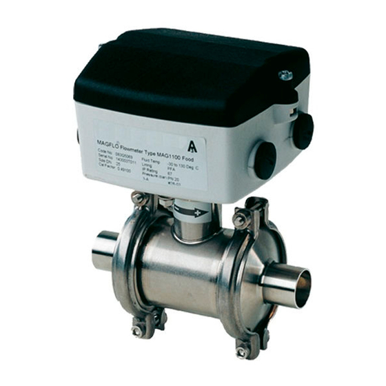
Description 3.3 Design Design The SITRANS F M MAG 1100 is an electromagnetic flow sensor in a compact wafer design designed for flow applications in the process industry. MAG 1100 MAG 5000 MAG 6000I Sensor housing and flanges are designed in carbon steel (ASTM A 105) and terminal box in fibre glass reinforced polyamide or optionally in stainless steel (AISI 316). -
Page 17: Theory Of Operation
The analog to digital conversion takes place in an ultra low noise ASIC with 23 bit signal resolution. This has eliminated the need for range switching. The dynamic range of the transmitter is therefore unsurpassed with a turn down ratio of minimum 3000:1. SITRANS F M MAG 1100 sensor Operating Instructions, 01/2018, A5E03433301-AC... - Page 18 Description 3.4 Theory of operation SITRANS F M MAG 1100 sensor Operating Instructions, 01/2018, A5E03433301-AC...
-
Page 19: Installing/Mounting
Note Install the sensor in well-supported pipelines in order to support the weight of the flowmeter. SITRANS F M MAG 1100 sensor Operating Instructions, 01/2018, A5E03433301-AC... -
Page 20: Determining A Location
To achieve accurate flow measurement it is essential to have straight lengths of inlet and outlet pipes and a certain distance to pumps and valves. It is also important to centre the flowmeter in relation to pipe flanges and gaskets. SITRANS F M MAG 1100 sensor Operating Instructions, 01/2018, A5E03433301-AC... -
Page 21: Installation In Partially Filled Pipes
Installation in large pipes The flowmeter can be installed between two reducers (for example DIN 28545). At α ≤ 8° the following pressure drop curves apply. The curves are applicable to water. SITRANS F M MAG 1100 sensor Operating Instructions, 01/2018, A5E03433301-AC... - Page 22 Example: A flow of 3 m/s (v) in a sensor with a diameter reduction from DN 100 to DN 80 (d = 0.8) gives a pressure drop of 2.9 mbar. SITRANS F M MAG 1100 sensor Operating Instructions, 01/2018, A5E03433301-AC...
-
Page 23: Orienting The Sensor
Installing/Mounting 4.4 Orienting the sensor Orienting the sensor The sensor operates in all orientations, but Siemens has the following recommendations: ● Vertical installation with an upwards flow Figure 4-4 Vertical orientation, upwards flow NOTICE Abrasive liquids / liquids containing solid particles... -
Page 24: Mounting Mag 1100/1100 Ht
● Use proper gaskets according to liner type Remove liner protectors before installing the flow meter 1. Existing pipe 2. Flange 3. Sensor 4. Gaskets 5. Sensor length incl. gaskets SITRANS F M MAG 1100 sensor Operating Instructions, 01/2018, A5E03433301-AC... - Page 25 These should be tightened gently, making sure that each gasket fits exactly into its recess at either end of the sensor The remaining flange bolts can now be inserted and tightened using about 25% of the actual tightening torque, see table below. SITRANS F M MAG 1100 sensor Operating Instructions, 01/2018, A5E03433301-AC...
- Page 26 The bolts must now be cross-tightened in the sequence shown, using up to 100% torque. 10 Nm - 1 kpm NOTICE Do not use sharp objects to remove the blanks as this can damage the liner! SITRANS F M MAG 1100 sensor Operating Instructions, 01/2018, A5E03433301-AC...
-
Page 27: Mounting Mag 1100 F
Avoid strong vibrations. Figure 4-7 Avoid vibrations CAUTION In applications with strong vibrations, Siemens recommends remote mounting of the transmitter! Mounting MAG 1100 F The MAG 1100 F sensor has an integrated clamp connection and is designed for installation between two adapters, which are supplied separately. The adapters are available for a variety of standards according to: ISO, DIN, SMS, BS and DS, for direct welding into dairy pipes or with clamp- or threaded fittings. - Page 28 Turning the sensor around the adapter centre line after the clamp rings have been fastened will damage the liner. The sensor may therefore only be turned when the clamp rings have either been removed or completely loosened. SITRANS F M MAG 1100 sensor Operating Instructions, 01/2018, A5E03433301-AC...
-
Page 29: Mounting With A Welding Type Adapter
2. Assemble the sensor and adapters together with the gaskets. 3. Place the clamp rings around the clamp connections between the adapters and pipeline. 4. Close and tighten the clamp rings. SITRANS F M MAG 1100 sensor Operating Instructions, 01/2018, A5E03433301-AC... -
Page 30: Mounting With A Threaded Type Adapter
Torque values are calculated on the basis of use of gaskets. mm/inch 10 / 15 / 25 / 1 40 / 1 50 / 2 65 / 2 80 / 3 100 / 4 SITRANS F M MAG 1100 sensor Operating Instructions, 01/2018, A5E03433301-AC... -
Page 31: Potential Equalization
For sizes DN 2-10 with Hastelloy or stainless steel adaptors potential equalization is done ensured through adaptors Cathodic protection Special attention must be paid to systems with cathodic protection WARNING Use in hazardous area! Cathodic pipe protection is not allowed in hazardous areas SITRANS F M MAG 1100 sensor Operating Instructions, 01/2018, A5E03433301-AC... - Page 32 If the above is not acceptable, remote mounted sensors can alternatively be connected as follows: ● Connect coil current cable shield at sensor end via a 1.5 µF condensator ● Make sure that electrode cable shield is not connected at both ends SITRANS F M MAG 1100 sensor Operating Instructions, 01/2018, A5E03433301-AC...
-
Page 33: Connecting
It must be marked as the disconnecting device for the equipment. Note Hazardous area applications Special requirements apply to the location and interconnection of sensor and transmitter. See Installation in hazardous area (Page 11). SITRANS F M MAG 1100 sensor Operating Instructions, 01/2018, A5E03433301-AC... - Page 34 If long cables are used in electrically noisy environments, it is recommended to use screened cables. Electrode cables Dotted connections are only to be made when using special electrode cables. WARNING National requirements Observe country-specific installation directives for field wiring. SITRANS F M MAG 1100 sensor Operating Instructions, 01/2018, A5E03433301-AC...
-
Page 35: Remote Installation
For field wiring installation: Ensure that the national requirements of the country in which the flowmeters are installed is met. Remote installation Note Remote installation only The following applies to remote installation of MAG 5000 / 6000 or MAG 6000 I. SITRANS F M MAG 1100 sensor Operating Instructions, 01/2018, A5E03433301-AC... - Page 36 ® see relevant transmitter operating instructions. 4. Fit the ½" NPT or M20 cable glands for supply and output cables. SITRANS F M MAG 1100 sensor Operating Instructions, 01/2018, A5E03433301-AC...
- Page 37 Brown Black Blue Coil cable Blue Brown Shield Note: Special cable with individual wire shields (shown as dotted lines) are only required when using empty pipe function or long cables. SITRANS F M MAG 1100 sensor Operating Instructions, 01/2018, A5E03433301-AC...
-
Page 38: Installation Check
Before commissioning it must be checked that: ● The device has been installed and connected in accordance with the guidelines provided previous in this chapter and in Installing/Mounting (Page 19). SITRANS F M MAG 1100 sensor Operating Instructions, 01/2018, A5E03433301-AC... -
Page 39: Potting
● Let cure for approximately 24 hours at approximately 25°C (77°F). Curing time increases by 100% per -10°C (-18°F). Horizontal orientation Vertical orientation Note Gel can be penetrated with test instruments or be removed in case of cable replacement. SITRANS F M MAG 1100 sensor Operating Instructions, 01/2018, A5E03433301-AC... - Page 40 Connecting 5.4 Potting SITRANS F M MAG 1100 sensor Operating Instructions, 01/2018, A5E03433301-AC...
-
Page 41: Service And Maintenance
Repair and service must be carried out by Siemens authorized personnel only. Note Siemens defines flow sensors as non-repairable products. Recalibration Siemens A/S Flow Instruments offers to recalibrate the sensor. The following calibration is offered: ● Standard matched pair calibration ● Customer-specified calibration up to 10 points ●... -
Page 42: Technical Support
● Information about field service, repairs, spare parts and lots more under Services. Additional Support If you have additional questions about the device, please contact your local Siemens representative and offices at: Local contact person (http://www.automation.siemens.com/partner) -
Page 43: Disposal
Contact your local Siemens contact (http://www.automation.siemens.com/partner) for futher information Alternatively Siemens Flow Instruments will accept back and dispose of the old instrument at no cost. Follow the return procedures of Siemens Flow Instruments described in chapter: Return procedures (Page 42) - Page 44 Service and maintenance 6.6 Disposal SITRANS F M MAG 1100 sensor Operating Instructions, 01/2018, A5E03433301-AC...
-
Page 45: Troubleshooting
To check the SITRANS F M sensors the following test instruments will be required: ● Digital Meter/Multimeter ● Megger ● (Moving Coil Meter) Sensor check Remove the transmitter from the sensor or remote position before making the following checks. SITRANS F M MAG 1100 sensor Operating Instructions, 01/2018, A5E03433301-AC... - Page 46 If the resistance is high and the pipe is completely full of fluid check the following: 1. Fluid is electrically conductive. 2. Electrodes are not coated with grease or any deposit. 3. Electrode circuit is not open. SITRANS F M MAG 1100 sensor Operating Instructions, 01/2018, A5E03433301-AC...
-
Page 47: Fluctuating Process Values
– Connect the electrode cable (82, 83, 0 and shield) according to the instructions in Connecting (Page 33) Note Vibrating environments It is recommended to use special low noise cables for sensor sizes DN 2 and DN 3 installed in vibrating environments. SITRANS F M MAG 1100 sensor Operating Instructions, 01/2018, A5E03433301-AC... - Page 48 Troubleshooting 7.3 Fluctuating process values SITRANS F M MAG 1100 sensor Operating Instructions, 01/2018, A5E03433301-AC...
-
Page 49: Technical Data
- DN 10 to 100 (3/8" to 4") 4825-3 Threaded type DIN 11851 - DN 10 to 100 (3/8" to 4") SMS 1145 - DN 25 to 65 (1" to 2½") SITRANS F M MAG 1100 sensor Operating Instructions, 01/2018, A5E03433301-AC... -
Page 50: Rated Operating Conditions
DN 80 and 100: Max ΔT ≤ 60 °C/min (3" and 4": Max ΔT ≤ 108 °F/min) Max. ±100 °C (210 °F) Max. ± 100 °C (212 °F) momentarily momentarily SITRANS F M MAG 1100 sensor Operating Instructions, 01/2018, A5E03433301-AC... - Page 51 IP67 to EN 60529 (NEMA 4X), 1 IP67 to EN 60529 (NEMA 4X), 1 IP67 to EN 60529 (NEMA 4X), 1 O for 30 min 2004/108/EC O for 30 min 2004/108/EC mH2O for 30 min 2004/108/EC SITRANS F M MAG 1100 sensor Operating Instructions, 01/2018, A5E03433301-AC...
-
Page 52: Design
Aluminum oxide Al Zirconium oxide (ZrO ) (ceramic) Aluminum oxide Al DN 6 to 100 (¼" to 4"): Aluminum oxide Al Reinforced PFA (not for Ex) Reinforced PFA (not for Ex) SITRANS F M MAG 1100 sensor Operating Instructions, 01/2018, A5E03433301-AC... -
Page 53: Electrodes
MAG 6000 I: 2 x M25 (for supply/output) (for supply/output) – MAG 6000 I Ex de: 2 x – MAG 6000 I Ex de: 2 x M25 (for supply/output) M25 (for supply/output) SITRANS F M MAG 1100 sensor Operating Instructions, 01/2018, A5E03433301-AC... -
Page 54: Pressure / Temperature Range
Imperial measures (pressure in psi) - Sizes 1", 1½" and >12" Flange specifi‐ Flange rating Temperature (°F) cations EN 1092-1 PN 10 PN 16 PN 40 ANSI B16.5 150 lb AWWA C-207 Class D 150l SITRANS F M MAG 1100 sensor Operating Instructions, 01/2018, A5E03433301-AC... -
Page 55: Process Fluid Conductivity
Liquids with an electrical conductivity ≥ 5 μS/cm. Remote installation Standard cable [µS/cm] Conductivity of medium [ft] Cabel length Special cable [µS/cm] Conductivity of medium 150 300 600 1200 1500 [ft] Cable length SITRANS F M MAG 1100 sensor Operating Instructions, 01/2018, A5E03433301-AC... -
Page 56: Dimensions And Weight
1½ 6.34 12.40 7.33 0.08 6.34 12.40 7.33 0.12 ¼ 6.34 12.40 7.33 6.34 12.40 7.33 0.39 ½ 6.34 12.40 7.33 0.59 6.66 12.72 7.92 0.98 SITRANS F M MAG 1100 sensor Operating Instructions, 01/2018, A5E03433301-AC... - Page 57 200 / - 7.9/ - 10.8 12.8 250/ - 9.8/ - 15.0 When earthing flanges are used, the thickness of the earthing flange must be added to the built-in length SITRANS F M MAG 1100 sensor Operating Instructions, 01/2018, A5E03433301-AC...
- Page 58 5.75 ½ 3.90 5.75 4.45 6.34 1½ 4.96 6.93 6.06 7.32 2½ 6.50 8.78 7.87 10.16 8.86 11.34 The total built-in length "L" is independent of the adapter type selected. SITRANS F M MAG 1100 sensor Operating Instructions, 01/2018, A5E03433301-AC...
-
Page 59: Accessories For Mag 1100 F
38.0 41.0 48.6 51.6 47.5 50.8 50.0 53.0 63.5 60.3 64.1 60.2 63.5 66.0 70.0 76.1 72.9 76.7 72.9 76.2 81.0 85.0 101.6 97.6 102.5 97.38 101.6 114.3 110.3 115.6 SITRANS F M MAG 1100 sensor Operating Instructions, 01/2018, A5E03433301-AC... - Page 60 119.9 101.6 97.6 119.0 97.6 119.0 Table 8-19 Threaded type DIN 11851 Adapter Sensor Threaded type DIN 11851 10.0 28.0 16.0 34.0 20.0 44.0 26.0 52.0 32.0 58.0 38.0 65.0 SITRANS F M MAG 1100 sensor Operating Instructions, 01/2018, A5E03433301-AC...
- Page 61 37.0 35.6 51.0 35.6 51.0 48.6 64.0 48.6 64.0 63.5 60.3 78.0 60.3 78.0 76.1 72.9 91.0 72.9 91.0 101.6 97.6 126.0 101.6 97.6 118.0 Not suitable for 3A approval SITRANS F M MAG 1100 sensor Operating Instructions, 01/2018, A5E03433301-AC...
-
Page 62: Certificates And Approvals
- Zone 1 Ex d e ia IIC T6 - Zone 1 Ex e ia IIC T6 ATEX MAG 6000 I Ex - Zone 1 Ex e ia IIC T6 - Zone 21 Ex tD A21 IP67 SITRANS F M MAG 1100 sensor Operating Instructions, 01/2018, A5E03433301-AC... - Page 63 ● 3A (remote version with (PFA) Polyamide terminal box) ● EHEDG (remote version with Polyamide terminal box, DN 25 to 100 (1" to 4") ● Hygienic EC 1935:2004 European food contact material SITRANS F M MAG 1100 sensor Operating Instructions, 01/2018, A5E03433301-AC...
- Page 64 Technical data 8.12 Certificates and approvals SITRANS F M MAG 1100 sensor Operating Instructions, 01/2018, A5E03433301-AC...
-
Page 65: Appendix
US GPM US G US G 2½ 13.1 525.9 US GPM US G US G 19.9 796.7 US GPM US G US MG 31.1 1244.8 US GPM US G US MG SITRANS F M MAG 1100 sensor Operating Instructions, 01/2018, A5E03433301-AC... -
Page 66: Coil Resistance
0.000433 11331 2½ 0.000730 19149 0.00111 29007 0.00173 45325 Coil resistance Table A-5 Coil resistance [Ω] MAG 1100, MAG 1100F Inch Resistance Tolerance 1/12 +/− 5 +/− 5 +/− 17 SITRANS F M MAG 1100 sensor Operating Instructions, 01/2018, A5E03433301-AC... -
Page 67: Ordering Of Spare Parts
● The resistance changes proportionally 0.4% / °C Ordering of spare parts Ensure that your ordering data is not outdated. The latest ordering data is always available on the Internet: Catalog process instrumentation (http://www.siemens.com/ processinstrumentation/catalogs) SITRANS F M MAG 1100 sensor Operating Instructions, 01/2018, A5E03433301-AC... - Page 68 Appendix A.3 Ordering of spare parts SITRANS F M MAG 1100 sensor Operating Instructions, 01/2018, A5E03433301-AC...
-
Page 69: Index
Material, 16 Internet Electrode resistance check, 46 Contact person, 7, 42 Electrodes, 53 Flow documentation, 7 Empty pipe detection, 21 Support, 42 Intrinsically safe data, 11 Introduction, 5 Items supplied, 5 SITRANS F M MAG 1100 sensor Operating Instructions, 01/2018, A5E03433301-AC... - Page 70 Recalibration, 41 Repair, 41 Return procedures, 42 Safety, 9 Instrument safety standards, 9 Sensor installation, 19 Safety instructions Electrical connection, 33 Sensor check, 45 Sensor orientation, 23 Service, 41, 42 SITRANS F M MAG 1100 sensor Operating Instructions, 01/2018, A5E03433301-AC...
Need help?
Do you have a question about the SITRANS F M MAG 1100 and is the answer not in the manual?
Questions and answers