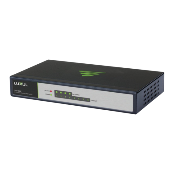
Luxul XFS-1084P Quick Install Manual
8-port
Hide thumbs
Also See for XFS-1084P:
- Quick install manual (11 pages) ,
- Quick install manual (11 pages) ,
- Quick install manual (2 pages)
Summary of Contents for Luxul XFS-1084P
-
Page 1: Quick Install Guide
QUICK INSTALL GUIDE 8-Port PoE Switch XFS-1084P Includes: One:„XFS-1084P„8-Port„PoE„Switch „ „ One:„Power„Adapter„and„Cord „ „... -
Page 2: Installation And Setup
INSTALLATION AND SETUP Physical Installation Place„the„XFS-1084P„horizontally„on„a„solid,„level„surface„in„a„stable/safe„place„ to„avoid„any„possible„damage.„Avoid„placement„in„direct„sunlight,„do„not„place„ heavy„articles„on„the„switch,„and„allow„for„proper„ventilation. XFS-1084P Front Panel and Side View Showing Ventilation... -
Page 3: Connecting Power
Connecting Power Use„any„RJ-45„to„connect„the„XFS-1084P„to„an„Ethernet-enabled„device,„„ including„servers,„routers„or„other„switches.„No„crossover„cable„is„necessary.„ Connect„the„power„adapter„plug„to„the„switch„power„connector,„then„ connect„the„included„AC„power„adapter„to„a„power„outlet. CAUTION: Use only the included AC power adapter, rated for 48VDC @ 1.25A. Using a different AC adapter could damage the XFS-1084P. XFS-1084P Rear Panel View... -
Page 4: Connecting Ethernet Devices
Connecting Ethernet Devices Connecting Devices Use„standard„Ethernet„CAT5,„CAT5e„or„CAT6„cable„to„connect„the„XFS- 1084P„to„a„device„as„described„below.„The„XFS-1084P„will„automatically„ adjust„to„the„speed„and„duplex„of„the„connected„device. The„PoE„function„is„autosensing.„As„long„as„the„powered„device„is„802.3af„ compliant,„the„switch„will„provide„power.„The„XFS-1084P„PoE„power„ budget„is„57W„total„and„a„maximum„of„15.4W„per„port. NOTE: The switch is not capable of powering legacy PoE devices or 802.3at devices that require more than 15.4 watts. 1.25A Connecting the XFS-1084P to a Device When„a„device„is„properly„connected,„the„Link/Activity„LEDs„for„each„„ port„lights„up„green.„Please„refer„to„the„LED„Indicators„section„for„defini- tions„and„troubleshooting. -
Page 5: Connecting To A Router Or Other Switch
Connecting to a Router or Other Switch For„best„performance,„and„to„maximize„available„ports,„Luxul„recommends„ connecting„LAN„devices„to„the„XFS-1084P,„then„connecting„the„switch„to„a„ router„LAN„port„or„another„switch„as„shown„in„the„illustration. Connecting the XFS-1084P to a Router and Devices When„a„device„is„properly„connected,„the„Link/Activity„LEDs„for„each„port„lights„ up„green.„Please„refer„to„the„following„section„on„LED„Indicators„for„definitions„ and„troubleshooting. NOTE: Ports 1-4 are PoE ports and should not be used for the uplink connection. -
Page 6: Rear Panel Layout
Hardware Operation Front Panel The„front„panel„of„the„XFS-1084P„includes„eight„Link/Activity„LEDs,„one„power„ LED,„four„PoE„Status„LEDs„and„one„PoE„Max„LED.„Refer„to„the„detailed„descrip- tion„of„these„indicators„in„the„following„section„on„LED„Indicators. XFS-1084P Front Panel View Rear Panel Layout The„Rear„Panel„of„the„XFS-1084P„includes„eight„10/100Mbps„RJ-45„Ethernet„ports„ and„one„DC„power„port„used„for„DC„power„input. XFS-1084P Rear Panel View LED Indicators The„LED„indicators„on„the„XFS-1084P„include„eight„Link/Activity„LEDs,„„ one„power„LED,„four„PoE„Status„LEDs„and„one„PoE„Max„LED.„These„„ LED„indicators„show„the„operating„status„of„the„XFS-1084P„and„„ each„switch„connection. - Page 7 The„following„chart„shows„the„LED„indicators„of„the„XFS-1084P„along„with„ an„explanation„of„the„indicator’ s „properties: Color Status Description Power Green The„XFS-1084P„is„powered. Check„the„DC„power„supply„to„ensure„ proper„connection„to„the„outlet„and„„ the„XFS-1084P. PoE„Max Red Maximum„output„wattage„reached. Flashing Maximum„output„wattage„exceeded. Maximum„output„wattage„not„reached. PoE„ Green Delivering„PoE„power„to„connected„device. Status Green Flashing Can„indicate„an„Ethernet„cable„short„or„the„ connected„device„is„attempting„to„draw„ more„than„15.4W. No„PoE„power„being„delivered. LINK/ Green The„XFS-1084P„is„connected. Green Flashing The„XFS-1084P„is„transmitting/receiving„ data„packets. The„port„is„not„connected„to„a„device.
-
Page 8: Legal And Regulatory Information
LEGAL AND REGULATORY INFORMATION No„part„of„this„publication,„or„any„other„publication„may„be„modified„or„ adapted„in„any„way,„for„any„purposes„without„permission„in„writing„from„ Luxul.„The„material„in„this„manual„is„subject„to„change„without„notice.„Luxul„ reserves„the„right„to„make„changes„to„any„product„to„improve„reliability,„ function,„or„design.„No„license„is„granted,„either„expressly„or„by„implication„or„ otherwise„under„any„Luxul„intellectual„property„rights.„An„implied„license„only„ exists„for„equipment,„circuits„and„subsystems„contained„in„this„or„any„Luxul„ product.„ FCC Compliance This„device„complies„with„Part„15„of„the„FCC„Rules.„Operation„is„subject„to„ the„following„two„conditions:„(1)„this„device„may„not„cause„harmful„inter- ference,„and„(2)„this„device„must„accept„any„interference„received,„including„ interference„that„may„cause„undesired„operation. Hereby,„Luxul,„14203„Minuteman„Drive,„Suite„201,„Draper,„Utah,„ 84020,„declares„that„this„Luxul„XFS-1084P„is„in„compliance„with„the„ essential„requirements„and„other„relevant„provisions„of„Directive„ 2006/95/EC. For„a„copy„of„this„report„send„a„self„addressed„stamped„envelope„„ to:„Luxul„CE,„14203„Minuteman„Drive,„Suite„201,„Draper,„Utah,„84020. Industry„Canada„(RSS-Gen„Issue„4) CAN„ICES-3(B)/NMB-3(B)„ Sales Technical Support P:„801-822-5450„ P:„801-822-5450„Option„3„ E:„sales@luxul.com E:„support@luxul.com © 2016 Luxul. All Rights Reserved. LUX-QIG-XFS-1084P 0151610...


Need help?
Do you have a question about the XFS-1084P and is the answer not in the manual?
Questions and answers