Table of Contents
Advertisement
Advertisement
Table of Contents

Related Manuals for SIG Rascal 80 eg


Summary of Contents for SIG Rascal 80 eg
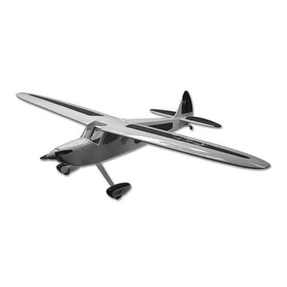
- Page 2 INTRODUCTION 2-Stroke - O.S. .46AXII (SIG Part# OSMG0548) Congratulations on your purchase of the SIG RASCAL 80 EG ARF kit. The 2-Stroke - O.S. .55AX (SIG Part# OSMG0557) legend of the RASCAL began with a small rubber powered free-flight 4-Stroke - FS56-a (SIG Part# OSMG0956) model in the 1950s.
- Page 3 ❑ (1) Nylon Control Horn Backing Plate materials available: ❑ (6) M2 x 15 mm Wood Screws A selection of glues - SIG Thin, Medium, & Thick CA Glue ❑ (6) M2 x 14 mm Machine Screws CA Accelerator ❑ (6) M2 Nuts CA De-bonder ❑...
-
Page 4: Covering Material
Fuel Tank for Glow Engine should be set to about 220 F - 250 F (104 C - 121 C) as measured on ❑ (1) Fuel Tank Body - 295cc (10 oz.) the bottom of the iron using a thermometer. ❑... -
Page 5: Wing Assembly
Fit the servo into the servo mount in the wing panel, (note that WING ASSEMBLY the servo is positioned so that the servo arm is at the forward end The wings are designed as a 2-piece system, with separate right and left toward the wing leading edge). - Page 6 Clip the metal clevis into the last hole in the nylon control horn. Lay the other end of the pushrod wire over the outer hole in the Turn the part over and glue the other side of the hinge. Continue servo arm.
-
Page 7: Fuselage Assembly
FUSELAGE ASSEMBLY INSTALL THE MAIN LANDING GEAR Locate the following parts from the kit contents: (1) Fuselage (1) Aluminum Main Landing Gear (3) M4 x 20 mm Socket-Head Bolts (3) M4 Split-Ring Lock Washers (2) 3" dia. Main Wheels (2) 4 mm dia. Axles with threaded bolt Head (2) 8 mm Hex Nuts;... - Page 8 (1) Tailwheel Assembly Use a fine line felt tip pen to mark some guide lines on (2) Coiled Steering Springs the stabilizer that will make it easy for you to realign the stab (1) Steering Arm after the glue is applied in the next step. You can now (2) M3 x 12 mm Screws remove the pins and take the stabilizer off the fuselage for (2) Split Lock Washers...
- Page 9 ❑ 19) Next we will mount the Tailwheel Assembly in place on the lower rear end of the fuselage. Begin by placing the three armed rudder steering horn on the bottom of the rudder. The front edge of the steering horn should be 1 / 4”...
- Page 10 metal clevis halfway onto the threads. Attach the steering springs to the three armed steering horn and Locate the pre-cut upper pushrod exit hole for the elevator on the tailwheel horn. the right side of the fuselage. Slide the end of the pushrod wire (without the clevis) into the exit hole and inside the pushrod sleeve built into the fuselage.
- Page 11 Locate the pull-pull hardware bag, and lay out the parts. Thread an M3 nut and a metal clevis onto the brass rigging coupler. Do this step four times. Make sure that the elevator servo is in neutral position and then adjust the metal clevis at the tail end as needed to get the Slide one of the crimp tubes onto the nylon coated braided steel elevator in perfect neutral position.
-
Page 12: Electric Power System
When the loops are pulled tight, crimp the middle 1/3 of the ELECTRIC POWER SYSTEM tube to lock the wire in place. At this point, connect metal clevis Skip this section if you’re using a glow engine power setup to the middle hole on one of the rudder control horns, and slide the pull-pull wire into the guide tube in the fuselage. - Page 13 Tack glue the firewall in place. Recheck once more to make sure that the front of the firewall is at the correct distance from the back of the motor mount box. That distance plus the length of your motor must equal 5-3/8”. When satisfied it is correct, glue the firewall securely to the rest of the motor mount box.
- Page 14 Arming Switch (SIG Part# MXACC6972) shown below. There are also arming switches built into some of ❑ 32) Mount the cowling on the fuselage with the four M3 x 10mm the advanced ESCs now on the market.
- Page 15 The cowl can now be permanently mounted to the fuselage. Slide the cowl back into position with the four pieces of tag board on the outside of the cowl. Carefully reposition the cowl and tape it in place with low-tack masking tape. Now drill the four cowl mounting holes through the cowl.
- Page 16 engine may require some alterations and/or specialized fittings (not Option #1) Cut one or more cooling slots in the bottom of the cowl as supplied). shown. A Dremel® Tool, or similar rotary hand-tool, with an assortment of bits is without a doubt the best tool to use For this section you will need the Fuselage and: for making cutout in the fiberglass cowling.
- Page 17 stopper and seal the stopper in the tank. Do not over tighten ❑ 37) Set your engine in place on the beams of the engine mounts. the screw as it can cause the tank to split. Attach three 6- Slide the engine forward or aft on the engine mounts until the inch lengths of silicone fuel tubing (not furnished) to the tank front of the engine's thrust washer is 5-3/8"...
- Page 18 you do not need access to that area. We recommend simply tack gluing the hatch in place with a couple small tabs of glue. Then seal over the seams with either clear tape or white covering material (not supplied). ❑ 43) 2-STROKE THROTTLE PUSHROD The first step is to install your throttle servo in the fuselage using the rubber grommets, eyelets, and screws that came with the servo.
- Page 19 Note: A Dremel® Tool, or similar powered hand-tool, with an Remove the tape, cowl, and tag board from the fuselage. Screw assortment of sanding bits is without a doubt the best tool to use for each of the four cowl screws into a hole and then remove the making holes in the fiberglass cowling.
-
Page 20: Install Side Windows
CONGRATULATIONS! Your RASCAL 80 EG ARF is completely assembled. However, it is NOT ready for flight! There are a few very critical pre-flight tasks we must perform before flying. These are extremely important and should be approached with patience and care. -
Page 21: Control Surface Travel
Wherever you put the balancing weight, make sure it cannot what a great looking airplane! come loose in flight! Because the RASCAL 80 EG ARF has so much wing area, adding balancing weight will have little effect on its flying ability. -
Page 22: Customer Service
SIG MFG. CO., INC. is committed to your success in both assembling product for his or her intended use and shall assume all risk and liability and flying the RASCAL 80 EG ARF. Should you encounter any problem in connection therewith. - Page 23 When that happens and the bottom rear corner of the hatch clears the front fuselage former, the hatch will lift back and off easily. SIG MFG CO., INC. 401 S. Front St. Montezuma, Iowa 50171 U.S.A. Copyright 2016 SIG MFG CO., INC. Printed in Vietnam *Also Available from SIG*...
Need help?
Do you have a question about the Rascal 80 eg and is the answer not in the manual?
Questions and answers