Table of Contents
Advertisement
Quick Links
Advertisement
Table of Contents

Related Manuals for Planet ADN-4101


Summary of Contents for Planet ADN-4101
- Page 1 802.11n Wireless ADSL 2/2+ Router ADN-4101...
- Page 2 Copyright Copyright 2011 by PLANET Technology Corp. All rights reserved. No part of this publication may be reproduced, transmitted, transcribed, stored in a retrieval system, or translated into any language or computer language, in any form or by any means, electronic, mechanical, magnetic, optical, chemical, manual or otherwise, without the prior written permission of PLANET.
- Page 3 Reorient or relocate the receiving antenna. Increase the separation between the equipment and receiver. Connect the equipment into an outlet on a circuit different from that to which the receiver is connected. Consult the dealer or an experienced radio technician for help. FCC Caution To assure continued compliance (example-use only shielded interface cables when connecting to computer or peripheral devices).
- Page 4 Revision User’s Manual for 802.11n Wireless ADSL 2/2+ Router Model: ADN-4101 Rev: 1.0 (Apr. 2011) Part No. EM-ADN4101_v1...
-
Page 5: Table Of Contents
Contents 1 Overview ......................1 Safety Precautions ................. 1 LEDs and Interfaces ................2 System Requirements ................4 Features ....................4 2 Hardware Installation ..................6 3 Web Configuration ................... 8 Accessing the Device ................8 General Configuration ................9 3.2.1 Wizard .................. - Page 6 3.4.3 Access Controls ..............74 3.4.4 Diagnostics ................78 3.4.5 Log Configuration ..............80 3.4.6 Logout ..................81 Status ....................81 3.5.1 Device Information ..............81 3.5.2 Wireless Clients ..............83 3.5.3 DHCP Clients ................83 3.5.4 Logs ..................84 3.5.5 Statistics ..................
-
Page 7: Overview
Overview The ADN-4101 supports multiple line modes. It provides four 10/100Base-TX Ethernet interfaces at the user end. The device provides high speed ADSL broadband connection to the Internet or Intranet for high-end users, such as net cafes and office users. It provides high performance access to the Internet, downstream up to 24 Mbps and upstream up to 1 Mbps. -
Page 8: Leds And Interfaces
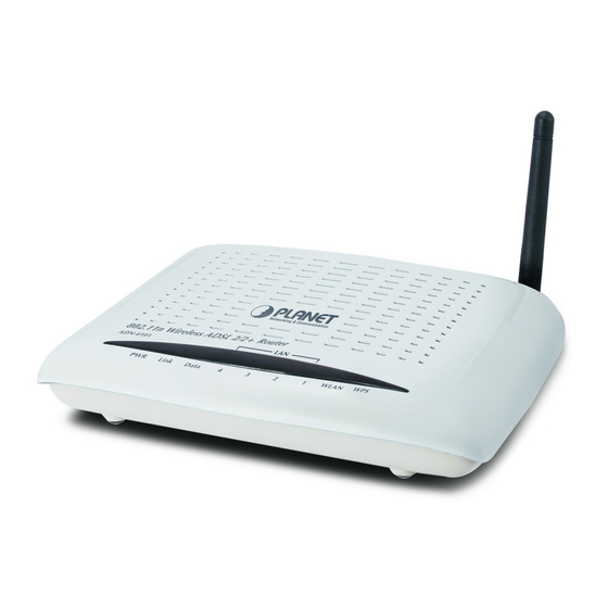
1.2 LEDs and Interfaces Front Panel Figure 1 Front panel The following table describes the LEDs of the device. Color Status Description The device is powered on and the Green initialization is normal. The power is off. The device is self-testing or self-testing is failed. - Page 9 Color Status Description The LAN connection is not established. The WLAN connection has been activated. Data is being transmitted through the WLAN Green Blinks WLAN interface. The WLAN connection is not activated. WPS is activated and the device is waiting Blinks Green for negotiation with the clients.
-
Page 10: System Requirements
Interface/Button Description Press the button and hold it for 3 or more than 3 seconds, to initialize WPS negotiation. ON/OFF Power switch, power on or off the device. 1.3 System Requirements Recommended system requirements are as follows: A 10Base-T/100Base-TX Ethernet card is installed on your PC. ... - Page 11 Virtual server Three-level user accounts Web user interface Telnet CLI System status displaying PPP session PAP, CHAP, and MS-CHAP IP filter IP QoS Remote access control Line connection status test ...
-
Page 12: Hardware Installation
Hardware Installation Step 1 Connect the LINE interface of the device and the Modem interface of the splitter with a telephone cable. Connect the phone set to the Phone interface of the splitter through a telephone cable. Connect the input cable to the Line interface of the splitter. The splitter has three interfaces: ... - Page 13 Figure 3 Connection diagram (without a telephone set before the splitter) Connection 2: Figure 4 shows the connection of the device, PC, splitter, and telephone set, when a telephone set is placed before the splitter. As illustrated in the following figure, the splitter is installed close to the device: Figure 4 Connection diagram (with a telephone set before the splitter) Note: When connection 2 is used, the filter must be installed close to the telephone...
-
Page 14: Web Configuration
Web Configuration This chapter describes how to configure the device by using the Web-based configuration utility. 3.1 Accessing the Device The following describes how to access the device for the first time in detail. Step 1 Open the Internet Explorer (IE) browser and enter http://192.168.1.1 in the address bar. -
Page 15: General Configuration
Click OK to log in again. Note: In the LAN, you can use either of the following two levels of user accounts (displayed in the user name/password format) to access the device: admin/admin and user/user. In the WAN, you can use one of the following three levels of user accounts (displayed in the user name/password format) to access the device: admin/admin, user/user, and support/support. - Page 16 Step 2 Click Setup Wizard. The page as shown in the following figure appears: There are four steps to configure the device. Click Next to continue. Step 3 Set the time and date. Then, click Next.
- Page 17 Step 4 Configure the Internet connection. Select the protocol and the encapsulation mode. Set the VPI and the VCI. If the Protocol is set to PPPoE or PPPoA, the page as shown in the following figure appears:...
- Page 18 You need to enter the user name and password for PPPoE or PPPoA dialup. If the Protocol is set to Dynamic IP, the page as shown in the following figure appears: If the Protocol is set to Static IP, the page as shown in the following figure appears:...
- Page 19 You need to enter the information of the IP address, subnet mask, and gateway. If the Protocol is set to Bridge, the page as shown in the following figure appears: After setting, click Next. Step 5 Configure the wireless network. Enter the information and click Next.
- Page 20 Step 6 View the configuration information of the device. To modify the information, click Back. To effect the configuration, click Next.
-
Page 21: Internet Setup
Note: In each step of the Wizard page, you can click Back to review or modify the previous settings or click Cancel to exit the wizard. 3.2.2 Internet Setup Choose Setup > Internet Setup. The page as shown in the following figure appears:... - Page 22 In this page, you can configure the WAN interface of the device. Click Add and the page as shown in the following figure appears: The following table describes the parameters in this page. Field Description ATM PVC CONFIGURATION Virtual Path Identifier (VPI) is the virtual path between two points in an ATM network.
- Page 23 Field Description Virtual Channel Identifier (VCI) is the virtual channel between two points in an ATM network. Its value range is from 32 to 65535 (0 to 31 is reserved for local management of ATM traffic). Select UBR with PCR, UBR without PCR, CBR, Non Service Category Realtime VBR, or Realtime VBR from the drop-down list.
-
Page 24: Wireless Setup
3.2.3 Wireless Setup This section describes the wireless LAN and some basic configuration. Wireless LANs can be as simple as two computers with wireless LAN cards communicating in a pear-to-pear network or as complex as a number of computers with wireless LAN cards communicating through access points that bridge network traffic to a wired LAN. - Page 25 In this page, you can configure the parameters of wireless LAN clients that may connect to the device. The following table describes the parameters in this page. Field Description Select or deselect the check box to enable or disable Enable Wireless the wireless function.
- Page 26 Field Description Select the wireless channel used by the device from Wireless Channel the drop-down list. You can select Auto Scan or a value from CH1—CH13. Auto Scan is recommended. Select the 802.11 mode of the device from the 802.11 Mode drop-down list.
- Page 27 If the Security Mode is set to WEP, the page as shown in the following figure appears: The following table describes the parameters in this page. Field Description You can select 64 bits or 128 bits from the drop-down WEP Key Length list.
- Page 28 Field Description If you select 64 bits, you need to enter 10 hexadecimal numbers or 5 characters. If you select 128 bits, you need to enter 26 hexadecimal numbers or 13 characters. Select the WEP key from the drop-down list. Its value Choose WEP Key range is 1—4.
- Page 29 The following table describes the parameters in this page. Field Description You can select Auto (WPA or WPA2)-PSK or Auto (WPA WPA Mode or WPA2)-Enterprise from the drop-down list. WPA Encryption You can select AES or TKIP+AES from the drop-down list. Group Key Set the interval for updating the key.
- Page 30 You need to enter the IP address, port, shared key of the RADIUS server. Click Apply to save the settings. WPA2 Only If the Security Mode is set to WPA2 only, the page as shown in the following figure appears:...
- Page 31 Parameters in this page are similar to those in the page for Auto (WPA or WPA2).Click Apply to save the settings. WPA Only If the Security Mode is set to WPA only, the page as shown in the following figure appears:...
-
Page 32: Local Network
Parameters in this page are similar to those in the page for Auto (WPA or WPA2). Click Apply to save the settings. 3.2.4 Local Network You can configure the LAN IP address according to the actual application. The preset IP address is 192.168.1.1. You can use the default settings and DHCP service to manage the IP settings of the private network. - Page 33 LAN, the IP address pool used for DHCP must be compatible with the IP address of the device. The IP address available in the DHCP IP address pool changes automatically if the IP address of the device changes. You can also enable the secondary LAN IP address. The primary and the secondary LAN IP addresses must be in different network segments.
- Page 34 DHCP Server and selected the Enable DHCP Relay to set the DHCP Relay IP address.And you can also set the perferrde and alternate DNS server. Click Apply to save the settings. In the DHCP CLIENT CLASS LIST page, you can set a IP address range for some specification device.
- Page 35 The following table describes the parameters in this page. Field Description Client Class Name Enter the Client Class name Min IP Address The IP Address for minimun Max IP Address The IP Address for maxmun DNS Address Enter the DNS Address with the client class In the LOCAL NETWORK page, you can assign LAN IP addresses for specific computers according to their MAC addresses.
-
Page 36: Time And Date
Field Description Select the check box to reserve the IP address for the Enable designated PC with the configured MAC address. Enter the computer name. It helps you to recognize the Computer Name PC with the MAC address. For example, Father’s Laptop. -
Page 37: Logout
In the TIME AND DATE page, you can configure, update, and maintain the time of the internal system clock. You can set the time zone that you are in and the network time protocol (NTP) server. You can also set daylight saving time to automatically adjust the time when needed. -
Page 38: Advanced Configuration
Click Logout to log out of the configuration page. 3.3 Advanced Configuration This section contains advanced features used for network management, security and administrative tools to manage the device. You can view the status and other information of the device, to examine the performance and troubleshoot. 3.3.1 Advanced Wireless This function is used to modify the standard 802.11g wireless settings. - Page 39 3.3.1.1 Advanced Settings In the ADVANCED WIRELESS page, click Advanced Settings. The page as shown in the following figure appears:...
- Page 41 The following table describes the parameters in this page. Field Description ADVANCED WIRELESS SETTINGS Select the transmission rate of the wireless network Transmission Rate from the drop-down list. Select the multicast transmission rate of the wireless Multicast Rate network from the drop-down list. You can select Lower or Higher.
- Page 42 Field Description Select whether toenable WMM. You can select Off or WMM Advertise Set the maximum number of clients that can be Max Clients connected to the AP at the same time. Its value range is 1—32. SSID1—3 Enable Wireless Select or deselect the check box to enable or disable Guest Network the wireless interface.
- Page 43 The following table describes the parameters in this page. Field Description Enter the MAC address of another device that is MAC Address included in MAC filtering. Click Apply to save the settings. 3.3.1.3 Security Settings In the ADVANCED WIRELESS page, click Security Settings. The page as shown in the following figure appears: Select the desired SSID from the drop-down list.
- Page 44 3.3.1.4 WPS Settings In the ADVANCED WIRELESS page, click WPS Setting. The WIRELESS WPS page as shown in the following figure appears: Enabled: The WPS service is enabled by default. Note: Ensure that the network card supports the WPS function. Field Description Select Mode...
-
Page 45: Port Forwarding
In the WIRELESS WPS page, click PBC. It has the same function of the WPS button on the side panel. This is an optional method on wireless clients. Note: You need a Registrar when using the PBC method in a special case in which the PIN is all zeros. - Page 46 Select a service for a preset application or enter the name in the Custom Server field. Enter an IP address in the Server IP Address field, to appoint the corresponding PC to receive forwarded packets. The port table displays the ports that you want to open on the device. The Protocol indicates the type of protocol used by each port.
-
Page 47: Dmz
3.3.3 Choose Advanced > DMZ. The page as shown in the following figure appears: In this page, you can enable a DMZ host. In this way, access from Internet to the WAN IP address of the device is forwarded to the DMZ host and network server of the internal LAN is protected. -
Page 48: Parental Control
3.3.4 Parental Control Choose Advanced > Parental Control. The PARENTAL CONTROL page as shown in the following figure appears: This page provides two useful tools for restricting Internet access. Block Website allows you to quickly create a list of websites that you wish to prevent users from accessing. - Page 49 Enter the website in the URL field. Select the time to block websites from the Schedule drop-down list, or select Manual Schedule and set the corresponding time and days. Click Apply to add the website to the BLOCK WEBSITE table. The page as shown in the following figure appears: 3.3.4.2 MAC Filter...
- Page 50 Click Add. The page as shown in the following figure appears: The following table describes the parameters in this page. Field Description Enter the name that identifies your configuration. For User Name example, kids. Current PC’s MAC Enter the MAC address of the computer that connects Address to the device.
-
Page 51: Filtering Options
Field Description Select the time of MAC filter from the drop-down list. Schedule You can select always or never. If you select this check box, you need to manually set Manual Schedule the time of MAC filtering. Enter the use name and MAC address. Select the corresponding time and days. Then, click Apply to add the MAC address to the BLOCK MAC ADDRESS table. - Page 52 3.3.5.1 IP Filtering In the Fitering Options page, click IP Filtering. The FIREWALL page as shown in the following figure appears: Click Add to add an IP filter. The page as shown in the following figure appears:...
- Page 53 Field Description Name Enter the name that identifies your configuration. Select LAN or the other connection from the drop-down Interface list. Type Select the In , Out or Both from the drop-down list. Default action Select the Permit or Drop from the drop-down list. Select the Local , Forward or Both from the Default Chain drop-down list.
- Page 54 Check the Enabled and specify at least one of the following criteria: protocol, source/destination IP address, subnet mask, and source/destination port. Then, click Apply to save the settings. Note: The settings apply only when the firewall is enabled.
- Page 55 3.3.5.2 Bridge Filtering In the FILTERING OPTIONS page, click Bridge Filtering. The page as shown in the following figure appears: This page is used to configure bridge parameters. In this page, you can modify the settings or view the information of the bridge and its attached ports. Click Add to add a bridge filter.
-
Page 56: Qos Configuration
Field Description drop-down list. You can select PPPoE, IPv4, IPv6, AppleTalk, IPX, NetBEUI, or IGMP. Destination MAC Enter the destination MAC address to be mapped. Address Source MAC Enter the source MAC address to be mapped. Address Select the frame direction to be mapped from the Frame Direction drop-down list. -
Page 57: Qos Global Option
QoS Global Option 3.3.6.1 In the QoS Configuration page, click QoS Global Option. The page as shown in the following figure appears: In this page, you can select or deselect the check box to enable or disable the Queuing Operation. 3.3.6.2 Queue Configuration In the QoS Configuration page, click Qos Queue Configuration. - Page 58 The device supports the following four priority levels: 1,2,3,4. Click Submit to save the settings. 3.3.6.3 Classification Configuration In the QoS Configuration page, click QoS Classification Configuration. Click Add and the page as shown in the following figure appears: The following table describes the parameters in this page. Field Description You can select Upstream Flow Classify or...
- Page 59 Field Description QoS classification. SPECIFY TRAFFIC CLASSIFICATION RULES Select the physical port of the packet from the Input Interface drop-down list. For example, ethernet1, ethernet2, ethernet3, and ethernet4. Source MAC Address Enter the source MAC address of the packet. Use mask 000000ffffff to mask the MAC address. 00 Source MAC Mask indicates not mapped and ff indicates mapped.
-
Page 60: Firewall Settings
3.3.7 Firewall Settings A denial-of-service (DoS) attack is one of the most common network attacks and is characterized by an explicit attempt by attackers to prevent legitimate users of a service from using that service. It usually leads to overload of system server or core dump of the system. - Page 61 The DNS system is, in fact, its own network. If one DNS server does not know how to translate a particular domain name, it asks another one, and so on, until the correct IP address is returned. Choose Advanced > DNS. The page as shown in the following figure appears: The following table describes the parameters in this page.
-
Page 62: Dynamic Dns
3.3.9 Dynamic DNS The device supports dynamic domain name service (DDNS). The dynamic DNS service allows a dynamic public IP address to be associated with a static host name in any of the many domains, and allows access to a specified host from various locations on the Internet. -
Page 63: Network Tools
Field Description Select the DDNS provider from the drop-down list. You DDNS provider can select DynDns.org, TZO, or GnuDIP. Enter the host name that you register with your DDNS Hostname provider. Select the interface that is used for DDNS service from Interface the drop-down list. -
Page 64: Port Mapping
Figure 5 This page contains the following function items: Port Mapping, IGMP Proxy, IGMP Snooping, UPnP, ADSL, SNMP, TR-069, Certificates, PPTP. 3.3.11 Port Mapping In the NETWORK TOOLS page, click Port Mapping. The page as shown in the following figure appears:... - Page 65 In this page, you can bind the WAN interface and the LAN interface to the same group. Click Add to add port mapping. The page as shown in the following figure appears: To create a mapping group, do as follows: Step 1 Enter the group name.
- Page 66 Step 2 Select interfaces from the Available Interfaces list and click the <- arrow button to add them to the Grouped Interfaces list, in this way, you can create the required mapping of the ports. The group name must be unique. Step 3 Click Apply to save the settings.
- Page 67 3.3.11.2 IGMP Snooping When IGMP snooping is enabled, only hosts that belong to the group receive the multicast packets. If a host is deleted from the group, the host cannot receive the multicast packets any more. In the NETWORK TOOLS page, click IGMP Snooping. The page as shown in the following figure appears: Click Apply to save the settings.
- Page 68 UPnP is widely applied in audio and video software. It automatically searches devices in the network. If you are concerned about UPnP security, you can disable it. Select the WAN and LAN interfaces at which you want to enable UPnP and click Apply to save the settings.
- Page 69 In this page, you can set the SNMP parameters. The following table describes the parameters in this page. Field Description Select or deselect the check box to enable or disable Enable SNMP Agent SNMP agent. Universal character to obtain the device information. It Read Community is similar to the password.
- Page 70 3.3.11.6 TR-069 In the NETWORK TOOLS page, click TR-069. The page as shown in the following figure appears: In this page, you can configure the TR-069 CPE. The following table describes the parameters in this page. Field Description You can select Disabled or Enabled to disable or TR069 Configuration enable TR-069 configuraion.
- Page 71 Field Description The interval of sending a request of connection to the Inform Interval TR069 server from the device. The path of the TR069 server to which the device ACS URL sends a request. The user name that the devices uses to log in to the ACS User Name TR069 server.
-
Page 72: Routing
Note: Before importing a certificate, you must synchronize the system time with time server. Otherwise, the certificate fails to be imported. Click Input Certificate to import a certificate. The page as shown in the following figure appears: 3.3.12 Routing Choose Advanced > Routing. The page as shown in the following page appears:... - Page 73 This page contains the following function items: Static Route, Policy Router and Default Gateway. 3.3.12.1 Static Route Choose Advanced > Routing and click Static Route. The page as shown in the following figure appears: This page displays the information of existing static routes. Click Add and the page as shown in the following figure appears:...
- Page 74 The following table describes the parameters in this page. Field Description Destination Network The destination IP address of the device. Address Subnet Mask The subnet mask of the destination IP address. Use Gateway IP The gateway IP address of the device. Address Select the interface of the static routing used by the Use Interface...
-
Page 75: Schedules
In this page, you can select the interfaces on your device that use RIP of the protocol used. If you enable RIP, the device communicates with other devices using the routing information protocol (RIP).Click Apply to save the settings. 3.3.12.3 Default Gateway Choose Advanced >... - Page 76 Click Add to add a schedule rule. The page as shown in the following figure appears: The following table describes the parameters in this page. Field Description Name Set the name of the schedule. You can select one, more, or all of the seven days in a Day(s) week.
-
Page 77: Nat
3.3.14 NAT Choose Advanced > NAT. The page as shown in the following figure appears: Traditional NAT would allow hosts within a Internal network to transparently access hosts in the external network, you can select Single IP or IP Range with the Internal and External IP type and enter the Internal and External IP address to decide witch Internal IP address transparently the specify External IP address. -
Page 78: Management
3.4 Management 3.4.1 System Choose Management > System Management. The System page as shown in the following figure appears: In this page, you can restart the device, back up the current settings to a file, update the backup file, and restore the factory default settings. The following table describes the buttons in this page. -
Page 79: Firmware Update
Button Description Reboot Restart the device. Specify the path to back up the current configuration in Backup Setting a configuration file on your computer. You can rename the configuration file. Click Browse… to select the configuration file of device Update Settings and click Update Settings to update the configuration of the device. -
Page 80: Access Controls
In this page, you can upgrade the firmware of the device. To update the firmware, do as follows: Step 1 Click Browse…to select the file. Step 2 Select Clear Config. Step 3 Click Update Firmware to update the configuration file. The device loads the file and reboots automatically. - Page 81 This page contains Account Password, Services, and IP Address. 3.4.3.1 Account Password In the ACCESS CONTROLS page, click Account Password. The page as shown in the following figure appears: Figure 6 In this page, you can change the password and set the time for automatic logout. You are recommended to change the default password to ensure the security of your network.
- Page 82 Field Description ACCOUNT PASSWORD Select a user name from the drop-down list to access Username the device. You can select admin, user. New Username Enter the new username. Current Password Enter the password of the user. New Password Enter the new password. Confirm Password Enter the new password again for confirmation.
- Page 83 In this page, you can enable or disable the services that are used by the remote host. For example, if telnet service is enabled at port 23, the remote host can access the device by telnet through port 23. Select the management services that you want to enable or disable at the LAN or WAN interface and click Apply to apply the settings.
-
Page 84: Diagnostics
Click Add. The page as shown in the following figure appears: Enter the IP address of the desired device in the IP Address field and click Apply to apply the settings. 3.4.4 Diagnostics Choose Management > Diagnosis. The page as shown in the following figure appears: This page contains WAN Diagonstics and Ping Diagnostics. - Page 85 3.4.4.2 Ping Diagnostics In the Diagnosis page, click Ping Diagnostics. The page as shown in the following figure appears:...
-
Page 86: Log Configuration
In this page, you can test the IP address on the same segment connect status of the device. Click Ping to run diagnostics. 3.4.5 Log Configuration Choose Management > Log Configuration. The SYSTEM LOG page as shown in the following figure appears: In this page, you can enable the log function. -
Page 87: Logout
3.4.6 Logout Choose Management > Logout. The page as shown in the following figure appears: Click Logout to log out of the configuration page. 3.5 Status In the Status page, you can view the system information and monitor the performance of the device. 3.5.1 Device Information Choose Status >... -
Page 89: Wireless Clients
The page displays the summary of the device status, including the system information, WAN connection information, wireless information, and local network information. 3.5.2 Wireless Clients Choose Status > Wireless Clients. The page as shown in the following page appears: The page displays authenticated wireless stations and their statuses. 3.5.3 DHCP Clients Choose Status >... -
Page 90: Logs
3.5.4 Logs Choose Status > Logs. The page as shown in the following figure appears: This page displays the system log. Click Refresh to refresh the system log shown in the box. 3.5.5 Statistics Choose Status > Statistics. The page as shown in the following figure appears:... - Page 91 This page displays the statistics information of the network and data transmission. The information helps technicians to identify whether the device is functioning properly. The information does not affect the functions of the device.
-
Page 92: Route Information
3.5.6 Route information Choose Status > Route Info. The page as shown in the following figure appears: The table displays destination routes commonly accessed by the network. 3.5.7 Logout Choose Staus > Logout. The page as shown in the following figure appears: Click Logout to log out of the configuration page.
Need help?
Do you have a question about the ADN-4101 and is the answer not in the manual?
Questions and answers