Rice Lake 120 Installation Manual
Digital weight indicator
Hide thumbs
Also See for 120:
- Installation manual (43 pages) ,
- Technical manual (42 pages) ,
- Technical manual (42 pages)
Table of Contents
Advertisement
Quick Links
Advertisement
Table of Contents

Related Manuals for Rice Lake 120


Summary of Contents for Rice Lake 120
- Page 1 Digital Weight Indicator Installation Manual 76699...
-
Page 3: Table Of Contents
Course descriptions and dates can be viewed at www.rlws.com or obtained by calling 715-234-9171 and asking for the training department. © 2004 Rice Lake Weighing Systems. All rights reserved. Printed in the United States of America. Specifications subject to change without notice. - Page 4 7.8 Specifications ..............36 120 Limited Warranty..........................37...
-
Page 5: About This Manual
Authorized distributors and their employees accomplished using the indicator front panel keys, the can view or download this manual from the EDP command set, or Version 3.0 or later of the Rice Lake Weighing Systems distributor ª Revolution conÞguration utility. See Section 3.1 on site at www.rlws.com... -
Page 6: Front Panel Keypad
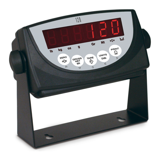
ZERO PRINT GROSS UNITS TARE Units Figure 1-1. 120 Front Panel LED Annunciators display uses a set of eight LED annunciators to provide additional information about the value being displayed: ¥ (gross) and (net) annunciators are lit to show whether the displayed weight is a gross or net weight. -
Page 7: Indicator Operations
See Section 3.2.2 for more information about conÞguring primary and secondary display units. Secondary Unit Primary Unit none lb / lb lb / kg lb / oz lb / g lb / kg kg / lb kg / kg kg / oz kg / g lb / kg oz / lb... -
Page 8: Panel Mode Operations
) key to set the value and return to the menu level above. Figure 1-2 Enter TARE shows the structure of the panel mode menu. TIME DATE CONSNU CONSTU SHOW HOUR MINUTE SECOND SHOW YEAR MONTH number number hh.mm.ss yy.mm.dd Figure 1-2. Panel Mode Menu Structure 120 Installation Manual... -
Page 9: Installation
The setup switch is protected by a cover plate and secured with a Þllister head screw (not shown in Figure 2-1). 9VDC ADAPTER COMMUNICATIONS LOAD CELL PORT 1 PORT 2 SETUP SWITCH Figure 2-1. Back View of 120 Enclosure, Showing Load Cell and Communications Connectors and Setup Switch Location Installation... -
Page 10: Serial Communications
(CPU board Table 2-3. Replacement Parts is mounted to front half of enclosure; power, communications, and load cell connections all connect to the bottom of the CPU board.) 6. Reverse steps to reassemble enclosure. 120 Installation Manual... -
Page 11: Configuration
Configuration To conÞgure the indicator, the indicator must be placed in setup mode. The setup switch is accessed by removing the left Þllister head SETUP SWITCH screw on underside of the enclosure and removing the rectangular switch cover plate. Switch position is changed by inserting a screwdriver into the access hole and pressing the switch. -
Page 12: Edp Command Configuration
VERSION Version Display installed software version number. Table 3-1. 120 Menu Summary Four front panel keys are used as directional keys to navigate through the menus in setup mode. The UNITS ( ) keys scroll left and right (horizontally) on the same menu level;... -
Page 13: Menu Structures And Parameter Descriptions
Menu Structures and Parameter Descriptions The following sections provide graphic representations of the menu structures. In the actual menu structure, the settings you choose under each parameter are arranged horizontally. To save page space, menu choices are shown in vertical columns. The factory default setting appears at the top of each column. Most menu diagrams are accompanied by a table that describes all parameters and parameter values associated with that menu. - Page 14 Digital filter cutout sensitivity. Specifies the number of consecutive readings that must fall 16OUT outside the filter threshold (DFTHRH parameter) before digital filtering is suspended. If 32OUT NONE is selected, the filter is always enabled. 64OUT 128OUT 2OUT 4OUT Table 3-2. ConÞguration Menu Parameters 120 Installation Manual...
- Page 15 CONFIG Menu Parameter Choices Description DFTHRH NONE Digital filter cutout threshold. Specifies the filter threshold, in display divisions. When a 0.1DD specified number of consecutive scale readings (DFSENS parameter) fall outside of this 0.2DD threshold, digital filtering is suspended. If NONE is selected, the filter is always enabled. 0.5DD 10DD 20DD...
-
Page 16: Format Menu
UNITS MULT MULEXP DSPRAT 250MS Display rate. Sets the update rate for displayed values. Values are in milliseconds (MS) or 500MS seconds (SEC). 750MS 1SEC 1500MS 2SEC 2500MS 3SEC 4SEC 6SEC 8SEC Table 3-3. Format Menu Parameters 120 Installation Manual... - Page 17 FORMAT Menu Parameter Choices Description Level 3 submenus Primary Units (PRIMAR Parameter) DECPNT 888888 Decimal point location. Specifies the location of the decimal point or dummy zeroes in the 8.88888 primary unit display. Value should be consistent with local legal requirements. 88.8888 888.888 8888.88...
-
Page 18: Calibration Menu
Press Enter to remove an offset value from the zero and span calibrations. Use this parameter only after WZERO and WSPAN have been set. See Section 4.1 on page 21 for more information about using this parameter. Table 3-4. Calibration Menu Parameters 120 Installation Manual... -
Page 19: Serial Menu
3.2.4 Serial Menu See Section 7.2 on page 29 for information about the serial data format. PROGRM PFORMT CONFIG FORMAT CALIBR SERIAL TIME DATE VERS PRINT BAUD BITS TERM BAUD BITS TERM ECHO 9600 8NONE 9600 8NONE CR/LF CR/LF 1200 19200 7ODD 7ODD... - Page 20 Selects number of data bits and parity of data transmitted from the printer port. 7ODD 7EVEN 7SPACE TERM CR/LF Termination character. Selects termination character for data sent from the printer port. Table 3-5. Serial Menu Parameters (Continued) 120 Installation Manual...
-
Page 21: Program Menu
3.2.5 Program Menu PROGRM PFORMT CONFIG FORMAT CALIBR SERIAL TIME DATE VERS PWRUPM REGULA CONSNU CONSTU NTEP DELAY OIML number number CANADA NONE Figure 3-7. ProgramMenu PROGRM Menu Parameter Choices Description Level 2 submenus PWRUPM Power up mode. In GO mode, the indicator goes into operation immediately after a brief power DELAY up display test. -
Page 22: Print Format Menu
See Section 6.0 on page 27 for information about custom print formatting. PROGRM PFORMT CONFIG FORMAT CALIBR SERIAL TIME DATE VERS EDIT INSERT DELETE 00_@40 0 1 _ N 4 E x x _ _ 0 0 Position ASCII Value Character Figure 3-8. Print Format Menu 120 Installation Manual... -
Page 23: Time Menu
3.2.7 Time Menu Time can also be set by the operator in panel mode. See Section 1.4.2 on page 4. PROGRM PFORMT CONFIG FORMAT CALIBR SERIAL TIME DATE VERS SHOW HOUR MINUTE SECOND 00.00.00 display time 00–59 00–59 00–23 Figure 3-9. Time Menu TIME Menu Parameter Choices... -
Page 24: Version Menu
The VERS menu is used to check the software version installed in the indicator. There are no parameters associated with the Version menu: when selected, the indicator displays the installed software version number. and the indicator model PROGRM PFORMT CONFIG FORMAT CALIBR SERIAL TIME DATE VERS Software version Figure 3-11. Version Menu 120 Installation Manual... -
Page 25: Calibration
Calibration ª can be calibrated using the front panel, EDP commands, or the Revolution conÞguration utility. Each method consists of the following steps: ¥ Zero calibration ¥ Entering the test weight value ¥ Span calibration ¥ Optional rezero calibration for test weights using hooks or chains. The following sections describe the calibration procedure for each of the calibration methods. -
Page 26: Edp Command Calibration
2. Send the WZERO EDP command to calibrate conÞguration mode. zero. The indicator displays while *CAL* calibration is in progress. NOTE: During EDP command calibration, the *CAL* message remains on the display. The response is returned when calibration is complete. 120 Installation Manual... -
Page 27: Edp Commands
EDP Commands 5.1.3 Reporting Commands indicator can be controlled by a personal computer or remote keyboard connected to the Reporting commands (Table 5-3) send speciÞc indicator EDP port. Control is provided by a set of information to the EDP port. These commands can be EDP commands that can simulate front panel key used in both conÞguration mode and normal mode. - Page 28 Table 5-5. FORMAT EDP Commands Command Description Values WZERO Zero calibration — WVAL Test weight value test_weight_value WSPAN Span calibration — REZERO Rezero — LC.CD Set deadload coefficient value LC.CW Set span coefficient value Table 5-6. CALIBR EDP Commands 120 Installation Manual...
- Page 29 Command Description Values EDP.BAUD EDP port baud rate 1200, 2400, 4800, 9600, 19200, 38400 EDP.BITS EDP port data bits/parity 8NONE, 7ODD, 7SPACE, 7EVEN EDP.TERM EDP port termination character CR/LF, CR EDP.ECHO EDP port echo ON, OFF PRN.BAUD Printer port baud rate 1200, 2400, 4800, 9600 PRN.BITS Printer port data bits/parity...
-
Page 30: Saving And Transferring Data
Þle. Communication between the PC and indicator will be lost once the indicator receives settings for baud rate (BAUD parameter) or data bits and parity (BITS parameter) that do not match those conÞgured for the PC. 120 Installation Manual... -
Page 31: Print Formatting
Gross, net, and tare weights are 9 digits in length, including A8,50,0,5,1,1,N,”@G” sign (10 digits with decimal point), followed by a space and @M A8,120,0,5,1,1,N,”@T” a two-digit units identifier. Total field length with units A8,190,0,5,1,1,N,”@N”@M identifier is 12 (or 13) characters. -
Page 32: Using The Front Panel
PFORMT CONFIG FORMAT CALIBR SERIAL TIME DATE VERS EDIT INSERT DELETE 00_@40 0 1 _ N 4 E x x _ _ 0 0 Position ASCII Value Character Figure 6-1. PFORMT Menu, Showing Alphanumeric Character Entry Procedure 120 Installation Manual... -
Page 33: Appendix
Positive weight value too large to be displayed (> 999999) (top LED segments lit Table 7-1. 120 Error Messages Continuous Output (Stream) Format Figure 7-1 shows the continuous output format sent to the EDP or printer port when the STREAM parameter (SERIAL menu) is set to either EDP or PRN. -
Page 34: Front Panel Display Characters
Front Panel Display Characters Figure 7-2 shows the 7-segment LED character set used to display alphanumeric characters on the front panel. < & > Õ Figure 7-2. 120 Display Characters 120 Installation Manual... -
Page 35: Ascii Character Chart
ASCII Character Chart Use the decimal values for ASCII characters listed in can send or receive any ASCII character Tables 7-2 and 7-3 when specifying print format value (decimal 0Ð255), but the indicator display is strings on the PFORMT menu. The actual limited to numbers, upper-case, unaccented letters, character printed depends on the character mapping and a few special characters. - Page 36 € Ç Ç • È º ƒ ± ¾ ³ ® £ ™ ó š õ ˜ ¸ ž » • ° Ø · … † ¢ £ ´ Ä Table 7-3. ASCII Character Chart (Part 2) 120 Installation Manual...
-
Page 37: Conversion Factors For Secondary Units
Conversion Factors for Secondary Units has the capability to mathematically convert a weight into many different types of units and instantly Primary Unit x Multiplier Secondary Unit display those results with a press of the key. UNITS ounces (oz) 28.3495 grams Secondary units can be speciÞed on the FORMAT menu using the SECNDR parameter, or by using EDP... -
Page 38: Digital Filtering
Þltering is set higher to counter low frequency transients. suspended. Set DFTHRH to NONE to turn off ReconÞgure as necessary to Þnd the lowest the Þlter override. effective value for the DFSENS parameter. 120 Installation Manual... -
Page 39: Test Mode
Test Mode In addition to normal and setup modes, test mode To enter test mode, press and hold the setup switch. provides a number of diagnostic functions for the After about three seconds, the test mode display including: automatically shifts to the Þrst test menu function, A/DTST ¥... -
Page 40: Specifications
IRFI Protection Signal, excitation, and sense lines protected by capacitor bypass OIML Digital Specifications R76-2 Test Certificate Microcomputer Intel MCS-52 with 16K EEPROM @ Accuracy Class : 3 000 18.432 MHz Digital Filters 3 filters, software selectable 120 Installation Manual... -
Page 41: 120 Limited Warranty
120 Limited Warranty Rice Lake Weighing Systems (RLWS) warrants that all RLWS equipment and systems properly installed by a Distributor or Original Equipment Manufacturer (OEM) will operate per written speciÞcations as conÞrmed by the Distributor/OEM and accepted by RLWS. All systems and components are warranted against defects in materials and workmanship for one year.
Need help?
Do you have a question about the 120 and is the answer not in the manual?
Questions and answers