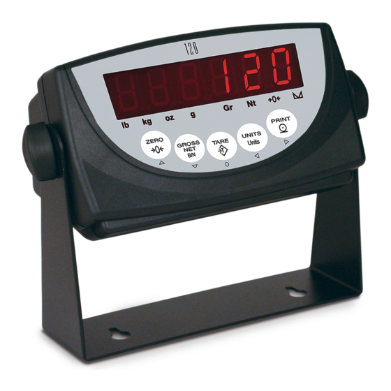
Rice Lake 120 Installation Manual
Digital weight indicator
Hide thumbs
Also See for 120:
- Installation manual (41 pages) ,
- Technical manual (42 pages) ,
- Technical manual (42 pages)
Table of Contents
Advertisement
Advertisement
Table of Contents

Related Manuals for Rice Lake 120


Summary of Contents for Rice Lake 120
- Page 1 Digital Weight Indicator Version 1.0 Installation Manual 76699...
-
Page 3: Table Of Contents
Course descriptions and dates can be viewed at www.ricelake.com or obtained by calling 715-234-9171 and asking for the training department © 2006 Rice Lake Weighing Systems. All rights reserved. Printed in the United States of America. Specifications subject to change without notice. - Page 4 7.8 Specifications ..............36 120 Limited Warranty..........................37...
-
Page 5: About This Manual
Authorized distributors and their employees accomplished using the indicator front panel keys, the can view or download this manual from the EDP command set, or Version 3.0 or later of the Rice Lake Weighing Systems distributor ™ Revolution configuration utility. See Section 3.1 on site at www.ricelake.com... -
Page 6: Front Panel Keypad
See Section 3.1.3 on page 8 for information about using the front panel keys in configuration mode. Figure 1-1. 120 Front Panel LED Annunciators display uses a set of eight LED annunciators to provide additional information about the value being displayed: •... -
Page 7: Indicator Operations
See Section 3.2.2 on page 12 for more information about configuring primary and secondary display units. Secondary Unit Primary Unit none lb / lb lb / kg lb / oz lb / g lb / kg kg / lb kg / kg kg / oz kg / g lb / kg... -
Page 8: Panel Mode Operations
Note: To enter a 2 digit month, the lower digit must be a “1” then the upper digit is incremented to “1”. The lower digit can then be changed to 0, 1 or 2 as required. TIME DATE CONSNU CONSTU SHOW HOUR MINUTE SECOND SHOW YEAR MONTH number number hh.mm.ss yy.mm.dd Figure 1-2. Panel Mode Menu Structure 120 Installation Manual... -
Page 9: Installation
Available PORT 1 PORT 2 SETUP SWITCH Setup Switch Figure 2-1. Back View of 120 Enclosure, Showing Load Cell DB-9 Connector, Communications Connectors and Setup Switch Location 2.2.1 Serial Communications The serial communications cable attaches to the male Port 1 D-Sub connector, Port 1 (see Figure 2-1 on page 5). -
Page 10: Serial Communications
Table 2-2. Load Cell Connector (Port 2) Pin Assignments Table 2-3. J1 Pin Assignments with Load Cell Cord Grip –EXC –SEN –SIG POWER +SIG +SEN SERIAL +EXC COMMUNICATIONS Figure 2-2. CPU Board, Showing Location of J1 Load Cell Connector 120 Installation Manual... -
Page 11: Enclosure Disassembly
Enclosure Disassembly Replacement Parts Use a wrist strap to ground yourself and Table 2-4 lists replacement parts for the indicator. Caution protect components from electrostatic discharge (ESD) when working inside the Description indicator enclosure. 78609 CPU Board If the indicator enclosure must be opened for maintenance, do the following: 78610 Switch panel membrane... -
Page 12: Configuration
R e v o l u t i o n I I I downloading of indicator configuration data. This capability allows configuration data to be retrieved from one indicator, edited, then downloaded to another. 120 Installation Manual... -
Page 13: Edp Command Configuration
VERSION Version Display installed software version number. Table 3-1. 120 Menu Summary Four front panel keys are used as directional keys to navigate through the menus in setup mode. The UNITS ( ) keys scroll left and right (horizontally) on the same menu level;... -
Page 14: Menu Structures And Parameter Descriptions
0.5D 100% FS+1D FS+9D SMPRAT DIGFL1 DIGFL2 DIGFL3 DFSENS DFTHRH 8OUT NONE 15HZ 0.1DD 7.5HZ 16OUT 32OUT 3.75HZ 0.2DD 30HZ 0.5DD 64OUT 128OUT 1OUT 2OUT 10DD 4OUT 20DD 50DD 100DD 200DD 250DD Figure 3-3. Configuration Menu 120 Installation Manual... - Page 15 CONFIG Menu Parameter Choices Description Level 2 submenus Set programmable gain amplifier for load cell sensitivity: –0.5 mV/V to 4.5 mV/V PGA = 1 –0.2 mV/V to 2.2 mV/V PGA = 2 –0.1 mV/V to 1.1 mV/V PGA = 4 –0.5 mV/V to 0.6 mV/V PGA = 8 GRADS...
- Page 16 (DFSENS parameter) fall outside of this 0.2DD threshold, digital filtering is suspended. If NONE is selected, the filter is always enabled. 0.5DD 10DD 20DD 50DD 100DD 200DD 250DD Table 3-2. Configuration Menu Parameters (Continued) 120 Installation Manual...
-
Page 17: Format Menu
3.2.2 Format Menu CONFIG FORMAT CALIBR SERIAL PROGRM PFORMT TIME DATE VERS PRIMAR SECNDR DSPRAT DECPNT DSPDIV UNITS DECPNT DSPDIV UNITS MUL T MULEXP 250MS 500MS 88888. 8 dec_position 750MS 888888 0.45359 8.88888 number 1SEC 888888 88.8888 8.88888 1500MS 888.888 88.8888 2SEC 8888.88... - Page 18 Multiplier decimal shift. Specifies a divisor used to shift the decimal position in the secondary units multiplier value. Use the left and right arrow keys to shift the decimal point within the displayed MULT value. Table 3-3. Format Menu Parameters (Continued) 120 Installation Manual...
-
Page 19: Calibration Menu
3.2.3 Calibration Menu See Section 4.0 on page 21 for calibration procedures. CONFIG FORMAT CALIBR SERIAL PROGRM PFORMT TIME DATE VERS WZERO WVAL WSPAN REZERO *CAL* CAL* *CAL* 10000 Display and edit Press Enter to Display and edit span calibration remove offset from zero calibration Display and edit... -
Page 20: Serial Menu
Specifies settings for baud rate, data bits, termination characters, and end-of-line delay used by BITS the printer port. TERM STREAM Selects the serial port used for continuous transmission. See Section 7.2 on page 29 for information about the continuous data format. Table 3-5. Serial Menu Parameters 120 Installation Manual... - Page 21 SERIAL Menu Parameter Choices Description STMDLY 250MS Stream delay. Specifies the delay, seconds (SEC) or milliseconds (MS), inserted between stream 500MS frames. 1SEC 2SEC 4SEC 8SEC 15SEC NONE PRNDES Print destination. Selects the port for data transmission when the PRINT key is pressed or the KPRINT EDP command is sent.
-
Page 22: Program Menu
Changing either CONSTU or CONSNU immediately resets the consecutive number used for printing. CONSTU Consecutive number start up value. Specifies the initial consecutive number (CONSNU) value number used when the indicator is powered on. Table 3-6. Program Menu Parameters 120 Installation Manual... -
Page 23: Print Format Menu
3.2.6 Print Format Menu See Section 6.0 on page 27 for information about custom print formatting. PROGRM PFORMT CONFIG FORMAT CALIBR SERIAL TIME DATE VERS EDIT INSERT DELETE 00_@40 0 1 _ N 4 E x x _ _ 0 0 Position ASCII Value... -
Page 24: Time Menu
DATE Menu Parameter Choices Description Level 2 submenus SHOW YY.MM.DD Displays current date in YY.MM.DD format YEAR year (YY) Set year (two digits, 00–99) MONTH month (MM) Set month day (DD) Set day Table 3-8. Date Menu Parameters 120 Installation Manual... -
Page 25: Version Menu
3.2.9 Version Menu The VERS menu is used to check the software version installed in the indicator. There are no parameters associated with the Version menu: when selected, the indicator displays the installed software version number. and the indicator model PROGRM PFORMT CONFIG... -
Page 26: Calibration
( REZERO) 6. The function is used to remove a REZERO calibration offset when hooks or chains are used to hang the test weights. Note: If no other apparatus was used to hang the test 120 Installation Manual... -
Page 27: Edp Command Calibration
EDP Command Calibration To calibrate the indicator using EDP commands, the 3. Place test weights on the scale and use the WVAL command to enter the test weight indicator EDP port must be connected to a terminal or value in the following format: personal computer. -
Page 28: Edp Commands
Reporting commands (Table 5-2) send specific information to the EDP port. These commands can be used in both configuration mode and normal mode. Command Function DUMPALL List all parameter values VERSION Write software version Table 5-2. EDP Reporting Commands 120 Installation Manual... - Page 29 Command Description Values Programmable gain amplifier 1, 2, 4, 8 GRADS Graduations 1–100 000 ZTRKBND Zero track band OFF, 0.5D, 1D, 3D ZRANGE Zero range 1.9%, 100% MOTBAND Motion band 1D, 2D, 3D, 5D, 10D, 20D, 50D, OFF OVRLOAD Overload FS+2%, FS+1D, FS+9D, FS SMPRAT Sample rate...
- Page 30 Consecutive number start-up value 0–999 999 Table 5-7. PROGRM EDP Commands Command Description Values WWPF Print characters of format string See Section 6.0 on page 27 for detailed information Print hex values of format string Table 5-8. PFORMT EDP Commands 120 Installation Manual...
-
Page 31: Saving And Transferring Data
Saving and Transferring Data Connecting a personal computer to the EDP port allows you to save indicator configuration data to the PC or to download configuration data from the PC to an indicator. The following sections describe the procedures for these save and transfer operations. -
Page 32: Print Formatting
NOTE: After entering the WWPF=0 or WPF=0 command, you The default print format is shown below: must begin entering the print format. If no data is entered, the command times out, resulting in a blank format. @G <CR> @M @T <CR> @N @M <CR> 120 Installation Manual... -
Page 33: Using The Front Panel
6.2.2 Using the Front Panel If you have no access to equipment for communication through the EDP port or are working at a site where such equipment cannot be used, you can use the PFORMT menu (see Figure 6-1) to customize the print format. Using the PFORMT menu, you can edit the print format string by changing the hex values of the ASCII characters in the format string. - Page 34 120 Installation Manual...
-
Page 35: Appendix
Positive weight value too large to be displayed (> 999999) (top LED segments lit Table 7-1. 120 Error Messages Continuous Output (Stream) Format Figure 7-1 shows the continuous output format sent to the EDP or printer port when the STREAM parameter (SERIAL menu) is set to either EDP or PRN. -
Page 36: Front Panel Display Characters
Front Panel Display Characters Figure 7-2 shows the 7-segment LED character set used to display alphanumeric characters on the front panel. Figure 7-2. 120 Display Characters 120 Installation Manual... -
Page 37: Ascii Character Chart
ASCII Character Chart Use the decimal values for ASCII characters listed in can send or receive any ASCII character Tables 7-2 and 7-3 when specifying print format value (decimal 0–255), but the indicator display is strings on the PFORMT menu. The actual limited to numbers, upper-case, unaccented letters, character printed depends on the character mapping and a few special characters. - Page 38 ¡ ∈ Ä « ∩ Å » ≡ É ± æ ≥ Æ ≤ ô ö ò ÷ û ≈ ù ° ÿ • Ö Ü ¢ £ ¥ ƒ Table 7-3. ASCII Character Chart (Part 2) 120 Installation Manual...
-
Page 39: Conversion Factors For Secondary Units
Conversion Factors for Secondary Units has the capability to mathematically convert a weight into many different types of units and instantly Primary Unit x Multiplier Secondary Unit display those results with a press of the key. UNITS ounces (oz) 28.3495 grams Secondary units can be specified on the FORMAT menu using the SECNDR parameter, or by using EDP... -
Page 40: Digital Filtering
Reconfigure as necessary to find the lowest suspended. Set DFTHRH to NONE to turn off effective value for the DFSENS parameter. the filter override. 120 Installation Manual... -
Page 41: Test Mode
Test Mode In addition to normal and setup modes, test mode To enter test mode, press and hold the setup switch. provides a number of diagnostic functions for the After about three seconds, the test mode display including: automatically shifts to the first test menu function, DTST •... -
Page 42: Specifications
3 filters, software selectable Environmental Operating Temperature –10 to +40°C (legal); Approval TC6736 –10 to +50°C (industrial) : 5 000 Storage Temperature –25 to +70°C Humidity 0–95% relative humidity Altitude 2000 m (6500 ft) maximum Power Adaptor 120 Installation Manual... -
Page 43: 120 Limited Warranty
120 Limited Warranty Rice Lake Weighing Systems (RLWS) warrants that all RLWS equipment and systems properly installed by a Distributor or Original Equipment Manufacturer (OEM) will operate per written specifications as confirmed by the Distributor/OEM and accepted by RLWS. All systems and components are warranted against defects in materials and workmanship for one year.
Need help?
Do you have a question about the 120 and is the answer not in the manual?
Questions and answers