Table of Contents
Advertisement
Advertisement
Table of Contents

Related Manuals for Permobil Corpus 3G


Summary of Contents for Permobil Corpus 3G
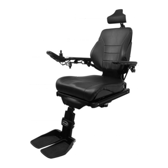
- Page 1 SERVICE MANUAL Corpus 3G Seat system for electric wheelchair...
-
Page 3: Table Of Contents
Contents Contents Introduction ......................5 Technical support ....................5 Spare parts & accessories ................. 5 Disposal ......................5 Warranty & servicing ..................5 Maintenance ....................... 5 Product approval ....................5 Adjustment ......................6 Adjusting the seat depth ................... 6 Adjusting the seat width .................. 10 Adjusting the backrest height ................ -
Page 5: Adjustment
Adjustment Adjusting the seat depth Adjustment For this task the following tools are necessary: 1 Allen key 5 mm Adjusting the seat depth The seat depth can be adjusted to suit different users. There are nine fixed levels, each 25 mm apart. Adjustment of the seat depth is performed by mounting the front section of the Seat frame incl. - Page 6 Adjustment Adjusting the seat depth Adjustment of the front section of the Seat frame (Leg rest position) 4. Remove the five screws marked (L) securing the Seat frames front section, see fig below. 5. Adjust the seat depth by moving the front section of the seat frame to the required position. The rails with which the seat depth is adjusted are marked with the settings for each potential position.
- Page 7 Adjustment Adjusting the seat depth Adjustment of the rear section of the Seat frame (Back rest position). 7. Remove the seven screws marked (B) securing the Seat frames rear section, see fig. below. 8. Adjust the seat depth by moving the rear section of the seat frame to the required position. The rails with which the seat depth is adjusted are marked with the settings for each potential position.
- Page 8 Adjustment Adjusting the seat depth 10. Mount UniTrack rails of a suitable length for the seat depth setting. See the table on 43. The rails are each held in place by two screws. See the illustration. Use a torque wrench to tighten the screws.
-
Page 9: Adjusting The Seat Width
Adjustment Adjusting the seat width Adjusting the seat width For this task the following tools are necessary: 1 Allen key 5 mm The seat width can be adjusted to give the user optimal comfort. There are three fixed levels, each 25 mm apart. 1. -
Page 10: Adjusting The Backrest Height
Adjustment Adjusting the backrest height Adjusting the backrest height For this task the following tools are necessary: 1 Allen key 3 mm The backrest height can be adjusted to give the user optimal comfort. Adjustment is possible by moving the locking mechanism on the upper section of the backrest between six fixed stages 25 mm apart. -
Page 11: Adjusting The Armrest Height
Adjustment Adjusting the armrests Adjusting the armrest height For this task the following tools are necessary: 1 Allen key 5 mm The height of the armrest can be adjusted to provide the user with optimal comfort. 1. Undo the four screws holding the armrest at its current height. See the illustration below. m WARNING! Do not subject the armrests to load when adjusting them. -
Page 12: Adjusting The Armrest Angle
Adjustment Adjusting the thigh support and trunk support Adjusting the armrest angle The angle of the armrest can be easily adjusted to provide the user with optimal comfort. 1. Adjust the armrest angle by turning the adjustment bars. See the illustration. m WARNING! Do not subject the armrests to load when adjusting them. -
Page 13: Adjusting The Armrest Width
Adjustment Adjusting the armrests Adjusting the armrest width For this task the following tools are necessary: 1 Allen key 5 mm The distance between the armrests can be adjusted to give the user optimal comfort. 1. Loosen the screw for armrest width adjustment approximately 3 turns. -
Page 14: Adjusting The Thigh Support
Adjustment Adjusting the thigh support and trunk support Adjusting the thigh support The position of the thigh support can be adjusted forwards or backwards to give the user optimal comfort. Slide the thigh support forwards or backwards to the desired position. The position of the thigh support can be adjusted Adjusting the trunk support height For this task the following tools are necessary:... -
Page 15: Repairs
Repairs Replacing a UniTrack rail Repairs For this task the following tools are necessary: 1 Allen key 5 mm Replacing a UniTrack rail UniTrack rails are available in five different lengths that are used depending on the seat depth selected. See the table on 43. Removal 1. -
Page 16: Replacing Seat Plates
Repairs Replacing seat plates Replacing seat plates For this task the following tools are necessary: Seat plates are available in five different lengths 1 Allen key 3 mm that are used depending on the seat depth selected. See the table on 43. Removal 1. -
Page 17: Replacing Backrest Plates
Repairs Replacing backrest plates Replacing backrest plates Backrest plates are available in three different widths to fit most users. If you change the size of the backrest plates you will also have to change the cushion to one that is a suitable size. See the table on 43. - Page 18 Repairs Replacing backrest plates Mounting 1. Mount the lower backrest plate by lining up the four "keyholes" on the locking devices and then sliding the plate straight down. The lower backrest plate is secured by means of four locking devices 2.
-
Page 19: Replacing The Armrest Height Adjustment Mechanism
Repairs Replacing the armrest height adjustment mechanism Replacing the armrest height adjustment mechanism For this task the following tools are necessary: Removal 1 Allen key 3 mm 1 Allen key 5 mm 1. Remove the backrest plates. For a detailed description, see 18. - Page 20 Repairs Replacing the armrest height adjustment mechanism 6. Remove the backrest profile, which is secured using two screws on the left and right. See the illustration. Remove by undoing the screws and pulling the backrest profile straight up. The backrest profile is secured using two screws on the left and right 7.
- Page 21 Repairs Replacing the armrest height adjustment mechanism Mounting 1. Push the threaded rod into the backrest profile and at the same time screw on the driver (1). See the illustration below. 2. Apply threadlocker (Loctite 2701) to the ends of the threaded rod and fit the two end pieces (2 & 3) onto the threaded rod.
- Page 22 Repairs Replacing the armrest height adjustment mechanism 5. Remount the backrest profile by fitting the bracket into the profile groove on the left and right sides. Slide the profile downwards until the stop on the bracket is touching the end of the backrest profile on both the left side and the right.
-
Page 23: Replacing The Manual Legrest Adjustment Unit
Repairs Replacing the manual legrest adjustment Replacing the manual legrest For this task the following tools are necessary: adjustment unit 1 Allen key 5 mm 1 Allen key 8 mm Removal 1. Switch off the main power switch on the control m WARNING! panel. -
Page 24: Replacing The Manual Backrest Adjustment Unit
Repairs Replacing the manual backrest adjustment Replacing the manual backrest For this task the following tools are necessary: adjustment unit 1 Allen key 5 mm 1 Allen key 8 mm Removal 1. Switch off the main power switch on the control panel. -
Page 25: Replacing The Legrest Actuator
Repairs Replacing the legrest actuator Replacing the legrest actuator For this task the following tools are necessary: 1 Allen key 5 mm Removal 1 Allen key 8 mm 1. Switch off the main power switch on the control panel. 2. Remove the UniTrack rail from the right side m WARNING! of the seat. -
Page 26: Replacing The Backrest Actuator
Repairs Replacing the backrest actuator Replacing the backrest actuator For this task the following tools are necessary: 1 Allen key 5 mm Removal 1 Allen key 8 mm 1. Switch off the main power switch on the control panel. m WARNING! 2. -
Page 27: Replacing The Seat Angle Mechanism
Repairs Replacing the seat angle mechanism Replacing the seat angle For this task the following tools are necessary: mechanism 1 Allen key 5 mm 1 Allen key 8 mm Removal 1. Switch off the main power switch on the control panel. - Page 28 Repairs Replacing the seat angle mechanism 6. Remove the four screws that hold the seat angle mechanism in place. See the illustration below. The seat angle mechanism can be mounted in three different positions, depending on the chassis the seat is mounted on and the depth of the seat. Note the position the seat angle mechanism is mounted in for future reference.
- Page 29 The mounting position for the seat angle mechanism depends on the chassis model and the seat depth setting. The table shows mounting positions for standard model wheelchairs; accessories such as height-adjustable footplates or a respirator shelf may affect the mounting position. Contact Permobil in case of doubt.
- Page 30 Repairs Replacing the seat angle mechanism 2. Mount the seat using the six screws. Have someone help you lift the seat and then hold it in place while the screws are inserted. Use a torque wrench to tighten the screws. Tightening torque 9.8 Nm.
-
Page 31: Replacing The Fixed Seat Mounting Plate
Repairs Replacing the fixed seat mounting plate Replacing the fixed seat mounting For this task the following tools are necessary: plate 1 Allen key 5 mm 1 Allen key 8 mm Removal 1. Switch off the main power switch on the control panel. - Page 32 Repairs Replacing the fixed seat mounting plate 5. Remove the four screws that hold the seat mounting plate in place. See the illustration below. The seat mounting plate can be mounted in three different positions, depending on the chassis the seat is mounted on and the depth of the seat.
- Page 33 The mounting position for the seat mounting plate depends on the chassis model and the seat depth setting. The table shows mounting positions for standard model wheelchairs; accessories such as height-adjustable footplates or a respirator shelf may affect the mounting position. Contact Permobil in case of doubt.
- Page 34 Repairs Replacing the fixed seat mounting plate 2. Mount the seat using the six screws. Have someone help you lift the seat and then hold it in place while the screws are inserted. Use a torque wrench to tighten the screws. Tightening torque 9.8 Nm.
-
Page 35: Replacing The Adapter Plate
Repairs Replacing the adapter plate Replacing the adapter plate For this task the following tools are necessary: Between the seat lift and the seat angle mechanism 1 Allen key 5 mm or the fixed seat mounting plate there is an adapter 1 Allen key 8 mm plate. - Page 36 The mounting position for the seat mounting plate/seat angle mechanism depends on the chassis model and the seat depth setting. The table shows mounting positions for standard model wheelchairs; accessories such as height-adjustable footplates or a respirator shelf may affect the mounting position. Contact Permobil in case of doubt.
-
Page 37: Replacing A Legrest
Repairs Replacing a legrest Replacing a legrest For this task the following tools are necessary: 1 Allen key 5 mm 1 Allen key 8 mm m WARNING! Do not subject the legrest to load during mounting or removal. Risk of crushing. Remove the legrest's top cover by carefully Removal pulling it straight out... - Page 38 Repairs Replacing a legrest Mounting 1. Mount the legrest using the two screws and spacers. See the illustration on the previous . Use a torque wrench to tighten the screws. Tightening torque 24 Nm. 2. Mount the front bracket of the manual adjustment unit/actuator.
-
Page 39: Replacing A Legrest Strap
Repairs Replacing a legrest strap Replacing a legrest strap For this task the following tools are necessary: 1 Allen key 3 mm 1 Steel ruler m WARNING! Do not subject the legrest to load during mounting or removal. Risk of crushing. Lift up the legrest's top cover Removal 1. -
Page 40: Replacing The Legrest Slide Bushings
Repairs Replacing the legrest slide bushings Replacing the legrest slide bushings For this task the following tools are necessary: 1 Allen key 3 mm m WARNING! Do not subject the legrest to load during mounting or removal. Risk of crushing. The slide bushing in the upper section of the Removal legrest is attached using two screws. -
Page 41: Replacing The Footplate
Repairs Replacing the footplate Replacing the footplate For this task the following tools are necessary: 1 Allen key 5 mm Removal 1. Switch off the main power switch on the control panel. m WARNING! 2. Remove the screw holding the footplate in place. -
Page 42: Recommended Cushions, Seat Plates And Unitrack Rails
Repairs Recommended cushions, seat plates and UniTrack rails Recommended seat cushions, seat plates and UniTrack rails Seat depth Seat width Cushion Cushion Seat plate UniTrack rail (mm.) (mm.) (Length) (Width) (Length) (Length) 420/470/520 420 mm. = Sitsbredd 370 mm. 370 mm. 420/470/520 420 mm. - Page 43 Repairs Cabling overview...
-
Page 44: Cabling Overview
Repairs Cabling overview Cabling overview 45 45... -
Page 45: Index
Index Index Accessories ......... 5 Legrest ..........38 Actuator - Backrest ......28 Legrest slide bushings ....41 Actuator - legrest ......27 Legrest strap ........42 Adapter plate ........36 Armrest width ........14 Armrest height ........12 Maintenance ........5 Armrest height adjustment Manual backrest adjustment ...
Need help?
Do you have a question about the Corpus 3G and is the answer not in the manual?
Questions and answers