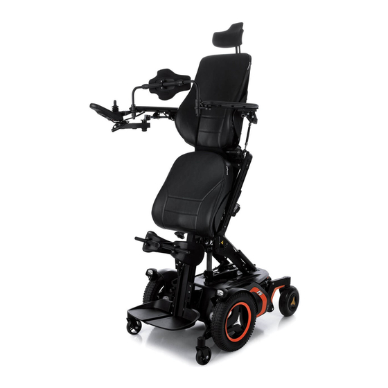
Permobil F5 Corpus Owner's Manual
Power wheelchair
Hide thumbs
Also See for F5 Corpus:
- User manual (294 pages) ,
- Service manual (204 pages) ,
- Assembly instruction manual (26 pages)
Table of Contents
Advertisement
Quick Links
Advertisement
Chapters
Table of Contents
Troubleshooting

Related Manuals for Permobil F5 Corpus


Summary of Contents for Permobil F5 Corpus
- Page 1 Owner’s Manual English F5 Corpus...
- Page 3 We congratulate you on your choice of power wheelchair. Our goal is for you to continue to feel satisfied with your choice of both vendor and wheelchair. Your Permobil is designed to give you highest possible comfort and safety and to meet the requirements regarding safety and environment.
- Page 4 Text Produced and published by Permobil AB Edition:1, 2014-09 Order no: 205356-UK-0...
- Page 6 6466 GZ Kerkrade Netherlands Tel: +31 (0)45 564 54 80 Fax: +31 (0)45 564 54 81 Email:: info@permobil.nl The Permobil Group’s Head Office Permobil AB Box 120 861 23 Timrå Sweden Tel: +46 60 59 59 00 Fax: +46 60 57 52 50 E-mail: info@permobil.se...
-
Page 7: Table Of Contents
Owner's Manual Permobil F5 Corpus Contents CONTENTS Important Information about this Owner’s Manual ................... 9 Safety instructions ............................13 Design and function............................ 33 Settings and adjustments .......................... 49 R-net Control Panel With LCD Monochrome Display................63 R-net Control Panel With LCD Color Display ..................79 R-net LED Control Panel ........................... - Page 8 Contents Owner's Manual Permobil F5 Corpus Index ................................179...
-
Page 9: Important Information About This Owner's Manual
We reserve the right to make changes to the product without prior notice. If you are visually impaired, this document can be viewed in PDF format at www.permobil.com or alternatively ordered in large text. - Page 10 Always state the seats serial number when contacting Permobil to ensure that the correct information is provided. Spare parts & accessories Spare parts and accessories must be ordered through Permobil. The expected service life of this product is 7 years. Scrapping Contact Permobil for information about scrapping agreements in force.
- Page 11 If an incident occurs please contact your nearest Permobil representative. Normally the same person you contacted at purchase day. To prepare this contact there is a link on our homepage, on the internet, at www.permobil.com. Open up your country page and the contact page. Here is the needed contact information and a guidance document in what in- formation we need to investigate the incident.
- Page 12 Owner's Manual Permobil F5 Corpus Important Information about this Owner’s Manual...
-
Page 13: Safety Instructions
Permobil is not responsible for personal injuries or property damage resulting from any person’s failure to follow the warnings and instructions in this manual. Permobil is not responsible for injuries or damage resulting from failure to ex- ercise good judgment. -
Page 14: Safety Instructions
Owner's Manual Permobil F5 Corpus Safety instructions Attension! Throughout this manual the following symbol will be used to note items that have significant importance to safety concerns: WARNING! Please use extreme caution where this warning symbol appears. Failure to observe warnings can lead to personal injury and property damage, including damage to the wheelchair. - Page 15 • that all products ordered are included in the delivery, including operating instructions and possible other documen- tation. If you suspect that something is missing, then contact your supplier or Permobil for more information as soon as possible.
- Page 16 CAUTION! Operation Permobil recommends the use of wheelchair lights at all times user is riding near public rights of way. Use extreme caution when driving near unprotected ledges, drop-offs or on elevated surfaces. Unintended movement or excessive speed in these areas can lead to personal injury or property damage.
- Page 17 Owner's Manual Permobil F5 Corpus Safety instructions CAUTION! Operation Do not use the wheelchair to pull any kind of objects and never hang excessive weights on the backrest. Doing so could lead to personal injury and property damage, including damage to the wheelchair.
- Page 18 WARNING! Weight Limitations The maximum user weight for your Permobil is set forth in the specification section in this Owner’s Manual for current seat model. Operation of the wheelchair by users who exceed the maximum allowable user weight can lead to personal injury and property damage, including damage to the wheelchair, as well as voiding any applicable warranty to the wheelchair.
- Page 19 Owner's Manual Permobil F5 Corpus Safety instructions CAUTION! Operation - Inclines When driving downhill, select the slowest speed and proceed with caution. Driving down an incline can shift the user’s center of gravity forward. If the wheelchair rolls faster than you would like, stop the wheelchair by releasing the joystick and begin descending again at a slower speed.
- Page 20 Do not put your Permobil in freewheel mode while on an incline. This could cause the wheelchair to roll on its own, causing injury and property damage, including damage to the wheelchair.
- Page 21 Owner's Manual Permobil F5 Corpus Safety instructions CAUTION! Driving in Darkness Driving in the dark may only be done if your wheelchair is equipped with functioning lighting in the front and the back, or as per the applicable national or local traffic regulations.
- Page 22 Owner's Manual Permobil F5 Corpus Safety instructions WARNING! Center of Balance The possibility of this wheelchair tipping and the point where this wheelchair will tip forward, back or to the side depends on its center of balance. Please note that the following factors can affect the wheelchair’s center of balance: •...
- Page 23 Owner's Manual Permobil F5 Corpus Safety instructions CAUTION! Positioning Belt Permobil positioning belts are designed to position the user only and will not protect you in an accident. You may even receive further injury from the belts.
- Page 24 Owner's Manual Permobil F5 Corpus Safety instructions WARNING! Support Wheels If your wheelchair is equipped with support wheels, they must always be mounted when the wheelchair is being driven.
- Page 25 Overextending this distance can cause user to overexert, lose balance, or fall. Permobil recommends that users transfer in the presence of or with the assistance of an attendant. Use caution when bending or reaching.
- Page 26 • Permobil positioning belts are designed to position the user only and not to protect you in the event of a motor vehicle accident. The positioning belts do not replace use of a vehicle mounted restraint.
- Page 27 CAUTION! Driving in Extreme Climate Conditions Permobil’s wheelchairs are designed to withstand most adverse weather conditions, however to minimize the risk of being caught in difficult situations you should avoid using the wheelchair outdoors during, for example, severe cold, heavy rain or thick snow.
- Page 28 Permobil to perform such service on Permobil products. Incorrect settings could result in unsafe operation of the wheelchair and could cause the chair to become unstable or uncontrollable. Such modifications may also void the wheelchair’s warranty.
- Page 29 WARNING! Safety Circuits Permobil products are equipped with safety circuits. Inhibit circuits prevent the wheelchair from driving under certain conditions. Speed reduction circuits limit the wheelchair’s maximum speed under certain conditions. Limit switch circuits limit the wheelchair’s functions under certain circumstances. Overload protection circuits shut the wheelchair off in case of an overload.
- Page 30 Owner's Manual Permobil F5 Corpus Safety instructions WARNING! Filling Air into tires Check at regular intervals that the wheelchair’s tires have the prescribed tire pressure. Incorrect tire pressure can cause deteriorating stability and maneuverability. The prescribed tire pressure is 200-250 kPa (2-2.5 bar).
- Page 31 If you experience that the wheelchair in any manner is not behaving as expected or if you suspect that something is wrong: Stop driving as soon as possible, shut off the wheelchair and contact your service contact or Permobil for more information.
- Page 32 Owner's Manual Permobil F5 Corpus Safety instructions...
-
Page 33: Design And Function
Owner's Manual Permobil F5 Corpus Design and function DESIGN AND FUNCTION General ..................... 34 Shock absorber ................35 Drive package.................. 36 Wheels ....................36 Lights and reflectors ............... 37 Batteries ................... 38 Electronics..................39 Electric Seat Functions..............40 Manual Seat Functions..............41 Other Adjustment Options ............. -
Page 34: General
Owner's Manual Permobil F5 Corpus Design and function General The Permobil F5 Corpus is an electric front-wheel drive wheelchair for outdoor and indoor driving. It is intended for people with physical disabilities. The wheelchair consists of a chassis and a seat. The chassis contains the wheelchair’s electronics, power sup-... -
Page 35: Shock Absorber
The wheelchair is equipped with two shock absorbers. Adjustment Adjustment should to be performed by personnel who are well-acquainted with the design and functionality of the wheelchair. When adjustment is needed, contact your nearest Authorized Permobil Service Center. Figure 2. Drive package and shock absorbers. -
Page 36: Drive Package
Owner's Manual Permobil F5 Corpus Design and function Drive package The Permobil F5 Corpus is equipped with a drive package for each drive wheel. The drive package consists of an electric motor with a drive gear and magnetic wheel lock. -
Page 37: Lights And Reflectors
Owner's Manual Permobil F5 Corpus Design and function Lights and reflectors The wheelchair is equipped with reflectors on the front, rear and sides. Front/rear lights and turn indicators are optional. Figure 3. Front Reflectors Figure 4. Rear Reflectors Figure 5. Side Reflectors... -
Page 38: Batteries
Owner's Manual Permobil F5 Corpus Design and function Batteries The wheelchair’s batteries are located under the covers of the chassis. Both of the batteries are easily accessible for maintenance and replacement. WARNING! Be careful when using metal objects when working with batteries. A short- circuit can easily cause an explosion. -
Page 39: Electronics
Owner's Manual Permobil F5 Corpus Design and function Electronics Main fuse The is equipped with an automatic main fuse, which can be reset when it has been triggered. It also functions as a battery isolator and is controlled (ON/OFF) via the lever located in front of the left battery cover. -
Page 40: Electric Seat Functions
Owner's Manual Permobil F5 Corpus Design and function Electric Seat Functions The electric seat functions are driven by an electric actuator which is step- lessly controlled from the wheelchair control panel. Available functions may vary depending on how the seat is equipped. -
Page 41: Manual Seat Functions
Owner's Manual Permobil F5 Corpus Design and function Manual Seat Functions The seat can be adjusted manually by adjusting manual locking tubes with quick-acting locks in a number of fixed positions. Available functions may vary depending on how the seat is equipped. -
Page 42: Other Adjustment Options
Owner's Manual Permobil F5 Corpus Design and function Other Adjustment Options The control panel, arm rest, foot plates and other accessories such as calf rest, thigh support, trunk support, head rest, etc. have manual adjustment and setting options. -
Page 43: Electric Seat Lift
Owner's Manual Permobil F5 Corpus Design and function Electric Seat Lift Permobil can be fitted with an elec- trically controlled seat lift that allows the seat to be raised steeples in or- der to adjust its height to tables, benches, etc. -
Page 44: Electric Seat Tilt
Owner's Manual Permobil F5 Corpus Design and function Electric Seat Tilt The electrically controlled seat tilt makes it possible to set the suitable seat angle within the operating range. Figure 12. Electric Seat Tilt... -
Page 45: Electric Backrest
Owner's Manual Permobil F5 Corpus Design and function Electric Backrest The back angle can be adjusted (via the Recline Control), allowing the consumer to set a recline angle as needed within the operating range. WARNING! There is a risk of pinching accidents when using the electrical functions of the seat. -
Page 46: Electric Legrest
Owner's Manual Permobil F5 Corpus Design and function Electric Legrest The legrests can be elevated to a desired angle within the operating range. Figure 14. Electric Legrest... -
Page 47: Manual Seat Functions - Legrest Angle
Owner's Manual Permobil F5 Corpus Design and function Manual Seat Functions - Legrest Angle The angle of the leg rest is adjusted via an adjustable locking tube with a quick-acting lock in a number of fixed positions. 1. Pull out the quick-acting lock's... -
Page 48: Manual Seat Functions - Backrest Recline
Owner's Manual Permobil F5 Corpus Design and function Manual Seat Functions - Backrest Recline The angle of the back rest is ad- justed via an adjustable locking tube with a quick-acting lock in a number of fixed position. 1. Pull out the quick-acting lock's... -
Page 49: Settings And Adjustments
Owner's Manual Permobil F5 Corpus Settings and adjustments SETTINGS AND ADJUSTMENTS Positioning Belt................50 Legrest Cover .................. 52 Leg rest Length................53 Foot plate height................54 Foot plate angle................55 Arm rest height ................56 Arm rest angle ................. 57 Arm rest height/angle .............. -
Page 50: Positioning Belt
Owner's Manual Permobil F5 Corpus Settings and adjustments Positioning Belt Fitting the Positioning Belt There is an accessory rail on both sides of the seat frame for mounting such items as the positioning belt. Mount the positioning belt in the upper track of the rail. - Page 51 Settings and adjustments WARNING! Permobil positioning belts are designed to position the user only and not to protect you in the event of a motor vehicle accident. The positioning belts do not replace use of a vehicle mounted restraint. Always wear your positioning belt while in your wheelchair.
-
Page 52: Legrest Cover
Owner's Manual Permobil F5 Corpus Settings and adjustments Legrest Cover Remove the leg rest cover by undoing the two screws and then pulling the cover directly forward. See the illustration. Fit by pushing the cover into place and then securing it with the two screws. -
Page 53: Leg Rest Length
Owner's Manual Permobil F5 Corpus Settings and adjustments Leg rest Length The leg rest length can be adjusted continuously and secured using two lock- ing screws. 1. Remove the leg rest cover. See description above. 2. Undo the leg rest's two inner locking screws. See the illustration. -
Page 54: Foot Plate Height
Owner's Manual Permobil F5 Corpus Settings and adjustments Foot plate height The height of the foot plates can be adjusted individually and steplessly. They are secured using the two outer locking screws. 1. Remove the leg rest cover. See the description on the previous page. -
Page 55: Foot Plate Angle
Owner's Manual Permobil F5 Corpus Settings and adjustments Foot plate angle The angle of the foot plates is ad- justed using stop screws under each foot plate. 1. Tilt up the foot plates/plate. 2. Undo the lock nut. 3. Set to the required angle by screwing the screw in or out. -
Page 56: Arm Rest Height
Owner's Manual Permobil F5 Corpus Settings and adjustments Arm rest height The height of the arm rest can be ad- justed for optimal comfort. The scale on the back of the back- rest shows the current height setting for the arm rests. -
Page 57: Arm Rest Angle
Owner's Manual Permobil F5 Corpus Settings and adjustments Arm rest angle The arm rest angle can easily be ad- justed for optimal comfort. 1. Loosen the two nuts securing the position of the adjustment bar. 2. Adjust the arm rest angle by turn- ing the adjustment bar. -
Page 58: Arm Rest Height/Angle
Owner's Manual Permobil F5 Corpus Settings and adjustments Arm rest height/angle The arm rest height/angle is normally adjusted as described on pages 56 - 57. However, for special needs, the arm rests can be adjusted individually for users who want a left and right arm rest at different heights and/or angles. This adjustment can only be made for special needs. - Page 59 Owner's Manual Permobil F5 Corpus Settings and adjustments WARNING! When the screw is removed, the armrests angle setting is released. Support the armrest from underneath with one hand at the front edge as the screw is removed. Be careful, there is a risk of crushing.
-
Page 60: Head Rest (Accessory)
Owner's Manual Permobil F5 Corpus Settings and adjustments Head rest (accessory) This head rest has expanded adjustment options to give the user optimal comfort. The head rest can also be removed/remounted while preserving the same setting. Removal 1. Undo the handle (3) on the rear of the back rest. See fig. 28. -
Page 61: Rotatable Panel Holder
Owner's Manual Permobil F5 Corpus Settings and adjustments Rotatable panel holder The location of the control panel can be adjusted lengthwise for the opti- mal driving position. It is also possi- ble to adjust the angle of the panel sideways to facilitate getting in and out. -
Page 62: Parallel Panel Holder
Owner's Manual Permobil F5 Corpus Settings and adjustments Parallel Panel Holder The location of the control panel can be adjusted lengthwise for the opti- mal driving position. The panel can also be pushed out to the side, diag- onally back to facilitate getting in and out. -
Page 63: R-Net Control Panel With Lcd Monochrome Display
Owner's Manual Permobil F5 Corpus R-net Control Panel With LCD Monochrome Display R-NET CONTROL PANEL WITH LCD MONOCHROME DISPLAY General ..................... 64 Charger Socket................65 Function Buttons ................66 Jack Sockets..................69 Display ....................70 Locking/unlocking the Control System......... 71... -
Page 64: General
Owner's Manual Permobil F5 Corpus R-net Control Panel With LCD Monochrome Display General The Control Panel consists of a joy- stick, function buttons and a Display. At the back of the panel you also find the Charger Socket and two Jack Sockets. -
Page 65: Charger Socket
Owner's Manual Permobil F5 Corpus R-net Control Panel With LCD Monochrome Display Charger Socket WARNING! The wheelchair’s warranty will be voided if any device other than a battery charger supplied with the wheelchair, or the lock key is connected into the control panels charger socket. -
Page 66: Function Buttons
Owner's Manual Permobil F5 Corpus R-net Control Panel With LCD Monochrome Display Function Buttons On the control panel there are a total of 10 Function Buttons. On/Off Button The On/Off button applies power to the control system electronics, which in turn supply power to the wheelchair’s motors. -
Page 67: Mode Button
Owner's Manual Permobil F5 Corpus R-net Control Panel With LCD Monochrome Display Mode Button The Mode button allows the user to navigate through the available operating Modes for the control system. The available modes are dependant on pro- gramming and the range of auxiliary output devices connected to the control system. - Page 68 Owner's Manual Permobil F5 Corpus R-net Control Panel With LCD Monochrome Display Lights Button and LED NOTE! Only active if the wheelchair is provided with lights This button activates and de-activates the wheelchair’s lights. Depress the Figure 40. Lights Button and LED button to turn the lights on and depress the button again to turn them off.
-
Page 69: Jack Sockets
Owner's Manual Permobil F5 Corpus R-net Control Panel With LCD Monochrome Display Jack Sockets The External On/Off Switch Jack (1) allows the user to turn the control sys- tem on and off using an external device, such as a buddy button. -
Page 70: Display
Owner's Manual Permobil F5 Corpus R-net Control Panel With LCD Monochrome Display Display The status of the control system can be understood by observing the display. The control system is on when the display is backlit. Screen Symbols The Drive screen for the R-net has common components, which will always appear, and components which will only appear under certain conditions. -
Page 71: Locking/Unlocking The Control System
Owner's Manual Permobil F5 Corpus R-net Control Panel With LCD Monochrome Display Locking/unlocking the Control System The Control System can be locked in one of two ways. Either using a button sequence on the keypad or with a physical Key. How the Control system is locked depends on how your system is programmed. - Page 72 Owner's Manual Permobil F5 Corpus R-net Control Panel With LCD Monochrome Display Key Locking To lock the wheelchair with a key lock: • Insert and remove a PGDT supplied key into the Charger Socket on the Joystick Module. • The wheelchair is now locked.
-
Page 73: Seat Functions
Owner's Manual Permobil F5 Corpus R-net Control Panel With LCD Monochrome Display Seat functions Not applicable to all seat models On some seats the electrical functions can be controlled with the help of the control panel joystick. Some models are equipped with three memory loca- tions. - Page 74 Owner's Manual Permobil F5 Corpus R-net Control Panel With LCD Monochrome Display Maneuvering the seat CAUTION! If the symbol ”M” appears together with the seat icon, this means that a memory function has been activated. Move the joystick to the left or right to choose a seat function instead.
- Page 75 Owner's Manual Permobil F5 Corpus R-net Control Panel With LCD Monochrome Display Memory The control system on some seats have three memory locations for seat po- sitions. Each memory location can store the position of the seat’s adjustment device. This means that it is easy to retrieve a seat position saved earlier.
- Page 76 Owner's Manual Permobil F5 Corpus R-net Control Panel With LCD Monochrome Display Saving position to memory 1. Set the seat’s electrical functions to the desired mode. 2. If not activated, activate the seat/ memory function by pressing the ”Mode” button one or more times until a seat icon appears in the control panel display.
- Page 77 Owner's Manual Permobil F5 Corpus R-net Control Panel With LCD Monochrome Display Return to drive mode Press the ”Mode” button one or more times until a stand- ard display image with speed indicator appears in the control panel display - see fig. 47.
- Page 78 Owner's Manual Permobil F5 Corpus R-net Control Panel With LCD Monochrome Display...
-
Page 79: R-Net Control Panel With Lcd Color Display
Owner's Manual Permobil F5 Corpus R-net Control Panel With LCD Color Display R-NET CONTROL PANEL WITH LCD COLOR DISPLAY General ..................... 80 Charger Socket................81 Function Buttons ................82 Jack Sockets..................85 Display ....................86 Locking/unlocking the Control System......... 92... -
Page 80: General
Owner's Manual Permobil F5 Corpus R-net Control Panel With LCD Color Display General The Control Panel consists of a joy- stick, function buttons and a display. At the front of the panel is the Charg- er Socket. Two Jack Sockets are lo- cated on the bottom of the panel. -
Page 81: Charger Socket
Owner's Manual Permobil F5 Corpus R-net Control Panel With LCD Color Display Charger Socket WARNING! The wheelchair’s warranty will be voided if any device other than a battery charger supplied with the wheelchair, or the lock key is connected into the control panels charger socket. -
Page 82: Function Buttons
Owner's Manual Permobil F5 Corpus R-net Control Panel With LCD Color Display Function Buttons On the control panel there are a total of 10 Function Buttons. On/Off Button The On/Off button applies power to the control system electronics, which in turn supply power to the wheelchair’s motors. - Page 83 Owner's Manual Permobil F5 Corpus R-net Control Panel With LCD Color Display Mode Button The Mode button allows the user to navigate through the available operating Modes for the control system. The available modes are dependant on pro- gramming and the range of auxiliary output devices connected to the control system.
- Page 84 Owner's Manual Permobil F5 Corpus R-net Control Panel With LCD Color Display Lights Button and LED NOTE! Only active if the wheelchair is provided with lights This button activates and de-activates the wheelchair’s lights. Depress the Figure 60. Lights Button and LED button to turn the lights on and depress the button again to turn them off.
-
Page 85: Jack Sockets
Owner's Manual Permobil F5 Corpus R-net Control Panel With LCD Color Display Jack Sockets The External On/Off Switch Jack (1) allows the user to turn the control sys- tem on and off using an external device, such as a buddy button. -
Page 86: Display
Owner's Manual Permobil F5 Corpus R-net Control Panel With LCD Color Display Display The status of the control system can be understood by observing the display. The control system is on when the display is backlit. Screen Symbols The Drive screen for the R-net has common components, which will always appear, and components which will only appear under certain conditions. -
Page 87: Speed Indicator
Owner's Manual Permobil F5 Corpus R-net Control Panel With LCD Color Display Battery Indicator This displays the charge available in the battery and can be used to alert the user of the status of the battery. Figure 65. Battery Indicator Steady: This indicates that all is well. - Page 88 Owner's Manual Permobil F5 Corpus R-net Control Panel With LCD Color Display In Focus When the control system contains more then one method of direct control, such as a secondary Joystick Module or a Dual Attendant Module, then the Module that has control of the wheelchair will display the In Focus symbol.
- Page 89 Owner's Manual Permobil F5 Corpus R-net Control Panel With LCD Color Display Motor Temperature This symbol is displayed when the control system has intentionally reduced the power to the motors, in order to protect them against heat damage. Figure 72. Motor Temperature...
- Page 90 Owner's Manual Permobil F5 Corpus R-net Control Panel With LCD Color Display Installation menu The installation menu permits the user to set the clock, the display bright- ness, background color etc. Access the menu by holding down the keys for higher and lower maximum speed simultaneously.
- Page 91 Owner's Manual Permobil F5 Corpus R-net Control Panel With LCD Color Display Distance measurement (Distance) (Distance measurement (Distance): Select "Distance" in the menu. Move the joystick to the right to go to the menu for setting distance measurement. Then select "Total distance", "Trip", "Distance display" or "Reset" by moving the joystick up or down.
-
Page 92: Locking/Unlocking The Control System
Owner's Manual Permobil F5 Corpus R-net Control Panel With LCD Color Display Locking/unlocking the Control System The Control System can be locked in one of two ways. Either using a button sequence on the keypad or with a physical Key. How the Control system is locked depends on how your system is programmed. - Page 93 Owner's Manual Permobil F5 Corpus R-net Control Panel With LCD Color Display Key Locking To lock the wheelchair with a key lock: • Insert and remove a PGDT supplied key into the Charger Socket on the Joystick Module. • The wheelchair is now locked.
-
Page 94: Seat Functions
Owner's Manual Permobil F5 Corpus R-net Control Panel With LCD Color Display Seat functions Not applicable to all seat models On some seats the electrical functions can be controlled with the help of the control panel joystick. Some models are equipped with three memory loca- tions. - Page 95 Owner's Manual Permobil F5 Corpus R-net Control Panel With LCD Color Display CAUTION! If the symbol ”M” appears together with the seat icon, this means that a memory function has been activated. Move the joystick to the left or right to choose a seat function instead.
- Page 96 Owner's Manual Permobil F5 Corpus R-net Control Panel With LCD Color Display Memory Retrieving position from memory The control system on some seats have three memory locations for seat po- sitions. Each memory location can store the position of the seat’s adjustment device.
- Page 97 Owner's Manual Permobil F5 Corpus R-net Control Panel With LCD Color Display Saving position to memory 1. Set the seat’s electrical functions to the desired mode. 2. If not activated, activate the seat/ memory function by pressing the ”Mode” button one or more times until a seat icon appears in the control panel display.
- Page 98 Owner's Manual Permobil F5 Corpus R-net Control Panel With LCD Color Display...
-
Page 99: R-Net Led Control Panel
Owner's Manual Permobil F5 Corpus R-net LED Control Panel R-NET LED CONTROL PANEL General ...................100 Charger Socket................101 Function Buttons ................102 Battery Voltage Indicator..............105 Maximum Speed Indicator ............106 Seat Indicator.................107... -
Page 100: General
Owner's Manual Permobil F5 Corpus R-net LED Control Panel General The Control Panel consists of a joy- stick and function buttons. At the front of the panel is the Charger Socket. Your wheelchair also equipped with a Seat Control Panel inaddition to the control panel. -
Page 101: Charger Socket
Owner's Manual Permobil F5 Corpus R-net LED Control Panel Charger Socket WARNING! The wheelchair’s warranty will be voided if any device other than a battery charger supplied with the wheelchair, or the lock key is connected into the control panels charger socket. -
Page 102: Function Buttons
Owner's Manual Permobil F5 Corpus R-net LED Control Panel Function Buttons On the control panel there are a total of 10 Function Buttons. On/Off Button The On/Off button applies power to the control system electronics, which in turn supply power to the wheelchair’s motors. - Page 103 Owner's Manual Permobil F5 Corpus R-net LED Control Panel Mode Button These keys normally reduce or increase the wheelchair’s maximum speed. In special applications, the keys can instead control the choice of driving profile. Figure 89. Mode Button Hazard Warning Button and LED...
- Page 104 Owner's Manual Permobil F5 Corpus R-net LED Control Panel Left Indicator Button and LED NOTE! Only active if the wheelchair is provided with lights This button activates and de-activates the wheelchair’s left indicator. Depress Figure 92. Left Indicator and LED the button to turn the indicator on and depress the button again to turn it off.
-
Page 105: Battery Voltage Indicator
Owner's Manual Permobil F5 Corpus R-net LED Control Panel Battery Voltage Indicator Shows the voltage remaining in the batteries (from left to right): Red+Yellow+Green = Fully charged Red+Yellow = Half charged Red = Charge the batteries Figure 94. Battery Voltage Indicator A good way of using this indicator is to learn how it works while you are driv- ing. -
Page 106: Maximum Speed Indicator
Owner's Manual Permobil F5 Corpus R-net LED Control Panel Maximum Speed Indicator Speed Indicates the maximum speed set for the wheelchair. 1 - 2 lamps = Low speed 3 - 4 lamps = Average speed 5 lamps = Max. speed Figure 95. -
Page 107: Seat Indicator
Owner's Manual Permobil F5 Corpus R-net LED Control Panel Seat Indicator On certain seats the electrical functions for seat lift, seat angle, backrest an- gle and legrest angle are controlled with the control panel joystick. In this case the active seat function is indicated on the control panel seat indicator. - Page 108 Owner's Manual Permobil F5 Corpus R-net LED Control Panel...
-
Page 109: Ics Control Panel
Owner's Manual Permobil F5 Corpus ICS Control Panel ICS CONTROL PANEL General ................... 110 Functions ..................112... -
Page 110: Ics Control Panel
Owner's Manual Permobil F5 Corpus ICS Control Panel General The seat’s electrical functions may be controlled from the Drive System Control Panel. On seats equipped with the control system ICS the electrical functions may also be controlled from the ICS Control Panel. - Page 111 Owner's Manual Permobil F5 Corpus ICS Control Panel Feedback Flashing A FLASHING LED communicates ”Actuator” related in- The control panel provides feedback related to the avail- formation to the user. able Seat Functions, active Seat Functions Inhibits, ac- tive Drive Speed Limits and active Drive Inhibits through Flashing green LED signifies a special or extended its LEDs.
-
Page 112: Seat Tilt
Owner's Manual Permobil F5 Corpus ICS Control Panel Functions Seat lift The seat can be raised by pressing the upper part of the button and lowered by pressing the lower part. Figure 98. Seat Lift Backrest recline The backrest can be moved backwards by pressing the lower part of the but- ton and brought back by pressing the upper part. - Page 113 Owner's Manual Permobil F5 Corpus ICS Control Panel Leg rest Angle The leg rest can be moved out by pressing the upper part of the button and brought back by pressing the lower part. Figure 101. Leg Rest Anterior Tilt The seat can be angled forwards by pressing the upper part of the button and backwards by pressing the lower part.
- Page 114 Owner's Manual Permobil F5 Corpus ICS Control Panel RA Footplate The footplate can be lowered at the same time as the seat lift is raised by pressing the upper part of the button. Pressing the lower part of the button will raise the footplate and at the same time lower the seat lift.
-
Page 115: Handling
Owner's Manual Permobil F5 Corpus Handling HANDLING General ................... 116 General - Driving ................117 Joystick Error ................. 118 Driving technique ................119 Driving rules ...................120 Manual Release of the Magnetic Wheel Locks......125 Charging batteries.................127... -
Page 116: General
Handling General The Permobil F5 Corpus is designed for use both indoors and outdoors. When you drive indoors, you must be careful in, for example, narrow passages, when going through doors and entrances and when using lifts, ramps, etc. You should also consider the risk of crushing when you use the electric seat lift and seat angle functions, above all if the wheelchair has been driven under tables, benches, etc. -
Page 117: General - Driving
Owner's Manual Permobil F5 Corpus Handling General - Driving Check that the control panel is correctly fitted and the joystick is in the neutral position. Ensure that you have good support, for example the wheelchair’s arm rest, for the part you use to handle the joystick with. Do not just use the joy- stick as a support. -
Page 118: Joystick Error
Owner's Manual Permobil F5 Corpus Handling Joystick Error If the joystick is moved from the central position before, during or immediately after the control system is switched on, the screen image for a shifted joystick will be displayed for 5 seconds. On control panels without a display, the LEDs on the battery voltage indicator will "wander"... -
Page 119: Driving Technique
Owner's Manual Permobil F5 Corpus Handling Driving technique The control panel’s electronics ”interpret” the movements of the joystick and move the wheelchair as intended. For normal driving, the user needs to em- ploy no complex techniques, which is an advantage if the user is inexper- ienced. -
Page 120: Driving Rules
Owner's Manual Permobil F5 Corpus Handling Driving rules Support wheels Your wheelchair may be fitted with front support wheels to reduce the risk of tipping when driving over obstacles, etc. They must always be fitted when you drive. WARNING! If your wheelchair is fitted with support wheels, they must always be fitted when you drive. There is a risk of tipping. -
Page 121: Driving Over Obstacles
Owner's Manual Permobil F5 Corpus Handling Driving over obstacles Do not drive the wheelchair over obstacles higher than 100 mm. If you drive over higher edges, there is a higher risk of tipping and of damage to the wheelchair. You should always drive over obstacles with great caution. Always approach the obstacle perpendicular. - Page 122 Owner's Manual Permobil F5 Corpus Handling Driving on side slopes You should always drive on side slopes with great caution. Avoid sudden evasive maneuvers and never drive so fast that you are unable to control the wheelchair safely without risks.
- Page 123 Owner's Manual Permobil F5 Corpus Handling Driving downhill You should always drive downhill at low speed and with great caution. Avoid braking suddenly and sudden evasive maneuvers and never drive so fast that you are unable to control the wheelchair safely without risks.
- Page 124 Owner's Manual Permobil F5 Corpus Handling Driving uphill You should always drive uphill with great caution. Avoid sudden evasive maneuvers and never drive so fast that you are unable to control the wheelchair safely without risks. You should be extremely careful when driving uphill on an uneven surface (for example grass, gravel, sand, ice and snow).
-
Page 125: Manual Release Of The Magnetic Wheel Locks
Owner's Manual Permobil F5 Corpus Handling Manual Release of the Magnetic Wheel Locks The wheelchair is fitted with a manual brake release on each drive wheel that can be released to make it possible to move the wheelchair manually. The brake release levers are located at the front of the wheelchair. - Page 126 Owner's Manual Permobil F5 Corpus Handling CAUTION! When the wheel locks are released, the chair will not drive. If it does, contact an Authorized Permobil service center as soon as possible. Figure 116. Location of the release Figure 117. Wheel lock released.
-
Page 127: Charging Batteries
Owner's Manual Permobil F5 Corpus Handling Charging batteries When should the batteries be charged? How frequently you need to charge the batteries in your wheelchair depends on a number of factors, including how you use your wheelchair, the tempera- ture and age of the batteries and how they are made. All batteries also gradu- ally lose capacity as they age. - Page 128 Owner's Manual Permobil F5 Corpus Handling CAUTION! If the batteries should be drained completely, it is important that you charge them up again as soon as possible since a complete loss of charge reduces the life span of the batteries.
- Page 129 WARNING! Use only the charger supplied with your wheelchair or recommended by Permobil. Using other chargers may damage the batteries, the wheelchair electronics or the charger itself. It may also result in parts becoming overheated, which may entail a greater risk of fire.
- Page 130 Owner's Manual Permobil F5 Corpus Handling CAUTION! The charger’s charging cable must not be extended. Carefully read the instructions supplied with the charger before starting to charge the wheelchair. Switch off the wheelchair with the On/Off key on the control panel before charging but ensure that the main fuse is in the ON position.
-
Page 131: Transport
Owner's Manual Permobil F5 Corpus Transport TRANSPORT General ...................132 Removing the backrest..............134 General advice for air transport...........135... - Page 132 Owner's Manual Permobil F5 Corpus Transport General The wheelchair must only be transported in a vehicle that is approved for such purposes. Check that the wheelchair is properly fastened and that the wheel locks are engaged. When transporting the wheel- chair in a vehicle, the wheelchair must be locked into position by running fastening straps through the transport eyes at the front and rear, marked with yellow stickers.
- Page 133 • Permobil positioning belts are designed to position the user only and not to protect you in the event of a motor vehicle accident. The positioning belts do not replace use of a vehicle mounted restraint.
-
Page 134: Removing The Backrest
Owner's Manual Permobil F5 Corpus Transport Removing the backrest To make transportation of the wheel- chair easier, the back can be re- moved in a few simple moves. 1. Remove the back rest cushion. It is fixed in place by means of Vel- cro on the rear of the cushion. -
Page 135: General Advice For Air Transport
Owner's Manual Permobil F5 Corpus Transport General advice for air transport When transporting your wheelchair by air, you should primarily pay attention to the following three things: 1. Batteries Gel batteries: In most cases, they do not need to be removed from the wheelchair. - Page 136 Transport CAUTION! If you do not know what type of main fuse your wheelchair has, contact Permobil or your service contact. Some airlines may refuse to accept acid batteries on board. To ensure that the wheelchair can be transported safely and no nasty surprises crop up at the last minute, you should always contact the airline before you travel.
-
Page 137: Maintenance And Repairs
Owner's Manual Permobil F5 Corpus Maintenance and repairs MAINTENANCE AND REPAIRS Toolbag ...................138 General ...................140 General - batteries/storage............141 Cleaning ..................143 Positioning belt ................144 Brake release.................144 Drive wheels ..................145 Pivot wheels...................147 Battery replacement..............149 Resetting the main fuse/battery isolator ........153... -
Page 138: Toolbag
Owner's Manual Permobil F5 Corpus Maintenance and repairs Toolbag The wheelchair comes with a toolbag with the following contents that can be used for maintenance and minor repairs. TOOL AREA OF USE Allen keys General maintenance/seat adjustment 11, 13 mm spanners... -
Page 139: Frequency Of Maintenance And Inspection
Owner's Manual Permobil F5 Corpus Maintenance and repairs Frequency of maintenance and inspection Permobil recommends that the following maintenance and inspection schedule is followed. For all service related needs or questions turn to your authorized Permobil dealer. Maintenance and Inspection Schedule... -
Page 140: General
Owner's Manual Permobil F5 Corpus Maintenance and repairs General To ensure that your wheelchair works well, it is important for it to be used correctly and regularly maintained. A well maintained wheelchair lasts longer and has a lower risk of faults. -
Page 141: General - Batteries/Storage
Owner's Manual Permobil F5 Corpus Maintenance and repairs General - batteries/storage WARNING! Any unauthorized alterations to the wheelchair and its systems may lead to an increased risk of accident. All alterations to and interventions in the wheelchair’s vital systems must be performed by a competent service engineer. - Page 142 Owner's Manual Permobil F5 Corpus Maintenance and repairs Long-term storage The battery may be stored in an unheated room but it should be charged at least once a month for maintenance purposes.
-
Page 143: Cleaning
The following is brush. Before the surface dries, wipe off any water/soap general advice recommended by Permobil. For severe residues with a clean, dry cloth. This procedure may be soiling of the upholstery or damage to the surface finish, repeated to remove stubborn dirt or stains. -
Page 144: Positioning Belt
Positioning belt Check the condition of the positioning belt regularly in case any damage or worn places have developed. If signs of damage or wear appear, replace the positioning belt immediately through your Permobil dealer. Brake release Check regularly, approximately once a month, that the brake release and the brake release lever are working properly. -
Page 145: Drive Wheels
Owner's Manual Permobil F5 Corpus Maintenance and repairs Drive wheels Filling tires with air Check at regular intervals that the wheelchair’s tires have the correct tire pressure. The incorrect tire pressure may result in lower stability and maneuverability. Too low tire pressure also results in abnormal wear and shorter range. -
Page 146: Changing Inner Tube
Owner's Manual Permobil F5 Corpus Maintenance and repairs Changing inner tube NOTE! Applies only if your wheelchair is fitted with pneumatic rear tires. 1. Switch off the main power switch on the control panel 2. Chock up the wheelchair so that the wheel turns freely and let out the air. -
Page 147: Pivot Wheels
Owner's Manual Permobil F5 Corpus Maintenance and repairs Pivot wheels Filling tires with air NOTE! Applies only if your wheelchair is fitted with pneumatic tires. Check at regular intervals that the wheelchair’s tires have the correct tire pressure. The incorrect tire pressure may result in lower stability and maneu- verability. - Page 148 Owner's Manual Permobil F5 Corpus Maintenance and repairs Inner tube replacement the inner tube is not caught between the halves of the wheel rim. Fill the tire with air. NOTE! Applies only if your wheelchair is fitted with pneumatic WARNING! rear tires.
-
Page 149: Battery Replacement
Owner's Manual Permobil F5 Corpus Maintenance and repairs Battery replacement Removal of the batteries 1. Place the wheelchair on a level surface and raise the seat lift. 2. Switch off the power supply using the ON/OFF key on the control panel and switch the main fuse to Off. - Page 150 Owner's Manual Permobil F5 Corpus Maintenance and repairs 4. Lift/pull the top- and rear chassis covers off the chassis. See fig. 131 and 132. Figure 131. The chassis top cover. Figure 132. The chassis rear cover.
- Page 151 Owner's Manual Permobil F5 Corpus Maintenance and repairs 5. Remove the four screws holding the battery box. See fig. 133. 6. Use the straps to pull the battery box out of the chassis. See fig. 134. 7. Loosen the battery connections.
- Page 152 Owner's Manual Permobil F5 Corpus Maintenance and repairs Fitting of the batteries 1. Use battery straps and lift new batteries in reverse order (leave the straps on the new batteries). Connect the battery connections. NOTE! Also see the sticker on the inside of the chassis covers 2.
-
Page 153: Resetting The Main Fuse/Battery Isolator
Owner's Manual Permobil F5 Corpus Maintenance and repairs Resetting the main fuse/battery isolator The main fuse also functions as a battery isolator but it is called the main fuse in the owner´s manual. It is not normally necessary to replace the main fuse as it is automatic and can be reset when it has been triggered. - Page 154 Owner's Manual Permobil F5 Corpus Maintenance and repairs...
-
Page 155: Accessories
Owner's Manual Permobil F5 Corpus Accessories ACCESSORIES Accessories for Permobil power wheelchairs are subject to continuous development. Contact your nearest Permobil dealer for more information on the accessories available for your wheelchair. - Page 156 Owner's Manual Permobil F5 Corpus Accessories...
-
Page 157: Technical Specifications
Owner's Manual Permobil F5 Corpus Technical Specifications TECHNICAL SPECIFICATIONS Length 1140 mm. Width 655 - 790 mm. Smallest transportation size Height 1095 - 1170 mm mm. Length 825 - 930 mm. Width 655 - 790 mm. Height 825 mm. -
Page 158: Technical Specifications
Owner's Manual Permobil F5 Corpus Technical Specifications TECHNICAL SPECIFICATIONS General Product name F5 Corpus Wheelchair class Dimensions and weight Length 1140 mm Width 655 - 790 mm Height 1095 - 1170 mm Minimum transport length 825 - 930 mm. Minimum transport height 825 mm. - Page 159 Owner's Manual Permobil F5 Corpus Technical Specifications TECHNICAL SPECIFICATIONS Wheels Drive wheel tire dimensions 3.00” x 8” 210 x 65 mm. Pivot wheel tire dimensions Rec. tire pressure 200 kPa (2-2.5 bar) Performance Range 25–35 km. Min. turning diameter 1525 mm Reversing width 1140 mm.
- Page 160 Owner's Manual Permobil F5 Corpus Technical Specifications TECHNICAL SPECIFICATIONS Electronics Rnet drive electronics type JSM-L-SV / PM120 Batteries Recommended battery type 24 cells, gel Battery capacity 2x73Ah Charging time 8 hours Weight 17,5 Kg. Fuses Main fuse 63 A Control force...
-
Page 161: Troubleshooting
Owner's Manual Permobil F5 Corpus Troubleshooting TROUBLESHOOTING Troubleshooting guide ..............162 Diagnostics Rnet LED ..............164 Diagnostics R-net LCD..............169... -
Page 162: Troubleshooting Guide
The following troubleshooting guide describes a number of faults and events which may occur when you use your wheelchair, together with suggested remedies. Note that this guide cannot describe all the problems and events which may occur and you should always contact your service contact or Permobil in case of doubt. EVENT... - Page 163 Owner's Manual Permobil F5 Corpus Troubleshooting EVENT POSSIBLE CAUSE REMEDY The wheelchair cannot be charged. Main fuse switched to OFF position after, for See page 153. example, battery replacement. The charging fuse is triggered Wait for five minutes, the fuse will be auto-...
-
Page 164: Diagnostics Rnet Led
Owner's Manual Permobil F5 Corpus Troubleshooting Diagnostics Rnet LED Battery voltage indicator Each time the wheelchair is started, parts of the wheelchair ´s electronics are checked. If any fault has occurred in these parts, this is displayed on the control panel´s battery voltage indicator and the indicator for speed/driving profile in the form of one or more flashing lamps. - Page 165 If any part is replaced without Permobil’s approval, the wheelchair’s warranty lapses. Permobil accepts no liability for any loss that occurs as a a result of a component of the R-net control system being opened, adjusted or modified without permission.
- Page 166 Diagnostics should only be performed by persons with sound knowledge of the wheelchair’s electronic control system. Incorrect or poorly performed repair works may make it dangerous to use the wheelchair. Permobil accepts no liability for any personal injury or damage to the wheelchair and its surroundings that occurs on account of...
- Page 167 Owner's Manual Permobil F5 Corpus Troubleshooting Example of error messages and remedies EXAMPLE OF ERROR MESSAGES AND REMEDIES 1 Lamp — Low battery voltage Check the condition of the batteris. Check the contact between the bat- tery and the control unit.
- Page 168 Owner's Manual Permobil F5 Corpus Troubleshooting EXAMPLE OF ERROR MESSAGES AND REMEDIES 8 Lamps — Control system error Check the contacts to the output stage. 9 Lamps — Failure in brake circuit Check the contacts to the magnetic brakes. 10 Lamps — High battery voltage Check the battery and the contacts between the battery and the output stage.
-
Page 169: Diagnostic Screens
Owner's Manual Permobil F5 Corpus Troubleshooting Diagnostics R-net LCD When an error or a fault occurs in the wheelchair’s electronics, information on it is displayed in the control panel’s dis- play. This information can then be used to diagnose where the error/fault occurred and its cause. - Page 170 Diagnostics should only be performed by persons with sound knowledge of the wheelchair’s electronic control system. Incorrect or poorly performed repair works may make it dangerous to use the wheelchair. Permobil accepts no liability for any personal injury or damage to the wheelchair and its surroundings that occurs on account of incorrect or poorly performed repair work.
- Page 171 Repair of defective units Apart from specific OEM-approved spare parts (contact Permobil for further information on these), there are no re- placeable parts in the R-net control system. Consequently, defective units must be sent to Permobil or a Permobil-ap- proved repairer for repair.
- Page 172 Owner's Manual Permobil F5 Corpus Troubleshooting...
-
Page 173: Stickers
Never remove a sticker from your wheelchair. If a sticker becomes difficult to read or falls off, new replacement stickers may be ordered from Permobil. Read the instructions The sticker indicates that there are instructions that should be read and understood before use or before adjustment is performed. - Page 174 Owner's Manual Permobil F5 Corpus Stickers Main fuse/Battery Isolator The sticker shows in what position the switch should be to turn the main power Off respectively On. Description of the main fuses function is found on page 90. Figure 140. Main fuse/Battery Isolater.
-
Page 175: Support Wheels
Owner's Manual Permobil F5 Corpus Stickers Tie-down point The sticker indicates where the wheelchair must be secured during transport. There is a sticker next to each tie-down point. Description of transport of the wheelchair is found on page 76. Figure 142. Tie-down point... - Page 176 Owner's Manual Permobil F5 Corpus Stickers Warning The sticker indicates that special attention is required. Use extreme caution where this warning symbol appears. Failure to observe warnings can lead to personal injury and property damage, including damage to the wheelchair.
- Page 177 Owner's Manual Permobil F5 Corpus Stickers Battery Connections and Fuses The sticker shows the polarity of the batteries and where the fuses are found on the wheelchair. Description of changing batteries is found on page 149. Figure 146. Battery Connections and Fuses.
- Page 178 Owner's Manual Permobil F5 Corpus Stickers Serial number label 1. Made in (country of final assem- bly) by (adress of site of final assembly) 2. Serial number 3. Product type 4. Date of assembly 5. EAN code 6. Maximum user weight...
- Page 179 Owner's Manual Permobil F5 Corpus Index INDEX Accessories ......155 General - Driving ....... 117 Toolbag ........138 Airtransport....... 135 Transport........132 Troubleshooting guide ....162 Joystick Error......118 Back rest recline ......45 Batteries........38 Batteries – Charging....127 Batteries – Replacement.... 149 Legrest........46...
- Page 180 (dD 0 I 1 I | T R S Z Z q...
Need help?
Do you have a question about the F5 Corpus and is the answer not in the manual?
Questions and answers