Table of Contents
Advertisement
Quick Links
Advertisement
Table of Contents

Subscribe to Our Youtube Channel
Related Manuals for JUKI DDL-9000C-S


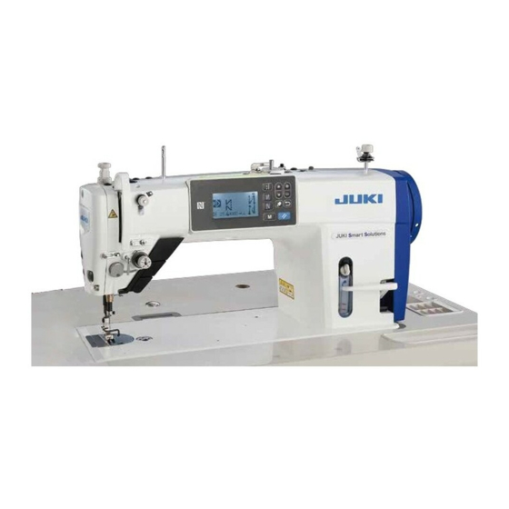
Summary of Contents for JUKI DDL-9000C-S
- Page 1 DDL-9000C-S INSTRUCTION MANUAL...
-
Page 2: Table Of Contents
CONTENTS 1. SPECIFICATIONS ......................1 1-1. Specifications of the sewing machine head ..............1 1-2. Specifications of the control box ..................1 2. SET UP ..........................2 2-1. Drawing of table ........................2 2-2. Cautions when setting up the sewing machine ..............3 2-2-1. - Page 3 3-12-2. How to confirm the amount of oil (oil splashes) ..............24 3-12-3. Sample showing the appropriate amount of oil ..............24 3-13. Adjusting the thread take-up spring and the thread take-up stroke......25 3-14. Micro-lifting mechanism of the presser foot ..............26 4.
- Page 4 7-4-1. Checking the standard adjustment ..................74 7-4-2. Standard adjustment ....................... 74 7-4-3. Standard adjustment (Adjustment at the tip position) ............74 7-5. Thread tension release releasing mechanism ..............75 7-6. Grease shortage alarm ...................... 76 7-6-1. Regarding the grease shortage alarm ................... 76 7-6-2.
-
Page 5: Specifications
Needle 134 Nm65 to 110 (DP×5 #9 to 18) 134 Nm125 to 160 (DP×5 #20 to 23) Lubricating oil JUKI NEW DEFRIX OIL No. 1 or JUKI CORPORATION GENUINE OIL 7 Motor AC servo motor Horizontal feed control Electronic control... -
Page 6: Set Up
2. SET UP 2-1. Drawing of table – 2 –... -
Page 7: Cautions When Setting Up The Sewing Machine
2-2. Cautions when setting up the sewing machine Thank you very much for the purchase of JUKI Industrial Sewing Machine this time. Make sure of items 2-1 through 2-14 before operating to use this sewing machine with ease. 2-2-1. How to carry the sewing machine Carry the sewing machine while holding the machine arm with two persons as shown in the figure. -
Page 8: Installing The Thread Stand
4) Securely attach head support rod ❾ to the table until it goes no further. Be sure to mount the machine head support rod ❾ on the machine table so that its height from the table surface becomes 63 to 68 mm. For the sewing machine provided with the AK device, be sure to mount the support rod ❾... -
Page 9: Attaching The Knee Lifter Pad
2-5. Attaching the knee lifter pad Insert knee lifter pad ❶ into attaching hole ❷ and tighten it with bolt ❸. * Adjust the position of knee lifter pad ❶ to a conve- nient place. For the reference dimension, the position is 220 mm from the bottom face of table. -
Page 10: Installing The Electrical Box
2-7. Installing the electrical box Install control box ❶ on the table using four holes ❷ ❷ a in the table. Secure the control box with four bolts ❷, four plain washers ❸, four spring washers ❹ and four hexagonal nuts ❺ supplied with the control box. -
Page 11: Connecting The Power Source Cord
2-8-2. Connecting the power source cord Voltage specifications at the time of delivery from the factory are indicated on the voltage indication seal. Connect the cord in accordance with the specifications. Power indication tag Never use under the wrong voltage and phase. (For example : In the case of 200V) Rating plate •... -
Page 12: Installing The Reactor Box
2-8-3. Installing the reactor box * For the EU-type models, install the reactor box that is supplied with the sewing machine. 1) Connect the terminals of power cord ❶ of the ❸ ❷ ❹ SC-950(951) to reactor-box PCB asm. ❷ and to reactor box mounting plate ❸. -
Page 13: Connecting The Cords
2-9. Connecting the cords DANGER : 1. To prevent personal injuries caused by electric shock hazards or abrupt start of the sewing machine, carry out the work after turning OFF the power switch and a lapse of 5 minutes or more. 2. -
Page 14: Handling The Cords
2-10. Handling the cords DANGER : 1. To prevent personal injuries caused by electric shock hazards or abrupt start of the sewing machine, carry out the work after turning OFF the power switch and a lapse of 5 minutes or more. 2. -
Page 15: Adjustment Of The Pedal
2-12. Adjustment of the pedal WARNING : Turn OFF the power before starting the work so as to prevent accidents caused by abrupt start of the sewing machine. 2-12-1. Installing the connecting rod 1) Move pedal ❸ to the right or left as illustrated by the arrows so that motor control lever ❶... -
Page 16: Lubrication
2,000 sti/min or less. 2. For the oil for hook lubrication, purchase JUKI NEW DEFRIX OIL No. 1 (part number : MDFRX1600C0) or JUKI CORPORATION GENUINE OIL 7 (part number : 40102087). -
Page 17: How To Use The Operation Panel (Basic Explanation)
2-15. How to use the operation panel (Basic explanation) 2-15-1. Selection of the language (operation to be done at first) Select the language to be displayed on the operation panel when you turn ON the power to your sewing machine for the first time after the purchase. Note that, if you turn the power OFF without selecting the language, the language selection screen will be displayed every time you turn ON the power to the sew- ing machine. -
Page 18: Names And Functions Of The Panel Keys
2-15-2. Names and functions of the panel keys ❸ ❼ ❶ ❷ ❹ ❾ ❺ ❽ ❻ Switch/display Description ❶ Item selection key This key is used for changing over the screen display or for displaying the edit screen. Refer to the explanation of each screen for details. ❷... -
Page 19: Basic Operation
2-15-3. Basic operation ① Turning ON the power switch When you turn ON the power switch, the welcome screen is displayed. ② Selecting a sewing pattern The sewing screen is displayed. ・ Select a sewing pattern. "4-2. Sewing patterns" p. Refer to for details. -
Page 20: Preparation Before Sewing
3. PREPARATION BEFORE SEWING 3-1. Attaching the needle WARNING : Turn OFF the power before starting the work so as to prevent accidents caused by abrupt start of the sewing machine. Use the specified needle for the machine. Use the proper needle in accordance with the thickness of thread used and the kinds of the materials. -
Page 21: Winding The Bobbin Thread
3-3. Winding the bobbin thread 1) Insert the bobbin deep into the bobbin winder ❽ spindle ❶ until it will go no further. 2) Pass the bobbin thread pulled out from the spool rested on the right side of the thread stand fol- lowing the order as shown in the figure on the left. -
Page 22: Threading The Machine Head
3-4. Threading the machine head WARNING : Turn OFF the power before starting the work so as to prevent accidents caused by abrupt start of the sewing machine. ❶ [NB type] [0B type] ❸ ❾ ❷ (Note) ❹ (Note) Be sure to pass the thread Do not pass this thread through the section B. -
Page 23: Presser Foot Pressure
3-6. Presser foot pressure WARNING : Turn OFF the power before starting the work so as to prevent accidents caused by abrupt start of the sewing machine. 1) Loosen nut ❷. As you turn presser spring regula- tor ❶ clockwise (in direction A), the presser foot ❶... -
Page 24: Changing The Sewing Speed
3-8. Changing the sewing speed The sewing speed is displayed in section A on the panel. (Example of display : 4,000 sti/min) [How to change] 1) Display the sewing data edit screen by ❺. pressing ❺ ❶ ❷ ❻ ❶. 2) Display "S047"... -
Page 25: Led Hand Light
3-9. LED hand light WARNING : In order to protect against personal injury due to unexpected start of the sewing machine, never bring hands near the needle entry area or place foot on the pedal during the adjustment of intensity of the LED. -
Page 26: Custom Switch
3-11. Custom switch Various operations can be carried out by operating custom switch ①. * Various operations can be allocated also to one- touch type reverse feed switch ②. ① ② ❺ ❶ ❷ ❾ held pressed for six sec- 1) Keep onds. -
Page 27: Adjusting The Amount Of Oil (Oil Splashes) In The Hook
3-12. Adjusting the amount of oil (oil splashes) in the hook WARNING : Be extremely careful about the operation of the machine since the amount of oil has to be checked by turning the hook at a high speed. 3-12-1. Adjusting the amount of oil in the hook ❹... -
Page 28: How To Confirm The Amount Of Oil (Oil Splashes)
3-12-2. How to confirm the amount of oil (oil splashes) Amount of oil (oil splashes) confirmation paper Position to confirm the amount of oil (oil splashes) Hook driving shaft front bushing Hook Approx. 70 mm * Use any paper available regardless of the material. -
Page 29: Adjusting The Thread Take-Up Spring And The Thread Take-Up Stroke
3-13. Adjusting the thread take-up spring and the thread take-up stroke ❺ ❹ [DDL-9000C-SMS] [DDL-9000C-SSH] ❽ ❾ ❾ ❽ ❻ ❶ ❻ ❶ ❶ ❸ ❸ ❷ ❷ (1) Adjusting the stroke of thread take-up spring ❶ 1) Loosen setscrew ❷. 2) Turn tension post ❸... -
Page 30: Micro-Lifting Mechanism Of The Presser Foot
3-14. Micro-lifting mechanism of the presser foot WARNING : Turn OFF the power before starting the work so as to prevent accidents caused by abrupt start of the sewing machine. When sewing velvet or the like which is fluffy, slip- page of material or damage of material is reduced by ❶... -
Page 31: How To Use The Operation Panel
4. HOW TO USE THE OPERATION PANEL 4-1. Explanation of the sewing screen (when selecting a sewing pattern) On the sewing screen, the shape and set values of the currently-sewn sewing pattern are displayed. The display and button operation differ according to the selected sewing pattern. Note that the sewing screen shows two different displays, i.e., the sewing pattern display and the count- er display. - Page 32 Switch/display Description ❶ Item selection key This key is used for changing over the display of screen shown below: Pattern display / Sewing counter / Bobbin counter display * This key cannot be operated during sewing. "4-3. Counter function" p. 43 * Refer to for the description of the counter display.
- Page 33 Switch/display Description Number of stitches of Numbers of stitches of reverse feed stitching at the end of sewing C and D reverse feed stitching are displayed. (0 to 99 stitches) (at end) C, D * These numbers of stitches are only displayed in the case the reverse feed stitching is performed at the end of sewing.
-
Page 34: Sewing Patterns
4-2. Sewing patterns Patterns which are frequently sewn can be registered as sewing patterns. Once the patterns are registered as sewing patterns, the desired sewing pattern can be called up only by selecting its sewing pattern number. As many as 99 different patterns can be registered as sewing patterns. 4-2-1. -
Page 35: Reverse Feed Stitching (At Start) Pattern
4-2-2. Reverse feed stitching (at start) pattern A stitch shape of the reverse feed stitching (at start) is set by following the steps of procedure described below. (1) Enabling the reverse feed stitching (at start) pattern ❸ In the state pictograph A is displayed on the screen, the reverse feed stitching (at start) is enabled. - Page 36 ③ Applying the changed item ❷ After the change in the numeric value, ❻ press to return the screen to the sewing screen. The data B you have changed is dis- played. ❻ <Sewing screen> "Type of stitch" and "edit item" that can be selected are as follows: ❷...
-
Page 37: Editing The Sewing Patterns
4-2-3. Editing the sewing patterns (1) Edit method (in the case free stitching, constant-dimension sewing or multi-layer stitching is selected) "8-1. Setting up the polygonal-shape * In the case polygonal-shape stitching is selected, refer to stitching" p. ① Displaying the sewing pattern edit screen On the sewing screen which is displayed in the case free stitching, constant-di- mension sewing or multi-layer stitching... - Page 38 * In the case the constant-dimension sewing pattern is selected, the teach- ing screen is displayed by pressing ❺ during setting of the number of stitches. (Only in the case the number of stitches can be changed.) Refer to "4-2-6. Teaching function" p. for the teaching function.
-
Page 39: List Of Pattern Functions
4-2-4. List of pattern functions (1) Setting items under the pattern sewing mode Data Item name Input range S001 Shape Free Constant dimension Multi-layered Polygonal shape S002 Number of stitches/ ― 1 to 2000 1 to 15 ― Number of times S003 Pitch -5.00 to 5.00 / Custom pitch No.1 to 20 ―... - Page 40 Data Item name Input range S066 Feed locus ― S068 Part number - 24 characters *2 S069 Process - 24 characters S070 Comment 50 characters *1 : This is the one-touch type changeover function. Refer to "4-2-7. One-touch type changeover button" p. *2 : Only the limited number of characters is displayed.
-
Page 41: Reverse Feed Stitching (At End) Pattern
4-2-5. Reverse feed stitching (at end) pattern A stitch shape of reverse feed stitching (at end) is set by following the steps of procedure described below. (1) Enabling the reverse feed stitching (at end) pattern When pictograph A is displayed on the screen, reverse feed stitching (at end) is enabled. -
Page 42: Teaching Function
4-2-6. Teaching function This is the function that enables entry of the number of stitches of a sewing pattern using the actual number of stitches sewn. This function screen can be displayed from the sewing pattern edit screen. * The teaching function can be used in the case the "constant-dimension sewing" or "polygonal-shape stitching"... - Page 43 ③ Confirming the data entered under the teaching mode Confirm the data entered under the teach- ❻ . ing mode with Then, the screen returns to the sewing pattern edit screen. ❻ <Sewing pattern edit screen> (2) How to set (polygonal-shape stitching) ①...
-
Page 44: One-Touch Type Changeover Button
③ Confirming the data entered under the teaching mode Confirm the data entered under the teach- ❻ . ing mode with Then, the screen returns to the sewing pattern edit screen. ❻ <Sewing pattern edit screen> 4-2-7. One-touch type changeover button In the case the one-touch function is assigned to the custom switch, the pitch, sewing speed and feed dog height can be changed over by pressing the custom switch. -
Page 45: Registration Of A New Sewing Pattern
4-2-8. Registration of a new sewing pattern A newly-created sewing pattern is registered by following the steps of procedure described below. ① Selecting the new-pattern creating function ❶ 1. Select the sewing pattern management ❾ . Then, screen by pressing ❺... -
Page 46: Copying A Pattern
4-2-9. Copying a pattern ❾ . 1. Press ❾ ❺ ❶ 2. Select "04 Sewing management" by ❶ . Press ❺ . pressing ❺ ❶ 3. Select "01 Pattern copy" by pressing ❶ . Press ❺ . ❺ ❶ ❷ 4. -
Page 47: Counter Function
4-3. Counter function This function counts sewing in the predetermined unit and gives a visible alarm on the screen when the preset value is reached. 4-3-1. Displaying the sewing screen under the counter display mode ❶ ❷ Current value on the counter ❶... -
Page 48: How To Set The Counter
4-3-3. How to set the counter ① Selecting the counter setting ❶ 1. Display the mode screen by pressing ❾ . 2. Select the "02 Counter setting" with ❶ , and press ❺ . ❾ ❺ <Mode screen> ❶ 1. Select the type of counter for setting ❶... - Page 49 Bobbin thread counter UP counter (adding method): The bobbin thread counter adds one to its current value every time the sewing machine sews 10 stitches. When the current value reaches the preset value, the count-completion screen is displayed. DOWN counter (subtracting method): The bobbin thread counter subtracts one from its current value every time the sewing machine sews 10 stitches.
-
Page 50: How To Reset The Count-Completion State
4-3-4. How to reset the count-completion state When the predetermined conditions are satisfied during sewing, the count-comple- tion screen is displayed. The counter is reset by pressing ❽ . Then, the mode is returned to the sewing mode. In this mode, the counter starts counting again. -
Page 51: Simplified Chart Of Panel Displays
4-4. Simplified chart of panel displays – 47 –... -
Page 52: List Of Memory Switch Data
4-5. List of memory switch data Item Setting range Unit U001 Soft-start function 0 to 9 Stitch The initial value differs with the machine head. (0: OFF) ー U007 Bobbin thread count-down unit 0 to 2 0: 10 stitches / 1: 15 stitches / 2: 20 stitches U008 Reverse feed stitching speed 150 to 3000 sti/min... - Page 53 Item Setting range Unit ー U047 Presser-foot lift finishing position -1000 to -100 The position to which the presser foot goes up when the back part of the pedal is depressed to its first step (1st-step spring position) U049 Presser foot lowering time 0 to 500 The initial value differs with the machine head.
- Page 54 Item Setting range Unit U120 Main shaft reference angle correction -60 to 60 Degree The main shaft reference signal angle (0 degree) is corrected with the value set using this memory switch. U121 Upper stop position angle correction -15 to 15 Degree The position at which the sewing machine stops with its needle down is corrected.
- Page 55 Item Setting range Unit ー U401 Input unit of pitch 0 to 2 0: Pitch (mm) / 1: Number of stitches per inch 2: Number of stitches in 3 cm U402 Automatic lock time 0 to 300 Second The sewing machine is automatically locked in the case the operation panel is not operated for a predetermined period of time.
-
Page 56: List Of Errors
4-6. List of errors Error Description of error Cause Item to be checked code E000 Execution of data • In the case the machine head is initialization (This is changed. not an error.) • In the case the initialization operation is executed. - Page 57 Error Description of error Cause Item to be checked code E302 Head-tilt detection • In the case the Tilt detection switch • Check whether the machine head error is turned ON when the power to the is tilted before turning OFF the (When the safety sewing machine remains ON.
- Page 58 Error Description of error Cause Item to be checked code E903 85-V power supply • In the case the 85-V voltage is not • Check whether the motor is faulty fault properly output. • Check the F2 fuse. E904 24-V power supply •...
-
Page 59: Memory Switch Data
4-7. Memory switch data The memory switch data is the sewing machine operation data which commonly affects all sewing pat- terns and cycle patterns. 4-7-1. Setting up the memory switch data ① Selecting the category of the memory switch data. ❶... - Page 60 ③ Confirming the data entered ❻ to confirm the data and 1. Press return the current screen to the memo- ry switch category selection screen. ❻ again to return the cur- Press rent screen to the mode screen. ❻ yet again to return the Press current screen to the sewing screen.
-
Page 61: Main New Functions
5. MAIN NEW FUNCTIONS "4-2. As a result of computerization of the feed mechanism, various adjustments can be carried out. Refer to Sewing patterns" p. 30 for details. Due to computerization of the feed mechanism, the machine generates noise that is specific to the stepping motor when it runs at a low speed. - Page 62 ❺ ❶ ❷ ❻ ❶. 3) Select "U057" by pressing ❺. Press 4) Select the feed dog status during thread trimming (0 : Feed dog DOWN, 1 : Feed ❷. dog UP) by pressing ❻. 5) Confirm your entry by pressing Then, the sewing screen is displayed.
- Page 63 [How to adjust condensation pitch] In the case of carrying out shorter-thread remaining thread trimming (when condensation is placed in Sewing pitch ON), set values of the condensation pitch and the number of stitches are adjustable. Adjust those set values appropriately according to the item to be sewn.
-
Page 64: Adjusting The Feed Dog Height
5-2. Adjusting the feed dog height 1. Be aware that interference between the throat plate and feed dog can occur depending on the gauge used. Be sure to check the clearance in the gauge to be used. (The clearance must be 0.5 mm or more.) 2. -
Page 65: Operating Timing Of The Feed
5-3. Operating timing of the feed When you have changed the stitch length, feed dog height or feed timing, run the sewing machine at a low speed to make sure that the gauge does not interfere with the changed part. Timing between the needle and feed can be adjusted on the operation panel. -
Page 66: Changing The Feed Locus
5-4. Changing the feed locus The feed locus can be changed according to the item to be sewn. [How to change] 1) Display the sewing data edit screen by ❺. pressing ❺ ❶ ❷ ❻ ❶. 2) Display "S048" by pressing 3) Change the feed locus by pressing ❷. -
Page 67: Care
6. CARE Perform the maintenance below every day for longer use of your machine. 6-1. Maintenance mode Use this mode for the maintenance of the sewing machine such as adjustment of the hook timing and re- placement of the gauge. While the sewing machine is placed in the maintenance mode, it will not start even if the pedal is depressed. -
Page 68: Cleaning
❶ 3. Be aware that grease can leak from the thread take-up cover and needle bar if the amount of grease is excessive. 4. Be sure to use JUKI GREASE A TUBE ❶ (part number : 40006323). – 64 –... -
Page 69: Applying Grease To The Needle Bar Lower Bushing And The Presser Bar Bushing
6-5. Applying grease to the needle bar lower bushing and the presser bar bushing WARNING : Turn OFF the power before starting the work so as to prevent accidents caused by abrupt start of the sewing machine. Carry out greasing with the needle bar installed. -
Page 70: Adjustment Of The Machine Head (Application)
7. ADJUSTMENT OF THE MACHINE HEAD (APPLICATION) 7-1. Needle-to-hook relationship WARNING : Turn OFF the power before starting the work so as to prevent accidents caused by abrupt start of the sewing machine. Adjust the timing between the needle and the hook as follows : 1) Adjusting the needle bar height. -
Page 71: Adjusting The Needle Thread Presser Device
7-2. Adjusting the needle thread presser device WARNING : Turn OFF the power before starting the work so as to prevent accidents caused by abrupt start of the sewing machine. The needle thread presser device is able to tuck the needle thread on the wrong side of material as in the case of the conventional wiper device. - Page 72 [Adjusting the remaining length of needle thread] Adjust the length of needle thread remaining at the needle to 35 to 45 mm (for both the S and H types) by turning thread tension No. 1 nut ②. 1) Turn thread tension No. 1 nut ② clockwise (in di- rection A), to shorten the thread length remaining on the needle after thread trimming or counter- ②...
- Page 73 [Response to problems occurring at the beginning of sewing] • In the case needle thread breakage occurs when using a thin thread or fragile thread • In the case needle thread is not tucked on the wrong side of material •...
-
Page 74: Adjusting The Thread Trimmer
7-3. Adjusting the thread trimmer WARNING : Turn OFF the power before starting the work so as to prevent accidents caused by abrupt start of the sewing machine. 7-3-1. For checking of the thread trimming cam ❻ B´ timing The purpose of the adjustment of the thread trim- ming cam is to align marker line A on pulley cover ❺... -
Page 75: Checking Of The Knife Unit
7-3-3. Checking of the knife unit WARNING : Turn OFF the power before starting the work so as to prevent accidents caused by abrupt start of the sewing machine. 1) Check to make sure that the power switch is in ❶... -
Page 76: Adjustment Of The Knife Unit
7-3-4. Adjustment of the knife unit WARNING : Turn OFF the power before starting the work so as to prevent accidents caused by abrupt start of the sewing machine. 1) Check to make sure that the power switch is in the OFF state. -
Page 77: Adjustment Of Thread Trimming Speed
7-3-5. Adjustment of thread trimming speed The thread trimming speed has been adjusted to 300 sti/min (H type : 220 sti/min) at the time of shipment. This means that the high-speed thread trimming has been selected. Depending on the type of thread to be used, the thread trimming speed should be increased. On the other hand, in the case of using fragile thread (such as a high-count filament type thread or cotton thread), the thread trimming speed should be decreased to reduce damage to the thread. -
Page 78: Adjustment Of The Picker
7-4. Adjustment of the picker WARNING : Turn OFF the power before starting the work so as to prevent accidents caused by abrupt start of the sewing machine. In the standard adjustment state of the picker, the center of picker ❻ is almost aligned with the center of U-shape section of... -
Page 79: Thread Tension Release Releasing Mechanism
7-5. Thread tension release releasing mechanism WARNING : Turn OFF the power before starting the work so as to prevent accidents caused by abrupt start of the sewing machine. By means of the thread tension release releas- ing mechanism, sewing can be performed without ❷... -
Page 80: Grease Shortage Alarm
7-6. Grease shortage alarm 7-6-1. Regarding the grease shortage alarm When the time of maintenance of grease approaches, the error message "E220 Warning against shortage of grease" is displayed. ❽. In This error is reset by pressing this state, the sewing machine can be con- tinuously used for a certain period of time. -
Page 81: Regarding K118 Error Resetting Procedure
7-6-3. Regarding K118 error resetting procedure ❾ held pressed for six sec- 1) Keep onds. ❾ ❺ ❶ 2) Select "01 Memory switch" by pressing ❶. Press ❺. ❺ ❶ 3) Select "01 Display all" by pressing ❶. Press ❺. ❺... -
Page 82: How To Use The Operation Panel (Application)
8. HOW TO USE THE OPERATION PANEL (APPLICATION) 8-1. Setting up the polygonal-shape stitching <Example of pattern> A polygonal-shape stitching pattern consists of Step 5 20 steps (at the maximum) of constant-dimen- sion sewing patterns. Specific sewing conditions can be set on a step-by-step basis. Step 1 Step 4 Step 2... - Page 83 ・ A step is added after the currently-selected step by pressing "+", or before the currently-selected ❷ . step by pressing "−" of ❶ while the leading step is being ・ A step is added at the end of steps by pressing "▼" of selected.
-
Page 84: Cycle Pattern
8-2. Cycle pattern It is possible to combine several different sewing ・・・ patterns as one cycle pattern for sewing. As many as 10 patterns can be input in one cycle Step Step Steps 1 to 10 can be registered pattern. This function is helpful in the case several different patterns are regularly repeated in a prod- uct sewing process. -
Page 85: Creating A New Cycle Pattern
8-2-2. Creating a new cycle pattern ① Selecting the new cycle pattern creating function ❶ ❾ on the sewing screen 1. Press to display the mode screen. 2. Select "04 Cycle management" by ❶ Then, press pressing ❺ to display the cycle pattern man- agement screen. -
Page 86: Editing The Cycle Patterns
8-2-3. Editing the cycle patterns ① Displaying the cycle pattern edit screen The cycle pattern edit screen is displayed ❺ on the sewing screen by pressing which appears when the cycle pattern is selected. ❺ <Sewing screen(Cycle pattern)> ② Editing the comment for a cycle pattern ❶... - Page 87 ③ Editing cycle pattern steps ❶ ❷ ❶ . 1. Select a step by pressing 2. Pattern number of a step can be ❷ while changed by pressing the step is being selected. ❺ ❽ ❻ <Cycle pattern edit screen> ❻...
-
Page 88: Copying A Pattern
8-3. Copying a pattern The selected pattern (sewing pattern and cycle pattern) can be copied to any other pattern of the speci- fied number. The existing pattern cannot be overwritten. Delete it first and copy the selected pattern. 8-3-1. Copying a sewing pattern ①... -
Page 89: Copying A Cycle Pattern
8-3-2. Copying a cycle pattern ① Selecting the cycle pattern copy function ❶ ❾ on the sewing screen 1. Press to display the mode screen. 2. Select "04 Cycle management" by ❶ . Then, press pressing ❺ to display the cycle pattern management screen. -
Page 90: Deleting A Pattern
8-4. Deleting a pattern 8-4-1. Deleting a sewing pattern ❶ ❷ 1. Display the sewing pattern copy/dele- tion screen referring to "8-3-1. Copy- ing a sewing pattern" p.84. 2. Select a sewing pattern No. to delete ❶ . Select the by pressing ❷... -
Page 91: Custom Pitch
8-5. Custom pitch It is possible to register as many as 20 different sewing Step1 designs each of which consists of several different pitches 1 mm 3 stitches (10 steps at the maximum). As many as 100 stitches of the same pitch can be set in Step2 one step. -
Page 92: Creating A New Custom Pitch
8-5-2. Creating a new custom pitch Create the new custom pitch No. 1 shown in <Fig. 1> as an example. ① Selecting the new custom pitch creating function ❶ ❾ on the sewing screen 1. Press to display the mode screen. 2. - Page 93 ❷ 1) In the case of setting the number of stitches The number of stitches can be input in the range from 0 to 100. Set the number of stitches A for step 1 ❷ . to 3 by pressing 2) In the case of setting the pitch The pitch can be input in the range ❷...
-
Page 94: Custom Pitch Edit Function
④ Confirming the numeric value ❻ to confirm the data and Press return the current screen to the Custom pitch management screen. ❻ again to return the current Press screen to the mode screen. ❻ yet again to return the cur- Press rent screen to the sewing screen. -
Page 95: Copying/Deleting A Custom Pitch
8-5-4. Copying/deleting a custom pitch (1) Copying a custom pitch ① Selecting the custom pitch copy function ❶ 1. Display the custom pitch management screen referring to "8-5-2. Creating a new custom pitch" p.88. 2. Select "02 Copy/delete a CP" by press- ❶... - Page 96 (2) Deleting a custom pitch ❶ ❷ 1. Display the custom pitch copy/deletion screen referring to "8-5-4.(1) Copying a custom pitch" p.91. 2. Select a custom pitch No. to delete by ❶ . Select the trash pressing ❷ . by pressing ❺...
-
Page 97: Condensation Custom Pattern
8-6. Condensation custom pattern Condensation stitches can be sewn while specifying needle entry points as desired, by setting a conden- sation custom. Step1 As many as 20 steps can be created in one conden- 1 mm 3 stitches sation custom pattern. For each step, as many as nine different patterns of start and end of sewing can be registered. -
Page 98: Creating A New Condensation Custom
8-6-2. Creating a new condensation custom Create the new condensation custom No. 1 shown in <Fig. 1> as an example. ① Selecting the new condensation custom creating function ❶ ❾ on the sewing screen 1. Press to display the mode screen. 2. - Page 99 ❷ 1) In the case of setting the number of stitches The number of stitches can be input in the range from 1 to 100. Set the number of stitches A for step 1 ❷ . to 3 by pressing 2) In the case of setting the pitch The pitch can be input in the range ❷...
-
Page 100: Condensation Custom Edit Function
④ Confirming the numeric value ❻ to confirm the data and Press return the current screen to the new con- densation custom creation screen. ❻ again to return the current Press screen to the condensation custom man- agement screen. ❻ yet again to return the cur- Press ❻... -
Page 101: Copying/Deleting A Condensation Custom
8-6-4. Copying/deleting a condensation custom (1) Copying a condensation custom ① Selecting the condensation custom copy function ❶ 1. Display the condensation custom management screen referring to "8- 6-2. Creating a new condensation custom" p.94. 2. Select "02 Copy/delete a CC" by ❶... - Page 102 (2) Deleting a condensation custom ❶ ❷ 1. Display the condensation custom copy/ deletion screen referring to "8-6-4.(1) Copying a condensation custom" p.97. 2. Select a condensation custom No. to ❶ . Select delete by pressing ❷ . the trash by pressing ❺...
-
Page 103: Information
8-7. Information 8-7-1. Simple lock Once the simple lock is enabled, key operation can be disabled if no operation is carried out on the sewing screen for a certain period of time, thereby preventing maloperation. The status of the simple lock can be changed over between enable/disable by ❽... -
Page 104: Communication Function
8-7-2. Communication function Data can be input/output by means of a USB thumb drive. (1) How to use the communication function ① Selecting the communication function ❶ ❾ on the sewing screen 1. Press to display the mode screen. 2. Select "09 Communication" by press- ❶... - Page 105 Custom pitch data VD00XXX.VDT It is the data of needle entry point created with (XXX:001~999) PM-1, and the data format that can be operated in common between JUKI sewing machines. Condensation VD00XXX.VDT It is the data of needle entry point created with...
-
Page 106: How To Set Up The Functions
8-8. How to set up the functions 8-8-1. How to change over to the function setting mode (1) Setting the optional input/output ① Selecting the optional input/output setting function ❷ ❾ held pressed for six 1. Keep seconds on the sewing screen to dis- play the mode screen. -
Page 107: List Of Function Settings
8-8-2. List of function settings (1) List of input functions Abbreviation Function item No function Needle up/down correction stitching Reverse-feed correction stitching Function for cancelling reverse-feed stitching (at end) once Thread trimmer function Presser lifter function 1-stitch correction stitching SEBT Function for cancelling reverse-feed stitching (at start) (at end) LINH Function for prohibiting depress on the front part of pedal... -
Page 108: Details Of Each Selection Function
8-8-3. Details of each selection function Various functions can be selected on the mode screen. (1) Checking the version information ① Displaying the version information ❶ ❾ on the sewing screen 1. Press to display the mode screen. 2. Select "07 Version" by pressing ❶... - Page 109 (3) Setting the key-lock and the password Specific key operation can be prohibited to disable change in data by enabling the key-lock. Furthermore, change in the status of the key-lock between enable/disable can be prohibited by setting a four-digit password. ①...
- Page 110 ③ Setting the key-lock ❶ 1. Select "02 Fnction-limit change" by ❶ on the function pressing restriction setting management screen. ❺ to display the key- Then, press lock setting screen. ❺ to display the key-lock 2. Press item setting screen. ❺...
- Page 111 * In the case the password has been set up and the key-lock has been enabled, the password input screen is displayed when the mode key is pressed on the sewing screen. (Refer to the description given below for the operation procedure.) Once the correct password is input, input of the password is not required until the power is turned OFF.
-
Page 112: External Interface
• Never forcefully insert a USB thumb drive into the USB connector while carefully checking the ori- entation of the USB thumb drive. Forceful insertion of the USB thumb drive can cause failure. • JUKI does not compensate for loss of data stored on the USB device caused by using it with this sewing machine. -
Page 113: Nfc
(such as tablet and smartphone) on which JUKI application for Android [JUKI Smart App] has been installed, by means of the NFC communication function. Refer to the Instruction Manual for JUKI Smart App for details of JUKI application for Android [JUKI Smart App].
Need help?
Do you have a question about the DDL-9000C-S and is the answer not in the manual?
Questions and answers