
Related Manuals for JUKI DDL-9000A


Summary of Contents for JUKI DDL-9000A
- Page 1 ® Direct-drive, High-speed, 1-needle, Lockstitch Machine with Automatic Thread Trimmer DDL-9000A ENGINEER’S MANUAL 40059361 No.E379-00...
- Page 2 PREFACE This Engineer’s Manual is written for the technical personnel who are responsible for the service and maintenance of the machine. The Instruction Manual for these machines intended for the maintenance personnel and operators at an apparel factory contains operating instructions in detail. It is advisable to use the Instruction Manual and Parts List for SC-810 and SC-910N together with this Engineer's Manual when carrying out the maintenance of these machines.
-
Page 3: Table Of Contents
CONTENTS 1. Specifications ....................2. Name of each component ................2 3. Standard adjustment ..................4 (1) Feed dog height and gradient ................... 4 (2) Timing for the needle and the inner hook ..............6 (3) Needle and feed timing ....................8 (4) Feed locus and phase .................... -
Page 4: Screws For Attachment And Positions Of External Parts
3. Method of standard adjustments (Adjustment of tip position) ............61 10) Adjustment of the drive arm stopper ....................62 11) Replacement of the knife unit ......................64 (12) Adjustment of the wiper (DDL-9000A- -WB/OB) ..........66 (13) Adjustment of feed lever pressure ................68 (14) Adjustment of external parts ................... -
Page 5: Specifications
*2: JUKI New Defrix Oil No. 1 or JUKI Machine Oil No. 7 (equivalent to ISO VG7) *3: JUKI New Defrix Oil No.2 (equivalent to ISO VG32) *4: When a version of the DDL-9000A-MA specification is used over a speed of 4,000rpm, the presser pressure adjusting spring should be replaced for the standard type. -
Page 6: Name Of Each Component
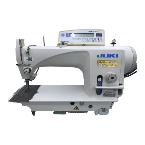
2. Name of each component Power switch Knee lifter Operation panel (CP-170 or IP-110) Oil filler port (except for DDL-9000A-DS) Pulley cover Feed lever Thread stand Minute adjustable presser lifting screw Control box (SC-810 or SC-910N) Hand wheel Operation pedal... - Page 7 This dial adjusts the front feeding amount. Knee lifter Oil filler port (except for DDL-9000A-DS) This port is used for lubrication to the hook. (except for DDL-9000A-DS) Feed lever This lever allows users to conduct reverse stitching. Minute adjustable presser lifting screw...
-
Page 8: Standard Adjustment
9000A- S, 9000A- A : 0.8mm 9000A-SH : 1.2mm Standard feed dog height (Feed dial graduation 0) 0.8mm : DDL-9000A- S, DDL-9000A- A 1.2mm : DDL-9000A-SH Standard feed dog gradient The engraved marker dot on the feed bar shaft is adjusted by a feed dog of relevant standard. - Page 9 If the height has to be increased for an unavoidable reason, the amount of return can be reduced by adjusting the gradient of the feed dog to raise its tip. 0.8mm DDL-9000A- 1.2mm DDL-9000A-SH – 5 –...
-
Page 10: Timing For The Needle And The Inner Hook
(2) Timing for the needle and the inner hook Standard Adjustment 0.04 to 0.1mm Lubricated hook K Part No. : 23621303 – 6 –... - Page 11 2. Too much clearance may give rise to stitch skipping. <Information about the dry hook> A dry hook (RP hook) is employed for the DDL-9000A-DS type. For replacement, use the part numbers specified below. The hook part numbers come in two types according to the specifications.
-
Page 12: Needle And Feed Timing
(engraved marker line position) Other than A-SH A-SH Needle and feed timing Standard Adjustment Models Other than DDL-9000A-SH DDL-9000A-SH Vertical feed cam engraved marker line 0° +10° Feed dial graduations In a moment when the feed dog is positioned below the upper... - Page 13 * In cases other than the DDL-9000A-SH, coincidence of the engraved marker dot of the pulley cover with the engraved...
-
Page 14: Feed Locus And Phase
(4) Feed locus and phase Standard Adjustment 3. Timing slow 1. Timing standard 2. Timing fast – 10 –... - Page 15 Adjustment Procedure Results of Improper Adjustment [Feed locus change] o When tightening the two setscrews By adjusting the phase of the vertical feed cam , it is possible to change of the vertical feed cam , this the up/down timing for the feed locus and needle. work should be done while a good Adjustments can be carried out with two setscrews centering is secured.
-
Page 16: Bobbin Insertion
(5) Bobbin insertion Standard Adjustment 1) Bobbin case with idling prevention spring (Drawing is for 11038700.) o For the bobbin case with idling prevention spring Bobbin revolution – 12 –... - Page 17 (Made of aluminum) 1) Bobbin case with idling prevention spring The DDL-9000A Series employs the bobbin case with an idling prevention spring. Adjustments of idling prevention spring tension can be carried out in the procedures below. If bobbin idling occurs, increase the idling prevention spring tension When the bobbin runs idle Increase the tension of the idle-prevention spring.
-
Page 18: Adjustment Of Inner Hook Presser Position
(6) Adjustment of inner hook presser position Standard Adjustment Inner hook Needle entry * As seen from above, after removing the throat plate About the standard part numbers Other than DDL-9000A-SH DDL-9000A-SH Inner hook presser 40032052 40037405 – 14 –... - Page 19 Adjustment Procedure Results of Improper Adjustment 1. The front and rear positions of the inner hook presser can be adjusted by means of the setscrew [Standard adjusting value] o If the embossed part of the inner Fasten the needle entry section by means of the setscrew hook presser has any flaw, this that it is located closer to the shoulder section toward the front side...
-
Page 20: Lubrication
(7) Lubrication Standard Adjustment 1) Method of lubrication DDL-9000A-S (Specification for minute-quantity lubrication) Float DDL-9000A-M (Specification for semi-dry items) Float DDL-9000A-DS (Specification for dry items) – 16 –... - Page 21 Quantity of oil can be adjusted by the hook oil adjusting screw Lubricant can be fed to the oil tank through the arm lubrication hole 3. DDL-9000A-DS (Specification for dry items) Face plate needle bar lubrication : Lubrication by grease sealed in the needle bar lower metal Hook : Dry hook (RP hook) –...
-
Page 22: Method Of Lubrication To The Oil Tank
(7) Lubrication Standard Adjustment 2) Method of lubrication to the oil tank (DDL-9000A-S and DDL-9000A-M only) 3) Method of oil drainage from the oil tank (DDL-9000A-S and DDL-9000A-M only) Engraved marker line MAX Engraved marker line MIN – 18 –... - Page 23 1. Remove the lubrication hole cap and replenish the JUKI New Defrex Oil No. 1 (Part No.: MDFRX160000) or the JUKI Machine Oil No. 7 (Part No.: MML007600CA) with the use of an accessory oilcan. 2. Feed the oil until the tip of the oil level indicator bar...
-
Page 24: Cleaning Of The Oil Filter
(7) Lubrication Standard Adjustment 4) Cleaning of the oil filter (DDL-9000A-S and DDL-9000A-M only) – 20 –... - Page 25 3. Remove the lubrication pipe from the float case 4. Remove thread chips and material dust accumulated in the oil filter Refer to [4. Maintenance – (3) Configuration and adjustment of the lubrication mechanism (DDL-9000A-SS, SH, MA, MS)]. – 21 –...
-
Page 26: Oil In The Gear Box
(7) Lubrication Standard Adjustment 5) Oil in the gear box 6) Placement/displacement of the gear box cover 7) Cautions for gear box cover oil during transportation Adequate oil level line (top) Oil level Adequate oil level line (bottom) – 22 –... - Page 27 140cc of the JUKI New Defrex Oil No. 2. (JUKI New Defrex Oil No. 2 Part No.: MDFRX2700C0) * After replenishment, confirm the oil level through the oil peep window * Apply a sealant when mounting the lubrication stop plug again.
-
Page 28: Adjustment Of Hook Oil Quantity
Oil quantity (large) Oil sprinkles from the hook Oil sprinkles from the hook • DDL-9000A-SS, A-M : 1 to 1.5mm • DDL-9000A-SS, A-M : 0.5 to 1mm • DDL-9000A-SH : 2 to 4mm • DDL-9000A-SH : 1 to 3mm – 24 –... - Page 29 Adjustment Procedure Results of Improper Adjustment 8) Adjustment of hook oil quantity When the hook oil quantity adjusting screw is tightened (turned to the right), the amount of hook oil is increased. When it is loosened (turned to the left), the amount of hook oil is decreased. 9) Hook oil adjustment procedures o By feeding very much oil, let the 1.
-
Page 30: Adjustment Of The Amount Of Feeding
(8) Adjustment of the amount of feeding Standard Adjustment 1) Adjustment of forward feed stitch length 2) Adjustment of reverse feed stitch length (manual) 3) Adjustment of reverse feed stitch length (motor-power) – 26 –... - Page 31 Adjustment Procedure Results of Improper Adjustment * Figures on the graduations are indicated in the unit of mm. 1) Adjustment of forward feed stitch length 1. Turn the feed adjust dial in the direction of the arrow so that the required figure is adjusted to the engraved marker dot of the arm.
-
Page 32: Optional Switch
(8) Adjustment of the amount of feeding Standard Adjustment 4) Optional switch – 28 –... - Page 33 Adjustment Procedure Results of Improper Adjustment 4) Optional switch When an optional switch is used, the functions specified below become available by a one-touch action. (SC-910N) (Cautions) Select one of the functions specified below by taking a one-touch action. Optional switch part No.: 23632656 1.
-
Page 34: Adjustment Of Normal/Reverse Stitching
(8) Adjustment of the amount of feeding Standard Adjustment 5) Adjustment of normal/reverse stitching 6) Adjustment of Feed 0 1. Method by removing the gear box cover (standard adjustment) M4 hexagon wrench – 30 –... - Page 35 Adjustment Procedure Results of Improper Adjustment 5) Adjustment of normal/reverse stitching 1. Pinch a piece of paper beneath the presser hardware and set the feed dial graduation at 3. 2. Let the sewing machine fall down. o Adjust the direction of the en- 3.
-
Page 36: Method Without Removing The Gear Box Cover (Fine Adjustment)
(8) Adjustment of the amount of feeding Standard Adjustment 6) Adjustment of Feed 0 2. Method without removing the gear box cover (fine adjustment) Screwdriver M4 hexagon wrench – 32 –... - Page 37 Adjustment Procedure Results of Improper Adjustment 2. Method without removing the gear box cover (fine adjustment) * This adjusting method is intended for fine adjustments based on the above-mentioned standard adjustments. Even though the gear box cover is left mounted, the Feed 0 position can still be adjusted.
-
Page 38: Adjustment Of The Feed Dial Section
(8) Adjustment of the amount of feeding Standard Adjustment 7) Adjustment of the feed dial section Part Configuration Diagram of the feed dial mechanism Application of appropriate grease Insertion of the arm in temporarily joined condition Arm’s engraved marker dot Feed dial 0 Adjustments with the use of minus-screwdriver tip Split section of the feed adjust screw... - Page 39 . Then, make a temporary joint. Information about the appropriate grease Part name Part No. JUKI grease A 40006323 2. In the state of temporary joint, enter the part to the inner part of arm’s feed dial section. 3. Tighten the feed control base...
-
Page 40: Adjustment Of The Reverse Feed Solenoid
(8) Adjustment of the amount of feeding Standard Adjustment 8) Adjustment of the reverse feed solenoid 9) Adjustment of feed changing shaft balancer arm (asm) positioning Engraved marker dot Engraved marker line – 36 –... - Page 41 Adjustment Procedure Results of Improper Adjustment 8) Adjustment of the reverse feed solenoid The amount of reverse feeding is limited to 4mm at the time of shipment. If usage exceeds the limitation of 4mm, readjust the position of the reverse feed solenoid [Adjustment of reverse feed solenoid positioning] 1.
-
Page 42: Adjustment Of The Presser Lifter
(9) Adjustment of the presser lifter Standard Adjustment 1) Adjustment of the presser pressure Height of the presser adjusting screw be read from the upper face value of the nut Example: Approx. 40mm 2) Adjustment of thread release changeover Upward Downward –... - Page 43 * Standard value of the presser adjusting screw height Presser Presser Specifications Height mm pressure N pressure kg DDL-9000A- DDL-9000A-SH DDL-9000A-MA 2) Adjustment of thread release changeover o Adequate thread tension can be 1. When thread release changeover is adjusted, thread tension disc maintained even when the knee floating can be cleared.
-
Page 44: Adjustment Of The Micro-Lifter
(9) Adjustment of the presser lifter Standard Adjustment 3) Adjustment of the micro-lifter Approx. 9mm 4) Adjustment of the micro-lifter unit (available separately) 22908552 Presser lifter cam (using the head connector) B1521555000 Presser lifter lever setscrew (using the head connector) Components of the micro-lifter unit Part No. - Page 45 : 9mm 4) Adjustment of the micro-lifter unit (available separately) o No tools are required. Standard DDL-9000A is equipped with a micro-lifter unit. If frequent Fine adjustments can be carried adjustments are anticipated, however, it is recommended to use out in a sitting posture.
-
Page 46: Adjustment Of Needle Stop Position
(10) Adjustment of needle stop position Standard Adjustment 1) Adjustment of upper stop position (Stop position after thread trimming) 2) Adjustment of lower stop position Setup No. Functions Standard Setting range Upper needle stop position –15 to 15 Lower needle stop position –15 to 15 –... - Page 47 Adjustment Procedure Results of Improper Adjustment 1) Adjustment of upper stop position (Stop position after thread trimming) The standard needle stop position is located where the engraved marker dot A of the pulley cover coincides with the white marker dot B of the hand wheel.
-
Page 48: Thread Trimming Unit
(11) Thread trimming unit Standard Adjustment 1) Standard timing for the thread trimming cam Operator side Turn the thread trimming cam hand in this direction. Drawing as seen from A (left side) – 44 –... -
Page 49: Method Of Confirmation
Adjustment Procedure Results of Improper Adjustment Arm’s engraved marker dot coincides with hand wheel’s engraved marker dot (red) or colorless Standard thread trimming timing for each specification Hand wheel’s engraved Arm’s engraved Specification marker dot marker dot Red color Other than 9000A-SH Colorless 9000A-SH 1. -
Page 50: Correct Position Of The Moving Knife
(11) Thread trimming unit Standard Adjustment 2) Correct position of the moving knife Extreme backward position Needle core Needle core 9000A-SS, A-DS, A-M 9000A-SH Information about the initial position Moving knife positioning V-groove – 46 –... -
Page 51: Extreme Backward Position
Adjustment Procedure Results of Improper Adjustment 1. Extreme backward position <When the amount of withdrawal is large> When the moving knife moves at the maximum, its position is where o It becomes impossible to scoop its front tip is withdrawn by 2.5 to 3mm from the needle center. (Other the needle thread or the bobbin than 9000A-SH) thread at the time of thread... -
Page 52: Adjustment To The Moving Knife Position
(11) Thread trimming unit Standard Adjustment 3) Adjustment to the moving knife position Operator side Turn the thread-trimming cam by hand in this direction. Drawing as seen from A (left side) – 48 –... -
Page 53: Standard Adjustments
Adjustment Procedure Results of Improper Adjustment 1. Standard adjustments Position adjustment is carried out on the right and left of the moving knife link pin while the sewing machine is stopped. (1) Loosen the moving knife link pin setscrew (2) According to the previous item of "2)-2 Initial position," adjust When the moving knife link pin the right and left of the moving knife link pin so that the outer... -
Page 54: Correct Position Of The Counter Knife
(11) Thread trimming unit Standard Adjustment 4) Correct position of the counter knife 9000A-SH 9000A-SS, A-DS, A-M Needle core Needle center 0.6mm Set it in the center – 50 –... - Page 55 Adjustment Procedure Results of Improper Adjustment [9000A-SS, A-DS, A-M The distance is 0.5mm between the knife thread guide and the blade tip of the counter knife In this case, the distance is 4mm between the needle center and the blade tip of the counter knife The blade tip of the counter knife is located 0.6mm above the mounting face.
-
Page 56: Adjustment Of Rise Of The Second Thread Tension Disc
(11) Thread trimming unit Standard Adjustment 5) Adjustment of rise of the second thread tension disc – 52 –... -
Page 57: How To Check The Amount Of Rise Of The Second Thread Tension Disc
Adjustment Procedure Results of Improper Adjustment 1. How to check the amount of rise of the second thread tension disc (1) Set the thread take-up lever slightly in front of the upper dead point. (2) Raise the presser. (3) The standard amount of the rise of the second thread tension o If the amount of rise of the second disc is 0.5 to 1mm when the picker... -
Page 58: Adjustment Of The Fixed Knife Blade Tip
(11) Thread trimming unit Standard Adjustment 6) Adjustment of the fixed knife blade tip Chamfering and careful polishing This face shall be filed. (Face A) Blade tip (Face B) Sections C and D of the moving knife and the counter knife shall contact with each other at the same time. - Page 59 2. If the D side does not cut well, decrease this angle. If the C side does not cut well, increase this angle. About the counter knife Specifications Part No. Remarks DDL-9000A-SS, M D2406555D0H D2406555D0H with special DDL-9000A-DS 22895908 surface treatment...
-
Page 60: Replacement Of The Moving Knife
(11) Thread trimming unit Standard Adjustment 7) Replacement of the moving knife – 56 –... - Page 61 Adjustment Procedure Results of Improper Adjustment [Method of replacement] 1. Let the sewing machine fall down and remove the hinge screw the moving knife link. 2. Slide the moving knife link toward you and pull out the moving knife link from the knife yoke pin.
-
Page 62: Replacement Of The Knife Thread Guide
(11) Thread trimming unit Standard Adjustment 8) Replacement of the knife thread guide Needle center Right angle Knife thread guide Part No. Remarks 9000A-SS, A-MS, A-MA 40044189 9000A-DS 40050588 40044189 with special surface treatment 9000A-SH 40044190 – 58 –... - Page 63 Adjustment Procedure Results of Improper Adjustment [Method of replacement] 1. Remove gauges of the needle, throat plate, feed dog, etc. o If there is no coincidence of the 2. Loosen the knife thread guide setscrew small and the knife thread knife thread guide and the cen- guide setscrew large A...
-
Page 64: Adjustment Of The Picker
(11) Thread trimming unit Standard Adjustment 9) Adjustment of the picker Butt (0.5mm) When standard adjustments are completed, an oblong clearance is secured in the picker link 0 to 0.3mm and indispensable return motions (damper function) can be performed. In the status after standard adjustments, the bobbin thread presser settles almost in the center of Character U... -
Page 65: Method Of Confirmation
Adjustment Procedure Results of Improper Adjustment 1. Method of confirmation (Cautions) Confirmation should be carried out under the conditions that the hook and bobbin case plus bobbin are installed. (1) Let the sewing machine fall down. (2) Assume a condition that the thread trimmer solenoid is attracted by hand. -
Page 66: Adjustment Of The Drive Arm Stopper
(11) Thread trimming unit Standard Adjustment 10) Adjustment of the drive arm stopper – 62 –... - Page 67 Adjustment Procedure Results of Improper Adjustment The drive stopper is a safety device to prevent interference between the needle and the moving knife even though the roller should be disengaged from the thread trimmer cam at the time of a sudden accident (such as a service interruption).
-
Page 68: Replacement Of The Knife Unit
(11) Thread trimming unit Standard Adjustment 11) Replacement of the knife unit Knife unit Part No. Remarks 9000A-SS, A-MS, A-MA 40050585 9000A-DS 40050586 40050585 with special surface treatment 9000S-SH 40050587 – 64 –... - Page 69 Adjustment Procedure Results of Improper Adjustment [Method of replacement] 1. Let the sewing machine fall down. 2. Remove the needle, hook, and the inner hook presser. 3. Remove the moving knife link hinge screw and pull up the moving knife link toward you.
-
Page 70: Adjustment Of The Wiper (Ddl-9000A- -Wb/Ob)
(12) Adjustment of the wiper (DDL-9000A- -WB/OB) Standard Adjustment – 66 –... - Page 71 Adjustment Procedure Results of Improper Adjustment [Method of replacement] 1. Turn the hand wheel in the normal revolving direction and adjust the white marker dot of the hand wheel to arm’s engraved marker dot 2. Using the wiper collar , tighten and fix the wiper adjust screw in a fashion to press the wiper At that time, a distance of 1mm should be secured between the flat section of the wiper...
-
Page 72: Adjustment Of Feed Lever Pressure
(13) Adjustment of feed lever pressure Standard Adjustment Feed lever – 68 –... - Page 73 Adjustment Procedure Results of Improper Adjustment When the sewing machine is used over the rpm level set at the time of shipment (4000rpm or above), the feed change shaft spring hanger should be slid to upper level. [Method of adjustment] 1.
-
Page 74: Adjustment Of External Parts
(14) Adjustment of external parts Standard Adjustment 1) Adjustment of the pulley cover 2) Clearance of the hand wheel – 70 –... - Page 75 Adjustment Procedure Results of Improper Adjustment 1) Adjustment of the pulley cover [Method of replacement] 1. Remove the hand wheel 2. Remove three pulley cover setscrews o This can be a cause of marker dot (Cautions) 1. At the time of re-assembly, the pulley cover displacement from the hand wheel should be kept raised.
-
Page 76: Adjustment Of The Bobbin Winder Unit
(14) Adjustment of external parts Standard Adjustment 3) Adjustment of the bobbin winder unit Let the bobbin winder lever coincide with the head of bobbin winder unit setscrew Operator side 14mm In the state of OFF, the standard distance of the bobbin winder lever is 14mm from the bobbin winder shaft... -
Page 77: Replacement Of The Bobbin Friction Wheel
Adjustment Procedure Results of Improper Adjustment In regard to adjustments of the bobbin winder amount and winder imbalance, refer to the relevant instruction manual. In this manual, descriptions are provided in regard to problems of winder shaft revolution errors. 1. Replacement of the bobbin friction wheel (1) Remove three bobbin winder unit setscrews (2) Take out the bobbin winder unit (3) Confirm if there is extreme wearing out in the rubber section of the... -
Page 78: Maintenance
4. Maintenance Standard Adjustment (1) Oil quantity check (2) Application of appropriate grease 1) Needle bar lower bushing (DDL-9000A-M , A-DS Specification) – 74 –... - Page 79 Part name Part No. JUKI Grease A 40006323 1) Needle bar lower bushing (DDL-9000A-M , A-DS Specification) (Cautions) This work should be done in the state that the needle bar and others are installed. 1. Remove the face plate. 2. Remove the greasing screw 3.
-
Page 80: Feed Bar Mechanisms
Standard Adjustment 2) Feed bar mechanisms Loosen the setscrew and screw in and pull the M4 screw. Grease groove filled with appropriate grease Grease groove filled with appropriate grease – 76 –... - Page 81 If too much oil is applied, dark contamination is caused by the Info about the appropriate grease hook oil and the material cloth may Part name Part No. be stained. JUKI Grease A 40006323 – 77 –...
-
Page 82: Face Plate Mechanism
Standard Adjustment 3) Face plate mechanism Section where the appropriate grease is applied Exclusive greasing point Slide portion between arm guide and roller DDL-9000A-SS, SH only – 78 –... - Page 83 [DDL-9000A-SS, SH only] 3. Confirm that the needle bar keeps an exact contact with the oil o This can be a cause of seizure...
-
Page 84: Lubrication Mechanism Configuration And Adjustments (Ddl-9000A-Ss, Sh, Ma, Ms)
(3) Lubrication mechanism configuration and adjustments (DDL-9000A-SS, SH, MA, MS) Standard Adjustment Lubrication mechanism configuration of the DDL-9000A-SS, SH, MA, MS Fixed to the arm The float case guide entered in the slide guide of the peep window. Fixed to the bed... - Page 85 Adjustment Procedure Results of Improper Adjustment Configuration of lubrication mechanism parts is as shown in the drawing. 1. Float case Pull up the float case straight from the float case guide to take it out. Remove and adjust the lubrication pipe and others within the permissible range where they can be stretched.
-
Page 86: Thread Take-Up Lever Mechanism
(4) Thread take-up lever mechanism Standard Adjustment Section where the appropriate grease is applied This is an integrated press-fitting component that cannot be disassembled. Info about the appropriate grease Part name Part No. JUKI Grease A 40006323 – 82 –... - Page 87 Adjustment Procedure Results of Improper Adjustment (Important) No lubrication is needed for the thread take-up lever. (Maintenance-free mechanism) When adjusting the thread take-up lever mechanism, the following items shall be observed: Replacement of the thread take-up lever 1. Remove the needle bar and the needle bar connector 2.
-
Page 88: Replacement Of The Motor
(5) Replacement of the motor Standard Adjustment Hand wheel (Second screw) (First screw) Timing belt (6) Replacement of the timing belt Standard Adjustment – 84 –... - Page 89 (Cautions) It is unnecessary to dismantle the lubrication pipes, etc. Refer to [4. Maintenance –(3) Lubrication mechanism configuration and adjustments (DDL-9000A-SS, SH, MA, MS)] and dismantle the motor. 3. Turn the motor by shifting the timing belt by hand in the direction of the arrow.
-
Page 90: Screws For Attachment And Positions Of External Parts
5. Screws for attachment and positions of external parts Standard Adjustment 219.5 13.5 Ruler seat 40035589 2XM4 Depth 4 M4 Depth 4 M4 Depth 4 M5 Depth 8 62.5 M5 Depth 10 M8 Depth 9 M5 Depth 4 – 86 –... -
Page 91: Dry Hook
Bobbin case part No. for dry hook : 22896252 (2) Replacement of the dry hook If a dry hook is installed according to the specifications of DDL-9000A- and A-M , the hook section can be treated as a device conforming to the dry specifications and sewing can be carried out without lubrication. -
Page 93: Air Blow Type Hook Cooling Unit (Available Separately)
8. Air blow type hook cooling unit (available separately) When a separately sold "air blow type hook cooling unit" is installed, it is possible to cool the hook that has been heated in overheating processes, etc. (Cautions) Use an air source available in the factory. Part name Part No. -
Page 111: Drawing Of The Table
Depth : 10 3-ø13, Depth : 13 2-ø3.5, Depth : 10 Logo type, designated by JUKI 2-ø3.4, Depth at the rear side : 10 (Drill a hole at the time of set-up). X-X Section Rubber Installation Reference Figure Dimension Drawing in Detail (2:1) C1.5 to C2.5 (only for hinged section) - Page 112 MEMO...
- Page 113 Please do not hesitate to contact our distributors or agents in your area for further information when necessary. * The description covered in this engineer's manual is subject to change for improvement of the Copyright © 2007 JUKI CORPORATION. commodity without notice.
Need help?
Do you have a question about the DDL-9000A and is the answer not in the manual?
Questions and answers