Table of Contents
Advertisement
Main Entrance Camera
DRC-481L
● 8-wire Common Method (Interphone)
● 4-wire Common Method (Videophone)
● RF/ID Feature (Optional)
● Surveillance Monitor Support
• Thank you for purchasing our COMMAX product.
• Please carefully read this User's Guide (in particular, precautions for safety)
before using the product and follow the instructions to use your productexactly.
• The company is not responsible for any safety accidents caused in abnormal
operation of the product.
(Common Method)
-Feature-
Use Guide
Model No.
DRC-481L
Model No.
DRC-500L
DRC-500L
Advertisement
Table of Contents

Related Manuals for Commax DRC-481L


Summary of Contents for Commax DRC-481L
- Page 1 ● RF/ID Feature (Optional) ● Surveillance Monitor Support • Thank you for purchasing our COMMAX product. • Please carefully read this User’s Guide (in particular, precautions for safety) before using the product and follow the instructions to use your productexactly.
-
Page 2: Table Of Contents
Table of Contents 1. Greetings ……………………………………………………………………… 4 2. Before Getting Started …………………………………………………… 4 3. Overview………………………………………………………………………… 5 4. PIN Types …………………………………………………………………… 10 5. Setting PIN …………………………………………………………………… 11 6.Household PIN Confirmation …………………………………………… 14 7.Configuring Building and Serial Numbers in the Main Entrance Interphone …… 15 8. - Page 3 Safety Warning & Caution Please follow the things described below in order to prevent any danger or property damage. Prohibition. Warning It may cause a serious damage or No disassembly injury if violated. No touch Must follow strictly. Shows plugging out the power cord Caution It may cause a minor damage or without an exception...
- Page 4 Warning If an abnormal sound, burning Please don’ t disassemble, Please don’t insert any Please use only the designated smell or smoke is coming out repair or rebuild this product metallic or burnable materials batteries for the products of arbitrarily (please contact the of the product, please plug out into the ventilation hole.
-
Page 5: Greetings
1. Greetings Thank you for purchasing a Commax product. This product is a high tech Main Entrance interphone that supports electronic and remote (Optional) keys and finger print recognition (Optional) features. Please read this manual carefully. 2. Before Getting Started... -
Page 6: Overview
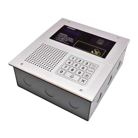
3. Overview 3-1. Feature DRC-481L Description Description Description Display Window (FND) Guard Button Household Interphone (1) RF/ID Receiver (Optional) Cancel Button Household Interphone (2) Speaker Reset Button Video Out Selection Switches Power: DC12V/1A (RF-1A) No. 1: Computer Connection Key Pad Door Release Terminal No. - Page 7 DRC-500L Description Description Description Night Lamp Speaker Security Switch Connection Key Pad Display Window (FND) Power: DC15V/1A(CS-15C) Program Button CCD Camera Reset Button Electronic Key Button Computer Connection Termina Selection Switches Guard Button Guardhouse Interphone Termina No. 1: Computer Connection No.
- Page 8 3-2. Basic Function ✽ RF/ID Receiver (Optional) To open the door using a Remote Cardkey, place the key here. The word ‘oPEn’will display and the door will be released. Audio Guide “Door Opened” Please the Card Here OPEN DOOR ✽ Call Button (E: Enter) This button is used to page households.
- Page 9 ✽ Selection Switches No. 1: Computer Connection Switch (Used for connection with a computer) Connects a computer using network exclusive to DRC-481L. OFF : To connect to a computer via the RS-485 Port with Finger Print Recognition in use. ON : To connect to a computer via an internal network without Finger Print Recognition in...
- Page 10 ● Must Know Before Use! 1) Accessing All Features with the Program Button -When an error has been made as indicated by continuous beeps, please cancel and start again from the beginning. Beep-Beep-Beep Start again from the (Error) beginning 2) Forgotten PIN 2-1.
-
Page 11: Pin Types
4. PIN Types 4-1. Management PIN - This PIN is for use by the person in charge of the Management Office. - By default, this PIN is set as 4321. - For convenience, hereafter management PIN. 4-2. Building PIN - This is the common PIN for each main entrance. - By default, this PIN is set as 1234. -
Page 12: Setting Pin
5. Setting PIN 5-1. Management PIN Setup ✽ P - Old Management PIN - E - 0 - E - New PIN -E ✽ Management PIN must be 4-digits long. ✽ 0000 will not be recognized as a valid PIN. Press the Press the Program button (P). - Page 13 5-2. Building PIN Setup ✽ P - Old Building PIN - E - 1 - E - New PIN - E ✽ Building PIN must be 4-digits long. ✽ 0000 will not be recognized as a valid PIN. Press the Press the Program button (P).
- Page 14 5-3. Household PIN Setup ✽ K - Program Number - E - Household Number - E - Old Household PIN - E - New PIN - P ✽ Household PIN must be 4-digits long. ✽ 0000 will not be recognized as a valid PIN. ✽...
-
Page 15: Household Pin Confirmation
6.Household PIN Confirmation 6-1. Household PIN Confirmation ✽ P - Building (Management) PIN - E - Program Number - E - Household Number - E Press the Press the Program button (P). Enter the Building (Management) PIN. Call button (E). Press the Press the Household Number. -
Page 16: Configuring Building And Serial Numbers In The Main Entrance Interphone
7.Configuring Building and Serial Numbers in the Main Entrance Interphone ✽ This feature must be performed for it automatically configures Building and Serial numbers when Households or the Guardhouse is paged from the Main Entrance. ✽ Up to 99 Main Entrance interphones can be installed per each building. 7-1. - Page 17 7-2. Configuring Serial Number from the Main Entrance Interphone ✽ P - Building (Management) PIN - E - 3 - E - Serial Number - E Press the Program button (P). Press the Enter the Building (Management) PIN. Call button (E). Press the Call button (E).
-
Page 18: Using Remote Cardkeys (Rf/Id) - Optional
8. Using Remote Cardkeys (RF/ID) - Optional 8-1. Testing Remote Cardkeys ✽ P - Building (Management) PIN - E - 9 - E - Card Test - X (Cancel) ✽ This feature is used to test Remote Cardkeys. Press the Press the Program button (P). - Page 19 8-2. Remote Cardkey Registration ✽ P - Building (Management) PIN - E - 10 - E - Card Registration - X (Cancel) Press the Enter the Building (Management) PIN. Press the Program button (P). Call button (E). ex) Building PIN Press the Card Here Press the Press the...
- Page 20 8-3. Individual Deletion of Remote Cardkeys ✽ P - Building (Management) PIN - E - 12 - E - Card Deletion - X (Cancel) Press the Enter the Building (Management) PIN. Press the Program button (P). Call button (E). ex) Building PIN Press the Card Here 1.
- Page 21 8-4. Confirming Remote Cardkey Registration ✽ P - Building (Management) PIN - E - 13 - E - Card Confirmation - X (Cancel) Press the Enter the Building (Management) PIN. Press the Program button (P). Call button (E). ex) Building PIN Press the Press the Card Here Program Number (13).
- Page 22 8-5. All Remote Cardkey deletion ✽ P - Building (Management) PIN - E - 11 - E - E ✽ Refrain from deleting all Remote Cardkeys, except for during installation. Press the Enter the Building (Management) PIN. Press the Program button (P). Call button (E).
- Page 23 8-6. Remote Cardkey Capacity Expansion ✽ P - Building (Management) PIN - E - 19 - E - 0 - E: Maximum 2048 Cards can be registered. ✽ P - Building (Management) PIN - E - 10 - E - 1 - E: Unlimited number of Cards can be registered.
-
Page 24: Surveillance Monitor Configuration
9. Surveillance Monitor Configuration ✽ P - Building (Management) PIN - E - 4 - E - 0 - E: Surveillance disabled. ✽ P - Building (Management) PIN - E - 4 - E - 1 - E: Surveillance enabled. ✽... -
Page 25: Door Release Time Setup
10. Door Release Time Setup ✽ P - Building (Management) PIN - E - 5 - E - Door Release Time - E ✽ This feature adjusts the door release time. Enter the Building (Management) PIN. Press the Press the Program button (P). ex) Building PIN Call button (E). -
Page 26: Page Tone Selection
11. Page Tone Selection ✽ P - Building (Management) PIN - E - 7 - E - 0 - E: Melody Tone ✽ P - Building (Management) PIN - E - 7 - E - 1 - E: Bell (Ringer) ✽... -
Page 27: Wiring Method Selection
12. Wiring Method Selection ✽ P - Building (Management) PIN - E - 6 - E - 4 - E: 4-wire Common Method (12-wire common) ✽ P - Building (Management) PIN - E - 6 - E - 8 - E: 8-wire Common Method ✽... -
Page 28: Video Out Impedance Adjustment
13. Video Out Impedance Adjustment ✽ P - Building (Management) PIN - E - 8 - E - 0 - E: Short Distance ✽ P - Building (Management) PIN - E - 8 - E - 1 - E: Long Distance ✽... -
Page 29: Household Interphone Diagnosis
14. Household Interphone Diagnosis ✽ P - Building (Management) PIN - E - 14 - E - Household Number - E ✽ This feature checks for the Household Interphone’ s operating conditions. Press the Enter the Building (Management) PIN. Press the Program button (P). Call button (E). - Page 30 ① Press the Program button (P). ( ‘Prog’ will appear) ② Enter the Building (Management) PIN. ③ Press the Page button (E). ④ Enter number 14 (Household Interphone Diagnosis). ⑤ Press the Page button (E). ( ‘Subt’ will appear) ⑥ Enter the Household Number, then press the Program button. ⑦...
-
Page 31: Household Number Registration
15. Household Number Registration ✽ P - Building (Management) PIN - E - 15 - E - Guardhouse page from the Household - Household Number - P - Serial Numbe - E ✽ This feature is used to register Household Numbers through the Main Entrance Interphone when the Guardhouse Interphone has not been installed. - Page 32 <Note> ✽ What is Multi Sub Number? Refers to individual numbers for each videophone in the Household when there is more than one. ✽ The Master’ s Serial Number is 0. ✽ Sub Serial Numbers are from 1 to 9. ✽...
-
Page 33: Paging The Household
16. Paging the Household Enter theHousehold Number. Press the page button. A paging tone will sound. ex) unit 101 Press the Call button (E). Wait for a reply 17. Paging the Guardhouse Press the Guard button. Press the Page button. A paging tone will sound. -
Page 34: Door Release Using The Household Pin
18. Door Release Using the Household PIN ✽ Household Number - K - Household PIN - E Enter the Household Number. Press the Electronic key button. ex) To open the door of unit 101 Enter the Household PIN. Press the Page button. Press the Call button (E). -
Page 35: Appendix (Various Program Summaries)
20. Appendix (Various Program Summaries) ✽ Various PIN Programs 1. P - Old Management PIN - E - 0 - E - New PIN- E: Management PIN Change 2. P- Old Building PIN - E -1 - E - New PIN - E: Building PIN Change 3. -
Page 36: Wiring Method
21. Wiring Method 1) Guardhouse Interphone (CDS-481L) For Computer For Internal Connection Phone Line (Optional) Bk: Black Br: Brown R: Red Bk Br R Or Y G B Pu G Bk Br R Or Y G B Pu G Or: Orange Y: Yellow G: Green B: Blue... - Page 37 2) Main Entrance Interphone (DRC-481L) Bk: Black Br: Brown R: Red Or: Orange Y: Yellow G: Green B: Blue Pu: Purple G: Gray Infrared Sensor W: White Guardhouse (Household Videophone) (Household Videophone) Monitor Security Door Release Mechanism Security ① DC 12V used.
- Page 38 (DRC-500L) Bk: Black Br: Brown R: Red Or: Orange Y: Yellow G: Green B: Blue Pu: Purple G: Gray W: White Guardhouse (Household Videophone) (Household Videophone) Monitor Infrared Sensor Door Release Terminal Security ① Use DC 15V. ② It is designed to use a reed switch. When it is not used, connect two lines. ③...
- Page 39 3) Household Videophone(CH-481SL) Bk: Black Telephone Br: Brown R: Red Or: Orange Household Camera Y: Yellow G: Green B: Blue Talk Pu: Purple Main Entrance G: Gray W: White Talk 1 Talk 2 Guardhouse Talk 3 Warring1 Sensor Warring2 Sensor Burglar Emergency Extention...
- Page 40 5) Household Videophone(CAV-50FSD) Bk: Black Telephone Br: Brown R: Red Or: Orange Household Camera Y: Yellow G: Green B: Blue Talk Pu: Purple Main Entrance G: Gray W: White Talk 1 Talk 2 Guardhouse Talk 3 Warring1 Sensor Warring2 Sensor Burglar Emergency Extention...
- Page 41 7) Household Videophone(CAV-501D) Telephone Household Camera Talk Main Entrance Talk 1 Talk 2 Guardhouse Talk 3 Warring1 Sensor Warring2 Burglar Emergency Bk: Black Br: Brown R: Red Or: Orange Y: Yellow Extention G: Green Main Entrance Call B: Blue Pu: Purple G: Gray W: White - 40 -...
- Page 42 8) Household Videophone(CAV-482S) Telephone Household Camera Talk Main Entrance Talk 1 Talk 2 Guardhouse Talk 3 Warring1 Sensor Warring2 Sensor Burglar Emergency Burglar 1 Sensor Burglar 2 Sensor Communication Bk: Black Br: Brown R: Red Or: Orange Power Y: Yellow G: Green B: Blue Pu: Purple...
- Page 43 9) TV-Phone Interface Adaptor(ADT-481) Unit DC Talk 1 Talk 2 Guardhouse Talk 3 Bk: Black Br: Brown R: Red Or: Orange Extention Main Entrance Call Y: Yellow G: Green B: Blue Pu: Purple Guardhouse(CKV-60T) G: Gray W: White Door Release(CKV-60T) Camera 10) Security Interface Adaptor(ADT-482) Power...
- Page 44 11) System Map - 43 -...
- Page 45 12) Wiring Method for Communications with the Guardhouse Bk: Black Br: Brown R: Red Or: Orange Y: Yellow G: Green B: Blue Pu: Purple G: Gray W: White Bk Br R Or Y G B Pu - 44 -...
- Page 46 13) Main Entrance Interphone Wiring Bk: Black Br: Brown R: Red Or: Orange Y: Yellow G: Green B: Blue Pu: Purple G: Gray ※ NOTE W: White Camera 1 1. Main Entrance System •Bk CALL •Br •R •Or VD/IN •Y VD/OUT Camera 2 2.
- Page 47 14) Wiring ADT-481 and CKV-60T Bk: Black Br: Brown R: Red Or: Orange Y: Yellow G: Green B: Blue Pu: Purple G: Gray W: White Guardhouse Guardhouse OPEN/CLOSE OPEN/CLOSE 15) Wiring ADT-482 and CAV-482S Telephone Telephone Household Camera Main Entrance Burglar 1 Burglar 2 Sensor...
- Page 48 16) Installing Numerous Videophones in a Household Multysub Number Multysub Number Multysub Number Multysub Number Household Camera Loby Talk Loby Talk Loby Talk Multysub Number Multysub Number Multysub Number Multysub Number Household Camera Loby Talk Loby Talk Loby Talk ※NOTE 1.
- Page 49 R: Red Y: Yellow B: Blue W: White CAMERA 2 Monitor 2 ※ NOTE 1. Monitor 1: To view only when being used by the Main Entrance Interphone (DRC-481L). 2. Monitor 2: Continuous surveillance of the Main Entrance. - 48 -...
- Page 50 18) Wiring DRC-481L and CDS-481PC - 49 -...
- Page 51 19) Wiring CDS-481PC and Multi Port - 50 -...
-
Page 52: Specifications
22. Specifications Installation Method Flush Mounted Model DRC-481L DRC-500L Specfications Household Videophone (4-wire Common), Guardhouse Interphone (8-wire Common) Transmission System DC12V 1A(RF-1A) AC220V/60Hz or DC15V/1A(CS-15C) Rated Voltage Standby: 200mA, Max: 450mA DC:Standby:400mA, Max:500mA Power Consumption AC:Standby:30mA, Max:50mA Hands Free (One Way) Communication Method B/W C.C.D 1/3″... - Page 53 Sangdaewon-dong, Jungwon-gu, Seongnam-si, Gyeonggi-do, Korea Int’l Business Dept. : Tel.; +82-31-7393-540~550 Fax.; +82-31-745-2133 Web site : www.commax.com Printed In Korea...
Need help?
Do you have a question about the DRC-481L and is the answer not in the manual?
Questions and answers