Table of Contents
Advertisement
Quick Links
Advertisement
Table of Contents

Related Manuals for Lippert Components OneControl Tank Monitor V1


Summary of Contents for Lippert Components OneControl Tank Monitor V1
- Page 1 OneControl Tank Monitor V1 Controller ® OEM INSTALLATION MANUAL...
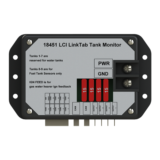
- Page 2 TABLE OF CONTENTS Introduction Safety Resources Required Installation Harness Resistor Pack Operation OneControl Control Panel ® Wiring Diagram Notes Introduction The OneControl® Tank Monitor can be used to monitor up to 9 tanks — 7 water tanks and 2 fuel tanks. The tank monitor also has 4 latching relays that can be used to operate other devices, such as an electric water heater, gas water heater, water pump, or water tank heater.
- Page 3 Installation Mount tank monitor controller (Fig. 1) by securing to a solid surface with #8 x 1" wood screws or equivalent. NOTe: An ideal location can be chosen by the OEM. Connect to DC 12 V power and ground. Connect CANBUS Data wires (in proper sequence with MyRV system components). Connect tank wire harness.
- Page 4 Resistor Pack • White – Ground(-) connect to EMPTY (E) sensor • Yellow – connect to LOW level (1/3) sensor • Green – connect to MID level (2/3) sensor • Red – connect to FULL level (F) sensor • Pink – signal wire connects to “Tank” wire from monitor harness. This wire is connected to the proper input wire on the panel harness.
- Page 5 Operation OneControl ® Control Panel The control panel will operate various devices connected to the OneControl® system. Locate “OneControl® Control Panel” (Fig. 5). Pressing the “OneControl® Control Panel” (Fig. 5A) will open “OneControl® Applications”. Pressing the "Tank Monitor" icon (Fig. 6A) will allow you to access the tank monitor screen (Fig. 7). NOTe: The indicator panel light will be depicted by the use of the tank;...
- Page 6 Wiring Diagram Fig. 8 Tablet Wireless Hub Page 6 Rev: 06.12.19 CCD-0002310...
- Page 7 Notes Page 7 Rev: 06.12.19 CCD-0002310...
- Page 8 The contents of this manual are proprietary and copyright protected by Lippert Components, Inc. (“LCI”). LCI prohibits the copying or dissemination of portions of this manual unless prior written consent from an authorized LCI representative has been provided. Any unauthorized use shall void any applicable warranty. ...
Need help?
Do you have a question about the OneControl Tank Monitor V1 and is the answer not in the manual?
Questions and answers