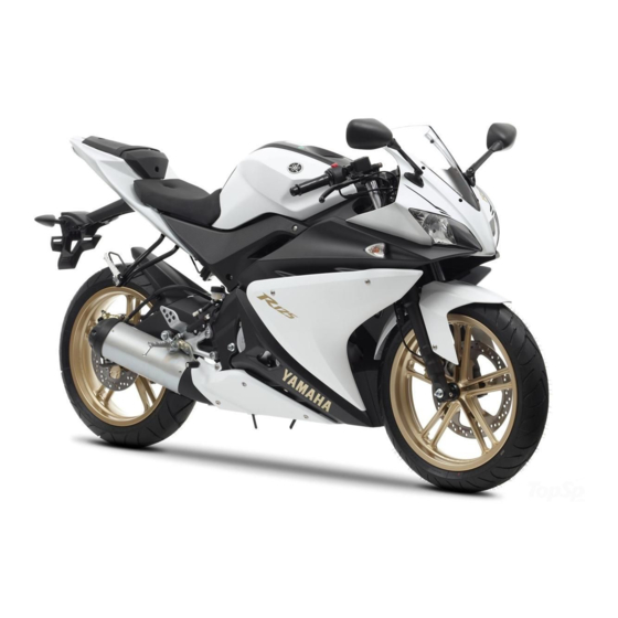
Yamaha YZF-R125 Owner's Manual
Hide thumbs
Also See for YZF-R125:
- Service manual (356 pages) ,
- Owner's manual (96 pages) ,
- Owner's manual (84 pages)

Related Manuals for Yamaha YZF-R125


Summary of Contents for Yamaha YZF-R125
- Page 1 Read this manual carefully before operating this vehicle. OWNER’S MANUAL YZF-R125 YZF-R125A 5D7-F8199-E5...
- Page 2 EAU46091 Read this manual carefully before operating this vehicle. This manual should stay with this vehicle if it is sold.
- Page 3 Yamaha a reputation for dependability. Please take the time to read this manual thoroughly, so as to enjoy all advantages of your YZF-R125/YZF-R125A. The Own- er’s Manual does not only instruct you in how to operate, inspect and maintain your motorcycle, but also in how to safe- guard yourself and others from trouble and injury.
-
Page 4: Important Manual Information
IMPORTANT MANUAL INFORMATION EAU10134 Particularly important information is distinguished in this manual by the following notations: This is the safety alert symbol. It is used to alert you to potential personal injury hazards. Obey all safety messages that follow this symbol to avoid possible injury or death. - Page 5 IMPORTANT MANUAL INFORMATION EAUM1012 YZF-R125/YZF-R125A OWNER’S MANUAL ©2014 by MBK INDUSTRIE 1st edition, July 2014 All rights reserved Any reprinting or unauthorized use without the written permission of MBK INDUSTRIE is expressly prohibited. Printed in France.
-
Page 6: Table Of Contents
TABLE OF CONTENTS SAFETY INFORMATION ....1-1 FOR YOUR SAFETY – Tires ..........6-18 PRE-OPERATION CHECKS .....4-1 Cast wheels ........6-20 DESCRIPTION ........2-1 Adjusting the clutch lever free Left view ......... 2-1 OPERATION AND IMPORTANT play..........6-21 Right view........2-2 RIDING POINTS ........5-1 Checking the front brake lever Controls and instruments .... - Page 7 TABLE OF CONTENTS Battery ...........6-31 Replacing the fuses.......6-33 Replacing a headlight bulb....6-34 Replacing an auxiliary light bulb..6-35 Tail/brake light.......6-35 Replacing a turn signal light bulb ..........6-35 Replacing the license plate light bulb ..........6-36 Supporting the motorcycle....6-36 Front wheel (for non-ABS models) ........6-37 Rear wheel (for non-ABS models) ........6-38...
-
Page 8: Safety Information
SAFETY INFORMATION Never operate a motorcycle with- pears to be very effective in reduc- EAU1028B out proper training or instruction. ing the chance of this type of Take a training course. Beginners accident. Be a Responsible Owner should receive training from a cer- Therefore: As the vehicle’s owner, you are re- tified instructor. - Page 9 SAFETY INFORMATION Many accidents involve inexperi- • Always signal before turning or Protective Apparel enced operators. In fact, many op- changing lanes. Make sure that The majority of fatalities from motorcy- erators who have been involved in other motorists can see you. cle accidents are the result of head in- ...
- Page 10 SAFETY INFORMATION Do not run engine outdoors where Avoid Carbon Monoxide Poisoning When loading within this weight limit, All engine exhaust contains carbon engine exhaust can be drawn into keep the following in mind: Cargo and accessory weight monoxide, a deadly gas.
- Page 11 Yamaha accessories, which are avail- performed to your vehicle that change able only from a Yamaha dealer, have any of the vehicle’s design or operation should be kept to a minimum. been designed, tested, and approved characteristics can put you and others •...
- Page 12 SAFETY INFORMATION Check that the fuel cock (if operator and may limit control ability, therefore, such accesso- equipped) is in the “OFF” position ries are not recommended. and that there are no fuel leaks. Use caution when adding electri- ...
-
Page 13: Description
DESCRIPTION EAU10411 Left view 1. Battery (page 6-31) 2. Owner’s tool kit (for ABS models) (page 6-2) 3. Owner’s tool kit (page 6-2) 4. Fuse box (page 6-33) 5. Shift pedal (page 3-13) 6. Engine oil drain bolt (page 6-11) 7. -
Page 14: Right View
DESCRIPTION EAU10421 Right view 1. Front brake fluid reservoir (page 6-24) 2. Spark plug (page 6-10) 3. Engine oil filter element (page 6-11) 4. Dipstick (page 6-11) 5. Rear brake fluid reservoir (page 6-24) 6. Brake pedal (page 3-14) -
Page 15: Controls And Instruments
DESCRIPTION EAU10431 Controls and instruments 1. Clutch lever (page 3-13) 2. Left handlebar switches (page 3-11) 3. Multi-function meter unit (page 3-4) 4. Main switch/steering lock (page 3-1) 5. Right handlebar switches (page 3-11) 6. Throttle grip (page 6-17) 7. Brake lever (page 3-13) -
Page 16: Instrument And Control Functions
INSTRUMENT AND CONTROL FUNCTIONS To lock the steering EAU10462 EAU10662 Main switch/steering lock All electrical systems are off. The key can be removed. EWA10062 WARNING Never turn the key to “OFF” or “LOCK” while the vehicle is moving. Otherwise the electrical systems will be switched off, which may result in loss of control or an accident. -
Page 17: Indicator Lights And Warning Lights
” (for ABS models) 1. Turn the key to “ON”. 2. If the warning light does not come EAU11021 on, have a Yamaha dealer check Turn signal indicator light “ ” the electrical circuit. This indicator light flashes when the turn signal switch is pushed to the left or right. - Page 18 The ABS may not work correctly. If any damage. gine is not working correctly. If this oc- of the above occurs, have a Yamaha To activate or deactivate the tachome- curs, have a Yamaha dealer check the dealer check the system as soon as ter high-rpm warning light, hold the self-diagnosis system.
-
Page 19: Multi-Function Meter Unit
INSTRUMENT AND CONTROL FUNCTIONS a tachometer EAUM3422 Multi-function meter unit a clock a fuel meter FTRIP x1000r/min a coolant temperature meter km/h km/L/100km an odometer and tripmeter display a multi-function display RESET SELECT x1000r/min ... - Page 20 INSTRUMENT AND CONTROL FUNCTIONS ton to switch between kilometers High-rpm zone: 10000 r/min and 6. Push the “SELECT” button and and miles and then press the “SE- above then release it to start the clock. LECT” button for two seconds to confirm the setting.
- Page 21 6-43 for further instruction. 3. Coolant temperature meter go off for 3 seconds repeatedly. If this occurs, have a Yamaha dealer check With the key in the “ON” position, the Odometer and tripmeter display the electrical circuit.
- Page 22 INSTRUMENT AND CONTROL FUNCTIONS two tripmeters (which shows the change to the fuel reserve tripmeter Multi-function display distance traveled since last set to mode “F TRIP” and start counting the zero) distance traveled from that point. In a fuel reserve tripmeter (which that case, pushing the “SELECT”...
- Page 23 INSTRUMENT AND CONTROL FUNCTIONS a warning message function “L/100 km”: The amount of fuel speed “AVE SPEED/__mph”, the oil a self-diagnosis device service reminder “DIST SERV/__miles” necessary to travel 100 km under in the following order: the current riding conditions is Push the “INFO”...
- Page 24 INSTRUMENT AND CONTROL FUNCTIONS the UK only). Push the “INFO” button Average speed display play will also reset automatically 4 to switch between these display set- hours after the key was last turned to tings. “OFF”. “AVE_ _._ km/L”: The average dis- tance that can be traveled on 1.0 L Time tripmeter of fuel is shown.
- Page 25 If the low battery indicator comes on SERV” mode flashes and then push ter that, and every 3000 km thereafter. have a Yamaha dealer check the bat- and hold the “RESET” button for at After changing the engine oil, reset the tery.
-
Page 26: Handlebar Switches
If the display indicates any error codes, HIGH TEMP →LOW FUEL →LOW note the code number, and then have BATT →OIL SERV a Yamaha dealer check the vehicle. ECA11591 NOTICE Push the “INFO” button to switch be- If the display indicates an error... - Page 27 INSTRUMENT AND CONTROL FUNCTIONS Right ter position. To cancel the turn signal EAUM3451 Info switch “INFO” lights, push the switch in after it has re- This switch is used to perform selec- turned to the center position. tions in the function display of the multi-function meter unit and to acti- EAU12501 Horn switch “...
-
Page 28: Clutch Lever
INSTRUMENT AND CONTROL FUNCTIONS EAU12821 EAU12872 EAU12892 Clutch lever Shift pedal Brake lever ZAUM1164 ZAUM1165 ZAUM1166 1. Clutch lever 1. Shift pedal 1. Brake lever The clutch lever is located at the left The shift pedal is located on the left The brake lever is located on the right handlebar grip. -
Page 29: Brake Pedal
EAU60021 Brake pedal ABS (for ABS models) The ABS performs a self-diagno- The Yamaha ABS (Anti-lock Brake sis test each time the vehicle first System) features a dual electronic con- starts off after the key is turned to trol system, which acts on the front and “ON”... -
Page 30: Fuel Tank Cap
INSTRUMENT AND CONTROL FUNCTIONS EAUM2082 Fuel tank cap The fuel tank cap cannot be installed unless the key is in the lock. In addi- tion, the key cannot be removed if the cap is not properly installed and locked. EWA11142 WARNING ZAUM1227 Make sure that the fuel tank cap is... -
Page 31: Fuel
Gasoline is poisonous and can fuel expands when it heats up, Your Yamaha engine has been de- cause injury or death. Handle gaso- heat from the engine or the sun signed to use premium unleaded gas- line with care. -
Page 32: Catalytic Converter
10% (E10). Gas- Do not park the vehicle near ohol containing methanol is possible fire hazards such as recommended by Yamaha because it grass or other materials that can cause damage to the fuel system easily burn. or vehicle performance problems. -
Page 33: Rider Seat
Yamaha’s ignition circuit cut-off system has been designed to assist the operator in fulfilling the respon- sibility of raising the sidestand be- fore starting off. -
Page 34: Ignition Circuit Cut-Off System
INSTRUMENT AND CONTROL FUNCTIONS this system regularly and have a EAU44893 Ignition circuit cut-off system Yamaha dealer repair it if it does not The ignition circuit cut-off system function properly. (comprising the sidestand switch, clutch switch and neutral switch) has the following functions. - Page 35 INSTRUMENT AND CONTROL FUNCTIONS WARNING With the engine turned off: 1. Move the sidestand down. If a malfunction is noted, have a Yamaha 2. Make sure that the engine stop switch is set to “ ”. dealer check the system before riding.
-
Page 36: For Your Safety - Pre-Operation Checks
• If necessary, add recommended coolant to specified level. 6-14 • Check cooling system for leakage. • Check operation. • If soft or spongy, have Yamaha dealer bleed hydraulic system. • Check brake pads for wear. Front brake • Replace if necessary. - Page 37 • Make sure that operation is smooth. • Check throttle grip free play. Throttle grip 6-17, 6-28 • If necessary, have Yamaha dealer adjust throttle grip free play and lubricate ca- ble and grip housing. • Make sure that operation is smooth. Control cables 6-27 •...
- Page 38 • Correct if necessary. • Check operation of ignition circuit cut-off system. Sidestand switch 3-18 • If system is not working correctly, have Yamaha dealer check vehicle. • Check fluid level. 6-31 Battery • Fill with distilled water if necessary.
-
Page 39: Operation And Important Riding Points
The transmission is in the neutral understand, ask your Yamaha dealer. a turnover. In this case, the multi-func- EWA10272 position. -
Page 40: Shifting
The neutral indi- repeatedly until it reaches the end of its cator light should come on. If not, travel, and then slightly raise it. ask a Yamaha dealer to check the electrical circuit. 3. Start the engine by pushing the start switch. -
Page 41: Tips For Reducing Fuel Consumption
OPERATION AND IMPORTANT RIDING POINTS ECA10261 EAU16811 EAU16831 Tips for reducing fuel con- Engine break-in NOTICE sumption There is never a more important period Even with the transmission in in the life of your engine than the period Fuel consumption depends largely on the neutral position, do not between 0 and 1000 km (600 mi). -
Page 42: Parking
Do not park near grass or other Keep the engine speed out of flammable materials which the tachometer red zone. might catch fire. If any engine trouble should oc- cur during the engine break-in period, immediately have a Yamaha dealer check the vehi- cle. -
Page 43: Periodic Maintenance And Adjustment
To avoid possible burns, let tivities incorrectly may increase brake components cool before your risk of injury or death during touching them. service or while using the vehicle. If you are not familiar with vehicle ser- vice, have a Yamaha dealer perform service. -
Page 44: Owner's Tool Kit
If you do not have the tools or experi- ence required for a particular job, have a Yamaha dealer perform it for you. -
Page 45: Periodic Maintenance Chart For The Emission Control System
From 30000 km (17500 mi), repeat the maintenance intervals starting from 6000 km (3500 mi). Items marked with an asterisk should be performed by a Yamaha dealer as they require special tools, data and tech- nical skills. -
Page 46: General Maintenance And Lubrication Chart
PERIODIC MAINTENANCE AND ADJUSTMENT EAU1771A General maintenance and lubrication chart ODOMETER READING ANNUAL ITEM CHECK OR MAINTENANCE JOB 1000 km 6000 km 12000 km 18000 km 24000 km CHECK (600 mi) (3500 mi) (7000 mi) (10500 mi) (14000 mi) √ √... - Page 47 PERIODIC MAINTENANCE AND ADJUSTMENT ODOMETER READING ANNUAL ITEM CHECK OR MAINTENANCE JOB 1000 km 6000 km 12000 km 18000 km 24000 km CHECK (600 mi) (3500 mi) (7000 mi) (10500 mi) (14000 mi) • Check tread depth and for dam- age.
- Page 48 PERIODIC MAINTENANCE AND ADJUSTMENT ODOMETER READING ANNUAL ITEM CHECK OR MAINTENANCE JOB 1000 km 6000 km 12000 km 18000 km 24000 km CHECK (600 mi) (3500 mi) (7000 mi) (10500 mi) (14000 mi) • Check operation. √ √ √ √ √...
- Page 49 PERIODIC MAINTENANCE AND ADJUSTMENT ODOMETER READING ANNUAL ITEM CHECK OR MAINTENANCE JOB 1000 km 6000 km 12000 km 18000 km 24000 km CHECK (600 mi) (3500 mi) (7000 mi) (10500 mi) (14000 mi) • Check operation. • Check throttle grip free play, and √...
-
Page 50: Removing And Installing The Cowlings And Panel
PERIODIC MAINTENANCE AND ADJUSTMENT 2. Remove the screws, slide the EAU18732 EAU55850 Removing and installing the cowling forward, and then take it cowlings and panel off. Cowling A 3. Disconnect the turn signal light lead coupler. To remove the cowling Remove the screws, and then take the cowling off. - Page 51 PERIODIC MAINTENANCE AND ADJUSTMENT Cowling C 2. Remove the screws and the quick fasteners, and then take the cowl- To install the quick fasteners, push the To remove the cowling ing off. center pin out so that it will protrude Remove the screws, and then pull the from the fastener head, insert the fas- cowling off as shown.
-
Page 52: Checking The Spark Plug
If the spark plug shows a distinctly dif- ferent color, the engine could be oper- ating improperly. Do not attempt to diagnose such problems yourself. In- 1. Spark plug cap stead, have a Yamaha dealer check the vehicle. 6-10... -
Page 53: Engine Oil And Oil Filter Element
PERIODIC MAINTENANCE AND ADJUSTMENT 2. Check the spark plug for electrode 2. Clean the surface of the spark EAUM3490 Engine oil and oil filter ele- erosion and excessive carbon or plug gasket and its mating sur- ment other deposits, and replace it if face, and then wipe off any grime The engine oil level should be checked necessary. - Page 54 PERIODIC MAINTENANCE AND ADJUSTMENT 4. If the engine oil is below the mini- mum level mark, add sufficient oil The engine oil should be between the of the recommended type to raise minimum and maximum level marks. it to the correct level. 5.
- Page 55 PERIODIC MAINTENANCE AND ADJUSTMENT 9. Install the oil filter element cover by installing the bolts, then tight- ening them to the specified torque. Tightening torques: Oil filter element cover bolt: 10 Nm (1.0 m·kgf, 7.2 ft·lbf) 1. Engine oil drain bolt 1.
-
Page 56: Coolant
PERIODIC MAINTENANCE AND ADJUSTMENT 11. Refill with the specified amount of 12. Start the engine, and then let it idle EAU20071 Coolant the recommended engine oil, and for several minutes while checking The coolant level should be checked then install and tighten the oil filler it for oil leakage. - Page 57 3. Minimum level mark tenance and lubrication chart. Have a mark, and then install the reservoir Yamaha dealer change the coolant. cap. NOTICE: If coolant is not 3. If the coolant is at or below the WARNING! Never attempt to remove...
-
Page 58: Replacing The Air Filter Element And Cleaning The Check Hose
Yamaha dealer. placed at the intervals specified in the periodic maintenance and lubrication Engine idling speed: chart. Have a Yamaha dealer replace 1350–1550 r/min the air filter element more frequently if you are riding in unusually wet or dusty areas. In addition, the air filter check hose must be frequently checked and cleaned if necessary. -
Page 59: Adjusting The Throttle Grip Free Play
To prevent this nut in direction (b). from occurring, the valve clearance must be adjusted by a Yamaha dealer at the intervals specified in the periodic maintenance and lubrication chart. ZAUM1177 1. -
Page 60: Tires
* Total weight of rider, passenger, car- or glass fragments in it, or if the side- go and accessories Operation of this vehicle with im- wall is cracked, have a Yamaha dealer proper tire pressure may cause se- replace the tire immediately. EWA10512... - Page 61 PERIODIC MAINTENANCE AND ADJUSTMENT Tire information EWA10472 EWA10902 WARNING WARNING Have a Yamaha dealer replace The front and rear tires should excessively worn tires. Besides be of the same make and de- being illegal, operating the vehi- sign, otherwise the handling...
-
Page 62: Cast Wheels
If any damage is found, have V3002 (original) speed riding to ride conserva- Rear tire: a Yamaha dealer replace the tively for approximately 100 km Size: wheel. Do not attempt even the (60 mi) after installing a new tire. -
Page 63: Adjusting The Clutch Lever Free Play
PERIODIC MAINTENANCE AND ADJUSTMENT 7. Tighten the locknut at the crank- EAU22045 Adjusting the clutch lever free case. If the specified clutch lever free play play 8. Tighten the locknut at the clutch could be obtained as described above, lever and then slide the rubber skip steps 4–7. -
Page 64: Checking The Front Brake Lever Free Play
Yamaha dealer check the brake sys- a Yamaha dealer adjust it. takes effect. If necessary, adjust the tem. -
Page 65: Checking The Front And Rear Brake Pads
EAU22393 Checking the front and rear brake light come on later, turn the ad- peared, have a Yamaha dealer replace brake pads justing nut in direction (b). the brake pads as a set. The front and rear brake pads must be... -
Page 66: Checking The Brake Fluid Level
PERIODIC MAINTENANCE AND ADJUSTMENT Use only the specified brake flu- Rear brake EAU40262 Checking the brake fluid level id; otherwise, the rubber seals Before riding, check that the brake fluid may deteriorate, causing leak- is above the minimum level mark. age. -
Page 67: Changing The Brake Fluid
EAU22733 EAU22762 Changing the brake fluid Drive chain slack Yamaha dealer check the cause before Have a Yamaha dealer change the The drive chain slack should be further riding. brake fluid at the intervals specified in... - Page 68 To adjust the drive chain slack Locknut: drive chain slack adjusting bolt on 16 Nm (1.6 m·kgf, 12 ft·lbf) Consult a Yamaha dealer before ad- each side of the swingarm in di- justing the drive chain slack. rection (a). To loosen the drive 4.
-
Page 69: Cleaning And Lubricating The Drive Chain
If a cable is wet areas. Service the drive chain as damaged or does not move smoothly, follows. have a Yamaha dealer check or re- place it. WARNING! Damage to the ECA10584 NOTICE outer housing of cables may result... -
Page 70: Checking And Lubricating The Throttle Grip And Cable
In levers should be checked before each addition, the cable should be lubricat- ride, and the lever pivots should be lu- ed by a Yamaha dealer at the intervals bricated if necessary. specified in the periodic maintenance Brake lever chart. -
Page 71: Checking And Lubricating The Brake Pedal
The operation of the brake pedal The swingarm pivots must be lubricat- should be checked before each ride, ed by a Yamaha dealer at the intervals and the pedal pivot should be lubricat- specified in the periodic maintenance ed if necessary. -
Page 72: Checking The Front Fork
WARNING! To avoid injury, of it falling over. have a Yamaha dealer check or re- [EWA10752] securely support the vehicle so 2. Hold the lower ends of the front pair it. -
Page 73: Checking The Wheel Bearings
If there is play in the wheel skin, eyes or clothing and al- hub or if the wheel does not turn ways shield your eyes when smoothly, have a Yamaha dealer working near batteries. In case check the wheel bearings. of contact, administer the fol- lowing FIRST AID. - Page 74 PERIODIC MAINTENANCE AND ADJUSTMENT Batteries produce explosive hy- To store the battery drogen gas. Therefore, keep 1. If the motorcycle will not be used The electrolyte should be between the for more than one month, remove sparks, flames, cigarettes, etc., minimum and maximum level marks.
-
Page 75: Replacing The Fuses
(See page tery, the frame could suffer 3-18.) structural and external damag- YZF-R125 1 2 3 4 5 [ECA10602] ZAUM1188 ZAUM1189 1. Fuse box 1. Headlight fuse 2. -
Page 76: Replacing A Headlight Bulb
Main fuse: This model is equipped with halogen 20.0 A bulb headlights. If a headlight bulb Ignition fuse: burns out, have a Yamaha dealer re- 7.5 A Signaling system fuse: place it and, if necessary, adjust the 7.5 A headlight beam. -
Page 77: Replacing An Auxiliary Light Bulb
If the tail/brake light does not come on, iary lights. If an auxiliary light bulb by removing the screw. have a Yamaha dealer check it. burns out, replace it as follows. 1. Remove the auxiliary light bulb socket (together with the bulb) by pulling it out. -
Page 78: Replacing The License Plate Light Bulb
PERIODIC MAINTENANCE AND ADJUSTMENT EAUM3510 EAU24351 Replacing the license plate Supporting the motorcycle light bulb Since this model is not equipped with a centerstand, follow these precautions 1. Remove the license plate light unit when removing the front and rear by removing the screw. -
Page 79: Front Wheel (For Non-Abs Models)
EWA14841 WARNING For the ABS model, have a Yamaha dealer remove and install the wheel. EAU56531 ZAUM1215 1. Axle bolt 2. Front wheel axle pinch bolt A To remove the front wheel 3. -
Page 80: Rear Wheel (For Non-Abs Models)
EWA14841 wheel and brake disc have been the specified torques. WARNING removed, otherwise the brake For the ABS model, have a Yamaha Tightening torques: pads will be forced shut. [ECA11073] Wheel axle: dealer remove and install the wheel. - Page 81 PERIODIC MAINTENANCE AND ADJUSTMENT If the drive chain is difficult to re- move, remove the wheel axle first, and then lift the wheel upward enough to remove the drive chain from the rear sprocket. The drive chain cannot be disas- sembled.
-
Page 82: Troubleshooting
The following troubleshooting charts represent quick and easy procedures for checking these vital systems your- self. However, should your motorcycle require any repair, take it to a Yamaha 1. Retainer dealer, whose skilled technicians have 2. Slot the necessary tools, experience, and 2. - Page 83 PERIODIC MAINTENANCE AND ADJUSTMENT heaters or furnaces. Gasoline or gasoline vapors can ignite or ex- plode, causing severe injury or prop- erty damage. 6-41...
-
Page 84: Troubleshooting Charts
Remove the spark plug and check the electrodes. The engine does not start. Have a Yamaha dealer check the vehicle. Check the battery. 4. Battery The engine turns over The battery is good. - Page 85 Start the engine. If the engine overheats again, have a The coolant level Yamaha dealer check and repair the cooling system. is OK. If coolant is not available, tap water can be temporarily used instead, provided that it is changed to the recommended cool- ant as soon as possible.
-
Page 86: Motorcycle Care And Storage
Some models are equipped with matte colored finished parts. Be ble. Rust and corrosion can develop Cleaning sure to consult a Yamaha dealer for even if high-quality components are ECA10773 NOTICE used. A rusty exhaust pipe may go un-... - Page 87 MOTORCYCLE CARE AND STORAGE off any detergent residue using shield. Test the product on a plenty of water, as it is harmful small hidden part of the wind- Salt sprayed on roads in the winter to plastic parts. shield to make sure that it does may remain well into spring.
-
Page 88: Storage
EWA11132 poorly ventilated room or cover- WARNING ing it with a tarp, while it is still Consult a Yamaha dealer for ad- Contaminants on the brakes or tires wet, will allow water and humid- can cause loss of control. - Page 89 MOTORCYCLE CARE AND STORAGE 2. Fill up the fuel tank and add fuel e. Remove the spark plug cap stabilizer (if available) to prevent from the spark plug, and then Make any necessary repairs before the fuel tank from rusting and the install the spark plug and the storing the motorcycle.
-
Page 90: Specifications
Spark plug gap: –20 –10 0 10 20 30 40 50 ˚C Curb weight: 0.7–0.8 mm (0.028–0.031 in) YZF-R125 140 kg (309 lb) Clutch: Recommended engine oil grade: YZF-R125A 142 kg (313 lb) Clutch type: API service SG type or higher, JASO... - Page 91 SPECIFICATIONS 2nd: Manufacturer/model: Front brake: 30/16 (1.875) PIRELLI/SPORT DEMON Type: 3rd: Manufacturer/model: Single disc brake 30/22 (1.364) MICHELIN/PILOT STREET Operation: 4th: Loading: Right hand operation 24/21 (1.143) Maximum load: Specified brake fluid: 5th: 180 kg (397 lb) DOT 4 22/23 (0.957) (Total weight of rider, passenger, cargo Rear brake: 6th:...
- Page 92 SPECIFICATIONS Battery: ABS warning light: YZF-R125A LED Model: Fuses: 12N5.5-4A / YUASA Voltage, capacity: Main fuse: 12 V, 5.5 Ah 20.0 A Headlight: Headlight fuse: 15.0 A Bulb type: Signaling system fuse: Halogen bulb Bulb voltage, wattage × quantity: 7.5 A Ignition fuse: Headlight: 12 V, 55.0 W ×...
-
Page 93: Consumer Information
Model label Record the vehicle identification num- ber and model label information in the spaces provided below for assistance when ordering spare parts from a Yamaha dealer or for reference in case the vehicle is stolen. VEHICLE IDENTIFICATION NUMBER: ZAUM1195 ZAUM1225 1. -
Page 94: Index
INDEX Engine oil and oil filter element .... 6-11 Engine stop switch ....... 3-12 ABS (for ABS models)......3-14 Parking ............5-4 Engine trouble warning light....3-3 ABS warning light (for ABS models) ..3-3 Part locations ..........2-1 Air filter element and check hose, Pass switch ...........3-12 replacing and cleaning .......6-16 Front and rear brake pads, checking ... - Page 95 INDEX Vehicle identification number ....9-1 Wheel bearings, checking ....6-31 Wheel, front (for non-ABS models)..6-37 Wheel, rear (for non-ABS models)..6-38 Wheels..........6-20 10-2...
- Page 98 Original instructions MBK Industrie Z.I. de Rouvroy 02100 Saint Quentin PRINTED IN FRANCE 2014.09 (E)
Need help?
Do you have a question about the YZF-R125 and is the answer not in the manual?
Questions and answers