Table of Contents
Advertisement
Advertisement
Table of Contents

Subscribe to Our Youtube Channel
Related Manuals for Royal Sovereign RSC-5500H


Summary of Contents for Royal Sovereign RSC-5500H
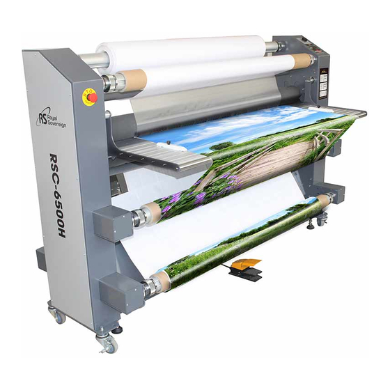
- Page 1 MODEL: RSC-5500H/RSC-6500H Roll Laminator Service Manual www.royalsovereign.com...
-
Page 2: Table Of Contents
Table of Content 1.Safety Precautions ……………………………………………………………………… 3 ~ 3 2.Troubleshooting …………………………………………………………………………… 4 ~ 10 2.1) Roller Not Heating ……………………………………………………………………………… 4 ~ 6 2.2) Roller Over Heating …………………………………………………………………………… 6 ~ 7 2.3) Rollers Not Running ……………………………………………………………………………… 7 ~ 10 2.4) No Main Power …………………………………………………………………………………… 10 ~ 10 3.Replacing Parts ………………………………………………………………………………... -
Page 3: Safety Precautions
7. Ensure the unit is turned off, cooled ,and unplugged from the outlet prior to moving and/or repairing. 8. Keep out of reach of children. 9. Only Royal Sovereign authorized maintenance and service technicians should make repairs. 10. Do not attempt to laminate items that exceed total recommended material thickness for the unit. -
Page 4: Troubleshooting
2. Troubleshooting Note: While repairing: Make sure the power plug is unplugged from the power outlet. Open both side covers and right stand cover. Be sure to follow the steps below in order. 2.1 Roller Not Heating CAUSES: 1. Improper laminating mode. 2. - Page 5 3. Broken Temperature Bi-Metal. a. Replace the Temperature Bi-Metal located in the right-hand side of the machine. Temp Bi-Metal 4. Defective Tempreature sensor a. Replace the temp. sensor set on the shaft behind the up roller. UP-ROLLER TEMP-SENSOR 5. Defective heater. a.
-
Page 6: Roller Over Heating
6. Defective Main PCB. a. Replace the PCB Main.() Main-PCB 2.2) Roller Over Heating CAUSES 1. Defective Tempreature sensor. 2. Defective Main-PCB. MEASURES 1. Defective Tempreature sensor. a.Replace the Tempreature sensor. -
Page 7: Rollers Not Running
2. Defective Main-PCB. a. Replace the Main-PCB Main-PCB 2.3) Rollers Not Running CAUSES 1. No power to the unit. 2. Emergency switch is engaged. 3. Film is jammed on the rollers. 4. Opened Front Table Switch. 5. Laser sensor detect the danger or it is not in correct work place. 6. - Page 8 2. Emergency switch is engaged. a. Disengage the emergency switches located on the front of Cover-L by rotating the knob clock-wise. Emergency-Switch Emergency-Switch 3. Film is jammed on the rollers. a. Un-jam the film using a combination of the Pressure lever and reverse button. Pressure-lever...
- Page 9 4. Opened Front Table Switch. a.Check that Front table Switch is engaged to ensure The machine is in working state. Switch is engaged 5. Laser sensor detect the danger or it is not in correct work place. a. Make sure laser sensor is in correct work position, and clean up things could mislead laser sensor Stop the roller.
-
Page 10: No Main Power
* 8. Defective Motor-controller * The Roller run while press the"SLOW" button,but not run while press the"RUN" button a. Cheek if the connnector of the wire-motor controller is connnect correctly. b. If it doesn't work ,Replace the Motor controller with a new one. 2.4) No Main Power CAUSES 1. -
Page 11: Replacing Parts
3. Replacing Parts Note: While replacing parts: a. Make sure the power plug is unplugged from the power outlet. b. Open both side covers and right stand cover. 3.1 Replacing the Right or Left Cover. a. Take out 9 cover screws using screw driver. Figure 2 Figure 1 b.Replacing it with a new one. - Page 12 Chain-A Special Chain-link Chain-B c. Take out 6 Hexa-bolt located on the Frame-L and disassemble the Motor-system Hexa-Bolt c.Remove the motor and replace it with a new one. c. Follow the reverse order to assmble the Motor. 3.2.2 Replacing The Motor controller...
-
Page 13: 2) Motor Controller
a. Remove right-cover .(Refer to 3.1 Replacing right or left cover) b. Disassmble Cover-Motor control and unfasten 2 nuts showing in the Motor-controller picture . Cover-Motor Controller Nut-A Nut-B Connector c. Remove the connnector of the controller and replace it with a good one. d. -
Page 14: Heater
b.Disassemble 4 bolts showing in the photo, remove the wire heater and take out the insulating strip. Frame-R Frame-L insulating strip Screw Wire-Heater Wire-Heater c.Remove the heater and replace it with a new one. d.Follow the reverse order to reassmble insulating strip and wire-heater. 3.4 Replacing the Sub-PCB a. -
Page 15: 1) Rubber Strip
3.5 Replacing the Rubber Strip and The friction plate 3.5.1 Replacing the Rubber Strip . Holder-rubber strip Rubber Strip a. Remove the Shaft film b. Take out the holder-rubber strip by gently tapping a appropriate tool putting into the hole and replace rubber strip with a new one. 3.5.2 Replacing the The friction plate . -
Page 16: 2) Friction Plate
1.Disassemble C-ring showing in Figure 3 with circlip pliers. C-ring C-ring C-ring Sprocket Figure 2 Figure 3 b.Remove friction-plate and replace it with a new one after Disassmble handle-tension ,spring and plate. (Figure 4) Handle-tension Spring plate Friction-plate Figure 4 c. -
Page 17: Roller
d. In the reverse order to reassmble the new front-table 3.7 Replacing the Roller Situation 1: <Replacing Roller-up>. a. Remove the Left cover and Right cover .(Refer to "3.1 Replacing the right or left cover") b.Rotate the Front-table to make room for taking roller out .(Figure-5) c. -
Page 18: Main Pcb And Transformer
f. Reassemble The roller by reverse order showing above. Situation 2: <Replacing Roller-low>. a. Remove up roller (refer to replacing roller ) b. Accroding to picture showing below to take out Roller-low Bearing washer-plain Roller-low c. Replace Roller-low with a new one. d. - Page 19 d. Tighten the Screws and Reconnect the connnectors to the PCB. 3.8.2 Replacing The Transformer a.Disassmble right-cover () b. Unfasten all Screw showing in the photo circled with Screw the red dotted line and disconnect the connnectors c. Change the Transformer d.
-
Page 20: Sensor
f. Replace the sensor with a good one. Sensor... - Page 21 3. Replacing Parts...
- Page 23 controller...
- Page 24 g in the photo, remove the wire heater and take out the insulating strip.
- Page 26 eplace it with a new one after Disassmble handle-tension ,spring and plate. disconnect the connector.After that , push the table towards direction of...
- Page 27 ring pressure...
-
Page 31: Adjustments
4. Adjustments 4.1 Adjusting Release liner Shaft Speed CAUSES: 1.Main rollers and Release liner shaft speed is not synchronized. MEASURES: Adjust Release liner shaft speed by loosenning or tightenning the Handle-Tension Tighten–Rotate the plate-pressure accroding to yellow arrow shows in below picture. Lossen–Rotate the plate-pressure accroding to red arrow shows in below picture. - Page 32 3.Pressure mark checking (Heat Line) stop the machine for 30 seconds to create a heat line. Then check to see if you have two even parallel lines from one end to other. Note: A narrow parallel lines indicate that it has less pressure at that point.
-
Page 33: Parts List
SVC Parts List RSC-5500/6500 "X" NOT USE Changing Remark Part No. Part Name Spec. 5500H 6500H P/NO. Date 013LR2183A FRAME-L SPHC 4.5T PANTONE 431C 013LR2012P SHAFT SENSOR AL6063 PANTONE 431C 013LR2012R SHAFT SENSOR AL6063 PANTONE 431C 013LR2178C SHAFT AUTO GRIP 3" AL6063 013LR2178D SHAFT AUTO GRIP 3"... - Page 34 EU DONG-A 23300X001A BUSHING-CORD(电源线扣) (厂家规格 7P-2黑色电源线扣) 350LR3055A SUB PCB FR-4 36400X002B SWITCH-MAIN(主开关) AC250 16A CANAL ELECTRICAL 36400X018A SWITCH-EMERGENCY AC240V 3A MICRO S/W(微型开关) SC799 364CCX003A SWITCH FOOT 380V 15A 365LR4006A 380CR4004A POWER CORD(电源线) CUL AC125V 15A 1.8M 445020015A BELLEVILLE SPRING(碟形弹簧) 40*20.4*1.5T ASMLR1606A ASM SENSOR 133LR2096A...
- Page 35 021LR3038A HOUSE PLECTRUM SWITCH 耐热ABS BLACK 021LR4045A PLECTRUM SWITCH 耐热 ABS BLACK 023LR4002A KNOB-BOLT GUIDE(把手) PHENOL BLK 111LR4006A BOLT-GUIDE S45C SNC3 4*22.5(镀锌) DU BUSH FLANGE Ф35*10 12200X049A SPRING-SLIP(弹簧) SWRH φ3.5 ZWP5 (镀白锌) 138LR4006A HOLDER BRACKET TABLE FRONT,R S45C Cu.Ni.Cr 140LR4063A 140LR4066A HOLDER PIPE S45C Cu.Ni.Cr...
- Page 36 381LR4161A WIRE-PRESSURE SENSOR WIRE: UL1015 AWG 24 381LR4162A WIRE-SPEED ADJUSTER WIRE: UL1015 AWG 24 381LR4163A WIRE-EMERGENCY SWITCH WIRE: UL1015 AWG 22 381LR4164A WIRE-ACC SENSOR WIRE: UL1015 AWG 22 WIRE-EARTH WIRE: UL1015 AWG14 381LR4165A WIRE-LASER SENSOR WIRE: UL1015 AWG 24 381LR4166A HANDLE WHEEL OD160,SHAFT16mm 023LR3010A...
- Page 38 Expolde View...
-
Page 39: Wire Diagram
7. Wire Diagram MAIN PCB Schematic... - Page 40 SUB PCB Schematic...
- Page 41 Main-PCB Layout Power-Transformer T-FUSE...
- Page 42 <Connect part> 1.WIRE-ACC SENSOR 6.WIRE-KEY SUB PCB 11.WIRE-LASER SENSOR 1 16.WIRE-P/T INPUT 2.WIRE-PRESSURE 7.WIRE-FOOT 12.WIRE-LASER SENSOR 2 3 WIRE-TEMP.SENSOR 8.WIRE-HEATER UP 13.WIRE-P/T OUTPUT 4.WIRE-MOTOR 9.WIRE-AC INPUT 14.WIRE-EMEGENCY SWITCH 5.WIRE-MAIN SUB PCB 10.WIRE-FAN 15.WIRE-EMEGENCY SWITCH...
- Page 43 < Frame-R Layout> <connnect part> 1.WIRE-LASER SENSOR 2 4.WIRE-MICRO SWITCH 2.WIRE-BI METAL 5.MICRO SWITCH 3.WIRE-PRESSURE 5.WIRE-ACC SENSOR...
- Page 44 <Frame-L Layout> <connnect part> 1.WIRE-MOTOR 3.WIRE-HEATER 2.WIRE-LASER SENSOR 1 4.WIRE-EMERGENCY SWITCH...
Need help?
Do you have a question about the RSC-5500H and is the answer not in the manual?
Questions and answers