
Subscribe to Our Youtube Channel
Related Manuals for Comelit AHDVR PROFESSIONAL Series


Summary of Contents for Comelit AHDVR PROFESSIONAL Series
- Page 1 AHDVR PROFESSIONAL SERIES Please read this manual thoroughly before use and keep it for future reference...
-
Page 2: Explanation Of Graphical Symbols
WARNING TO REDUCE THE RISK OF FIRE OR ELECTRIC SHOCK, DO NOT EX- POSE THIS PRODUCT TO RAIN OR MOISTURE. DO NOT INSERT ANY METALLIC OBJECT THROUGH THE VENTILATION GRILLS OR OTHER OPENNINGS ON THE EQUIPMENT. CAUTION CAUTION RISK OF ELECTRIC SHOCK DO NOT OPEN WARNING: TO REDUCE THE RISK OF ELECTRIC SHOCK, DO NOT REMOVE COVER (OR BACK). -
Page 3: Fcc Compliance Statement
FCC COMPLIANCE STATEMENT This device complies with Part 15 of the FCC Rules. Operation is subject to the following two conditions: (1) this device may not cause harmful interference, and (2) this device must accept any interference received, including interference that may cause undesired operation. FCC INFORMATION: This equipment has been tested and found to comply with the limits for a Class A digital device, pursuant to Part 15 of... -
Page 4: Important Safety Instructions
IMPORTANT SAFETY INSTRUCTIONS 1. Read these instructions. 2. Keep these instructions. 3. Heed all warnings. 4. Follow all instructions. 5. Do not use this apparatus near water. 6. Clean only with dry cloth. 7. Do not block any ventilation openings. Install in accordance with the manufacturer's instructions. -
Page 5: Table Of Contents
Table of Contents Table of Contents ............................1 Overview Package Contents ..........................4 Part Description ............................ 4 Installation Installing HDD ............................7 Connecting with Exterior Device ......................7 Starting System ............................ 9 Setting Earlier Stage ..........................9 2.4.1 Account ..........................10 2.4.2 System .......................... - Page 6 4.4.1 Display ..........................40 4.4.2 Disk > Setup ......................... 46 4.4.3 PTZ > PTZ..........................47 4.4.4 Serial Device > Serial Device ....................48 4.4.5 TEXT > TEXT ........................49 RECORD ............................51 4.5.1 Schedule > Schedule ......................51 4.5.2 Stream ..........................54 EVENT ...............................
-
Page 7: Overview
Overview This chapter describes DVR overview, components and their terms and features. This manual introduces a digital video recorder (DVR) which monitors or record, controls images a camera. Multiple users may monitor video at the same time, and many cameras can be controlled simultaneously by a manager. -
Page 8: Package Contents
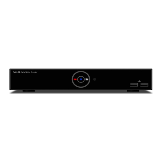
Package Contents The device package contents consist of the following: Note Please check all components involved. Table 1-1 Package contents Name Name SATA cable DC Power Adapter & Power cord SATA power cable Mouse HDD fixing screw Quick guide Program CD Part Description Each part is listed in the below: Figure 1-1 Name and Connection of each front section... - Page 9 8ch DVR 7 8 9 16ch DVR Figure 1-2 Name and Connection of each rear section of 4ch, 8ch, and 16ch DVR Table 1-3 Name and Function of each rear section of 4ch, 8ch, and 16ch DVR Name Function Audio In Camera audio input port Video In Camera video input port...
-
Page 10: Installation
Installation This chapter describes the way to install DVR. When installing a device, connect rear of the device with each port on the basis of below connection map. Figure 2-1 Connection map The device starts first like below sequences: 1 Installing HDD 2 Connecting with an exterior device 3 Starting a system 4 Setting an earlier stage... -
Page 11: Installing Hdd
Installing HDD How to install HDD in the device: Withdraw the mains plug before installing HDD to reduce the risk of injury or electrical shock, or device malfunction. Attention Make sure to check the compatibility of HDD with the device. 1 Always switch off and unplug the unit. - Page 12 6 Connect a monitor with VGA or HD output port. 7 Connect a network port. 8 Connect an alarm and RS485 devices. 9 Connect USB port in front section of the unit with a mouse. 10 Supply the main power after completion. Before connection, match socket with adapter pins.
-
Page 13: Starting System
Starting System Power supply begins with system operation as follows: 1 Switching on initialize with below icons in order. Note Installing new HDD might take more initialize time. 2 With buzzer sounds, the start screen is presented. 3 In Log in screen, enter the ID, Password and press OK. Default ID/Password is admin/admin. -
Page 14: Account
2.4.1 Account How to set Account of Easy Installation: 1 Click the keyboard icon to set ID and Password users want. 2 With keyboard UI, set the ID and Password, and press OK. 3 Press the Save button to save newly set ID and Password. 4 Press Next button to end Account setting and move the next setting phase. -
Page 15: System
2.4.2 System How to set the system of Easy Installation: 1 Set each item in System setting screen. Language: Select system language. Device Name: Enter the device name. Keyboard ID: To identify device usages in controlling DVR with RS485 through a keyboard Selecting the device ID. -
Page 16: Network
2.4.3 Network How to set the network of Easy Installation: 1 Set each item in Network setting screen. WAN Port: Select whether to use static IP or dynamic IP. IP Address, Subnet Mask, Gateway, DNS, and Port: As for dynamic IP, enter information in each space. -
Page 17: Time/Date
2.4.4 Time/Date How to set the time/date of Easy Installation: 1 Set each item in Time/Date setting screen. Network Time Sync: Select network for synchronizing with time server. System Time: Not for synchronizing with network time server, set the device time; otherwise (applying for Daylight saving time), select DST. -
Page 18: Screen Configuration
Live Screen Configuration UI screen is configured like below figure. Figure 3-1 UI Screen Configuration Table 3-1 Items and Description of UI Screen Configuration Item Description Setting menu Setting menu is located in the corner of upper screen. See “0 Setup ” to display detailed information about the setting menu. -
Page 19: Icons In Live Screen
Icons in Live screen Each icon in the live screen displays a present setting status or a function. UI screen consists of like below. Chosen live screen is marked as a blue frame; mouse-located live screen is marked Note as yellow one. Figure 3-2 Live screen icon Table 3-2 Live screen icon and its description Icon... -
Page 20: Live Launcher Menu
Live Launcher menu This chapter describes Launcher menu in the bottom of the screen. Figure 3-3 Launcher menu Table 3-3 Launcher menu Item and Description Item Description Login/Logout status and logged in ID Date & Time Displaying present date and time Displaying HDD capacity in use Moving to previous/next partition screen Displaying live screen in order set (toggle) -
Page 21: Backup
3.2.1 Backup The device provides a back-up function of live screen. Figure 3-4 Backup Table 3-4 Backup Item and Description Item Description Select CH Selecting a channel users want to back-up Select All/ Select or clear all channels. Unselect All Start Setting back-up start time (Bookmark: bookmark list). -
Page 22: Quick Menu
Quick menu This chapter depicts Quick menu when users click the right button of the mouse in live screen. Figure 3-5 Quick menu Table 3-5 Quick menu Item and Description Item Description Screen Mode Selecting the partition mode of live screen (Full, 2X2, 3X3, and 4x4). Zoom in Magnifying selected live screen (Zoom out, 2 times, 4 times, and 8 times). - Page 23 PTZ Control menu can be displayed if relevant channel’s protocol is set in DEVICE > Note PTZ in the upper live screen. Figure 3-6 Quick menu > PTZ Control Table 3-6 Quick menu > PTZ Control Item and Description Item Description Moving images with direction buttons Moving images with PTZ ball...
-
Page 24: Status > System Log
In PTZ Control screen, clicking the right button of the mouse displays Quick menu. Figure 3-7 PTZ Control Quick menu Table 3-7 PTZ Control Item and Description in Quick menu Item Description Preset Saving specific positions of the camera, at most 255 settings Tour Moving toward set routes, with assembling many groups, at most 255 settings Exit... -
Page 25: Status > Event
Table 3-8 Status of Quick menu > System log Item and Description Item Description Start Setting starting time of system log to search Setting ending time of system log to search Log Type Selecting log types (Network, Record, Setup, Disk, Backup, and System) Select All Selecting or clearing all log types (toggle). - Page 26 Figure 3-10 Status > Record in Quick menu Table 3-10 Status > Record Item and Description in Quick menu Item Description Record time Marking recorded period Record list Displaying the record setting status Cancel Completing the status screen...
-
Page 27: Setup Menu
Setup menu This chapter describes Setup menu in the upper side of the screen. Figure 4-1 Setup menu Selecting the menu opens the setting screen. Setup screen is available to click Setup in Quick menu by clicking the right button of Note the mouse. - Page 28 Setup menu includes: Table 4-2 Setup menu tree 1st Level 2nd Level 3th Level System System F/W Upgrade Time/Date Time/Date Holiday SYSTEM Account User Export/Import Configuration Factory Default Basic Basic Audio In CAMERA Advanced Advanced Display Display Sequence Layout DEVICE Disk Setup Serial Device...
-
Page 29: General Buttons In Setup Menu
1st Level 2nd Level 3th Level DVRNS/Dashboard DVRNS/DDNS DDNS E-Mail E-Mail General buttons in Setup menu This section depicts General buttons in Setup menu. Figure 4-3 General buttons in Setup menu Table 4-3 Item and Description of General buttons in Setup menu Item Description Default... -
Page 30: System
SYSTEM In SYSTEM, basic system environment is set. 4.2.1 System Set and upgrade the basic items of the system. System > System Set the basic items in the System. Figure 4-4 SYSTEM > System > System Table 4-4 SYSTEM > System > System Item and Description Name Function Language... - Page 31 System > F/W Upgrade Set the upgraded items of the system. Figure 4-5 SYSTEM > System > F/W Upgrade Table 4-5 SYSTEM > System > F/W Upgrade Item and Description Name Function Current Version Displaying the present tool version. Device Connect USB memory that has files to upgrade to the USB port, select files to upgrade.
-
Page 32: Time/Date
4.2.2 Time/Date Set the date, time, and holidays of the system. Time/Date > Time/Date Set the date, time, and holidays of the system. Figure 4-6 SYSTEM > Time/Date > Time/Date Table 4-6 SYSTEM > Time/Date > Time/Date Item and Description Name Function System Time... - Page 33 Set holidays of the system. Figure 4-7 SYSTEM > Time/Date > Holiday Table 4-7 SYSTEM > Time/Date > Holiday Item and Description Name Function Year Select years to set holidays. Delete selected holidays. Add Holiday Add holidays. List Display added holiday lists.
- Page 34 Clicking Add Holiday displays holiday addition screen like below. Figure 4-8 SYSTEM > Time/Date > Holiday > Add Holiday Table 4-8 SYSTEM > Time/Date > Holiday > Add Holiday Item and Description Name Function Name Enter the holiday name. Date Display chosen date.
-
Page 35: Account > User
4.2.3 Account > User Set the user’s account of the system. Figure 4-9 SYSTEM > Account > User Table 4-9 SYSTEM > Account > User Item and Description Name Function Add Group Add users’ group. Add User Add users. Group List Display a total group list. - Page 36 Press Add Group button, then Add Group screen displays. Figure 4-10 SYSTEM > Account > User > Add Group Table 4-10 SYSTEM > Account > User > Add Group Item and Description Name Function Name Enter the group name. PERMISSION Select items to permit access.
-
Page 37: Configuration (Config)
4.2.4 Configuration (Config) Set Export/Import and Factory Default of the system. Config > Export/Import Through a save medium, users may apply information set to other devices identically. Figure 4-12 SYSTEM > Config > Export/Import Table 4-12 SYSTEM > Config > Export/Import Item and Description Name Function Device... - Page 38 Config > Factory Default Default the setting value of the device. Figure 4-13 SYSTEM > Config > Factory Default Table 4-13 SYSTEM > Config > Factory Default Item and Description Name Function Select All Select/deselect all items to be defaulted. /Unselect All Default Item Select/deselect related items to be defaulted.
-
Page 39: Camera
CAMERA In CAMERA section, set the camera to be connected with the device. 4.3.1 Basic Set the fundamental functions of camera and audio. Basic > Basic Set the basic items of camera by channels. Figure 4-14 CAMERA > Basic > Basic Table 4-14 CAMERA >... - Page 40 Press Copy Covert Setup button, then Copy Covert Setup screen displays. Figure 4-15 CAMERA > Basic > Basic > Copy Covert Setup Table 4-15 CAMERA > Basic > Basic > Copy Covert Setup Item and Description Name Function From Select a channel converted setting. Select a channel to be copied.
- Page 41 Basic > Audio In How to set audio of camera across channels Figure 4-16 CAMERA >Basic > Audio In Table 4-16 CAMERA > Basic > Audio In Item and Description Name Function Display channels of audio Select/deselect whether to use audio. Assign Select channels to be assigned audio.
-
Page 42: Advanced
4.3.2 Advanced As advanced function of camera, users can set privacy. Figure 4-17 CAMERA > Advanced Table 4-17 CAMERA > Advanced Item and Description Name Function Display channels. Video Set brightness, contrast, and color of the camera. Privacy Mask Set the privacy field; display field numbers set in parenthesis (at most 4 setting available). - Page 43 Locate the mouse in the Privacy Mask field, and then click Editing Icon ( ) in the right corner, then Privacy Mask screen displays. Figure 4-18 CAMERA > Advanced > Privacy Mask Table 4-18 CAMERA > Advanced > Privacy Mask Item and Description Name Function Select channels to set privacy field.
-
Page 44: Device
DEVICE In DEVICE, set the device to connect with the unit. 4.4.1 Display Set matters related to a display device and live screen. Display > Display Set the display device. Figure 4-19 DEVICE > Display > Display Table 4-19 DEVICE > Display > Display Item and Description Name Function HD Output/VGA... - Page 45 Display > OSD Set the OSD of the display device. Figure 4-20 DEVICE > Display > OSD Table 4-20 DEVICE > Display > OSD Item and Description Name Function Camera Name Select the way to display camera in live screen (Off, CH+Title, CH). Live Bar Select the way to display the live bar (Always On, Auto Hide).
- Page 46 Display > Sequence How to set the play sequence of live screen Figure 4-21 DEVICE > Display > Sequence Table 4-21 DEVICE > Display > Sequence Item and Description Name Function Quad Sequence Set to convert automatically as 4-partition screen on the time basis. Division Select screen partition mode to be marked in the below table (All, Full, and Quad).
- Page 47 Clicking Add Sequence displays Add Sequence screen. Figure 4-22 DEVICE > Display > Sequence > Add Sequence Table 4-22 DEVICE > Display > Sequence > Add Sequence Item and Description Name Function Dwell Time Select time to play (3 sec, 5 sec, 10 sec, 15 sec, and 30 sec). Division Select the partition screen to play (Full, Quad).
- Page 48 Display > Layout Users can set the partition mode in live screen. Figure 4-23 DEVICE > Display > Layout Table 4-23 DEVICE > Display > Layout Item and Description Name Function Division Select the types of screen partitions (all, 2X2, 3X3, 2+8, 4X4, 5X5, 6X5, and 6X6).
- Page 49 Clicking editing icon in CH List displays Edit Division screen. Figure 4-24 DEVICE > Display > Layout > Edit Division Clicking Add Division displays Add Division screen. Figure 4-25 DEVICE > Display > Layout > Add Division Table 4-24 DEVICE > Display > Layout > Edit/Add Division Item and Description Name Function Division...
-
Page 50: Disk > Setup
4.4.2 Disk > Setup The way to set the disk Figure 4-26 DEVICE > Disk > Setup Table 4-25 DEVICE > Disk > Setup Item and Description Name Function Refresh disk information. Disk Info Display the basic disk information in disc list. Model: disk model name Free: disk capacity to save Size (Capacity): total disk capacity... -
Page 51: Ptz > Ptz
Name Function Auto Delete Select/deselect to use the function to delete saved data automatically (1- 365 days). 4.4.3 PTZ > PTZ To use PTZ Function of the device, users need to match ID, protocol, and speed with each camera. Figure 4-27 DEVICE > PTZ > PTZ Table 4-26 DEVICE >... -
Page 52: Serial Device > Serial Device
4.4.4 Serial Device > Serial Device Users need to set Serial Device to connect PTZ camera, USB device with the unit. Figure 4-28 DEVICE > Serial Device > Serial Device Table 4-27 DEVICE > Serial Device > Serial Device Item and Description Name Function USB (to Serial) -
Page 53: Text > Text
4.4.5 TEXT > TEXT Set the input device such as ATM or POS, etc. Figure 4-29 DEVICE > TEXT > TEXT Table 4-28 DEVICE > TEXT > TEXT Item and Description Name Function Select/deselect whether to use text function. Select camera channels to connect with the text input device. Protocol Select protocol to correspond with the text input device. - Page 54 Press Copy to TEXT Setup button, then Copy to TEXT Setup screen displays. Figure 4-30 DEVICE > TEXT > TEXT > Copy to TEXT Setup Table 4-29 ICE > TEXT > TEXT > Copy to TEXT Setup Item and Description Name Function From...
-
Page 55: Record
RECORD In RECORD, users may set matters related to recording. 4.5.1 Schedule > Schedule Recording types can be set across channels and time. Figure 4-31 RECORD > Schedule > Schedule Table 4-30 RECORD > Schedule > Schedule Item and Description Name Function Select channels to set schedules. - Page 56 The function of each scheduling type involves: Table 4-31 Function of each scheduling type Color Scheduling type Function None Do not record. Continuous Record on consecutive mode when time set. Motion Record on event recording mode when motion sensitive event occurs. Alarm Record on event recording mode when alarm occurs.
- Page 57 7 Copy Schedule Setup screen displays. 8 Select channels to be copied. 9 Select channels to apply copied content. 10 Copy the schedule by pressing Apply. 11 Press Save to save the schedule.
-
Page 58: Stream
4.5.2 Stream To set the image resolution when event occurs across channels or general recording is in process. Stream > Main Stream To set the image quality and resolution of Main Stream Figure 4-32 RECORD > Stream > Main Stream Table 4-32 RECORD >... - Page 59 Clicking Copy Stream Setup opens Copy Stream Setup. Figure 4-33 RECORD > Stream > Main Stream > Copy Stream Setup Table 4-33 RECORD > Stream > Main Stream > Copy Stream Setup Item and Description Name Function From Select the channel set. Select the device to be copied.
- Page 60 Stream > Second Stream To set the image quality and resolution of Second Stream Figure 4-34 RECORD > Stream > Second Stream Table 4-34 RECORD > Stream > Second Stream Item and Description Name Function Display channels. Resolution Set the resolution of video clips (640X480). Frame Rate Select recording FPS (1-30).
- Page 61 Stream > Panic How to set immediate recording Figure 4-35 RECORD > Stream > Panic Table 4-35 RECORD > Stream > Panic Item and Description Name Function Panic Record Select/deselect to use immediate recording function. Display channels. Resolution Set the resolution of video clips (1080P, 720P, 960H). Frame rate Select recording FPS (1-30).
-
Page 62: Event
EVENT In EVENT, users may set each event of the device. 4.6.1 System/Disk To set the system and disk event System/Disk > System To set the system event of the device Figure 4-36 Event > System/Disk > System Table 4-36 Event > System/Disk > System Item and Description Name Function System Restart... - Page 63 System/Disk > Disk To set disk event Figure 4-37 Event > System/Disk > Disk Table 4-37 Event > System/Disk > Disk Item and Description Name Function Disk Unplugged Select/deselect whether to use disk unplugged event Beep Select/deselect whether to use buzzer sound in case of event. Alarm out Select to end alarm time (null, Relay1-Keep, 5 sec, 10 sec, 20 sec, 30 sec, 1 min, 10 min, 30 min, and 1 hour).
-
Page 64: Alarm In
4.6.2 Alarm In To set sensor alarms and schedule Alarm In > Setup To set sensor alarms Figure 4-38 Event > Alarm In > Setup Table 4-38 Event > Alarm In > Setup Item and Description Name Function Sensor Display sensor numbers. Select/deselect whether to use alarm in the sensor. - Page 65 Placing your mouse on Alarm, Group Rec, Noti., Preset and clicking editing Icon( ) in right corner displays Event : Alarm screen. Figure 4-39 Event > Alarm In > Setup > Event : Alarm Table 4-39 Event > Alarm In > Setup > Event : Alarm Item and Description Name Function Alarm-out...
- Page 66 Alarm In > Schedule To schedule recording time when alarm occurs across device sensors Figure 4-40 Event > Alarm In > Schedule Table 4-40 Event > Alarm In > Schedule Item and Description Name Function Sensor Select the sensor to set the schedule. Schedule Type Select the types of schedules.
-
Page 67: Motion
4.6.3 Motion To set and schedule motions across channels Motion > Setup To set motions across channels Figure 4-41 Event > Motion > Setup Table 4-41 Event > Motion > Setup Item and Description Name Function Display channels. Select/deselect whether to use motion function in the channel. Area Display the motion area. - Page 68 icon( ) in right corner displays Event : Alarm screen. For more information about Event : Motion screen, see section “4.6.2 Alarm In > Setup in Alarm In.” Motion > Schedule To schedule record time when the motion sensor detects across channels Figure 4-42 Event >...
-
Page 69: Video Loss > Setup
4.6.4 Video Loss > Setup To set Video Loss across channels Figure 4-43 Event > Video Loss > Setup Table 4-43 Event > Video Loss > Setup Item and Description Name Function Display channels. Select/deselect whether to use Video Loss in the channel. Beep Select use time of buzzer sound (null, 5 sec, 10 sec, 20 sec, 30 sec, 1 min, 10 min, 30 min, and 1 hour). -
Page 70: Notification
4.6.5 Notification To set and schedule periodical alarms Notification > Periodic To set periodical alarms Figure 4-44 EVENT > Notification > Periodic Table 4-44 EVENT > Notification > Periodic Item and Description Name Function Periodic Select/deselect whether to use periodical alarms Notification Summary Send the save or event information. - Page 71 Notification > Schedule To schedule periodical alarms Figure 4-45 EVENT > Notification > Schedule Table 4-45 EVENT > Notification > Schedule Item and Description Name Function Schedule Type Select the types of schedules. Selection Schedule Table Display the schedule users set. Drag Field Display the area dragged with a mouse.
-
Page 72: Network
NETWORK In NETWORK, users may set the network environment. 4.7.1 Basic > WAN Port To set the network environment Figure 4-46 NETWORK > Basic > WAN Port Table 4-46 NETWORK > Basic > WAN Port Item and Description Name Function Static IP Check if you use static IP. -
Page 73: Dvrns/Ddns
4.7.2 DVRNS/DDNS To set DVRNS/DDNS DVRNS/DDNS > DVRNS/Dashboard To register DVRNS/Dashboard account Figure 4-47 NETWORK > DVRNS/DDNS > DVRNS/Dashboard Table 4-47 NETWORK > DVRNS/DDNS > DVRNS/Dashboard Item and Description Name Function DVRNS Register DVRNS account ID: Enter DVRNS ID (default: MAC address of the unit) Password: Enter DVRNS password Register: Register DVRNS account Dashboard... - Page 74 DVRNS/DDNS > DDNS To set DDNS site for remote users to access in networking Figure 4-48 NETWORK > DVRNS/DDNS > DDNS Table 4-48 NETWORK > DVRNS/DDNS > DDNS Item and Description Name Function DDNS Site Select DDNS site Host Name Enter the host name.
-
Page 75: E-Mail
4.7.3 E-Mail To set email server to send email on the occasion of event Figure 4-49 NETWORK > E-Mail > E-Mail Table 4-49 NETWORK > E-Mail > E-Mail Item and Description Name Function Server Type Select SMTP server. gmail.com hotmail.com aol.com naver.com daum.com... -
Page 76: Search/Play
Search/Play This chapter describes Live Launcher search and play menu in the below screen bar. Figure 5-1 Live Launcher Search, Play menu Table 5-1 Item and Description of Live Launcher Search, Play menu Item Description Searching recording data (time, event, and thumbnail). Playing recorded data Search This function searches recorded data as Time, Event, Thumbnail, and Text. - Page 77 Figure 5-3 Search: Event Table 5-3 Search: Event Item and Description Item Description Select CH Select channels to search Select All Select/deselect all channels. /Unselect All Start Setting starting time to search Setting ending time to search EVENT TYPE Selecting the types of event (immediate recording, motion, Alarm-In, Video Loss, and bookmark).
- Page 78 Figure 5-4 Search: Thumbnail Table 5-4 Search: Thumbnail Item and Description Item Description Calendar Selecting dates to search Selecting channels to search Time Selecting time to search Interval Setting time interval for searching images Time Playing or stopping videos searched Lapse/Pause Cancel Ending search screen...
- Page 79 Figure 5-5 Search: Text Table 5-5 Search: Text Item and Description Item Description Select CH Select channels to search Select All Select/deselect all channels. /Unselect All Start Setting starting time to search Setting ending time to search Keyword Entering keyword to search Case Sensitive Searching items in case-sensitive Whole Word...
-
Page 80: Playback
Playback To play recorded data Figure 5-6 Playback Launcher Table 5-6 Playback Launcher Item and Description Item Description Displaying present play status Date and Time Displaying date and time of playing videos Moving to the first section of the video Playing the videos with multiplied speed in reverse (2~64x). -
Page 81: Webviewer
Webviewer This chapter describes webviewer for monitoring videos through a PC in remote mode. How to monitor with webviewer Enter IP address of a recorder in Internet browser. Enter ID and Password, and then click the button. Viewer: playing DVR Live images Setup: setting menu in similar ways with DVR connected monitor. - Page 82 Live images may be monitored. In case of selecting Setup Users can set the menu in similar ways with DVR connected monitor. Figure 6-1 Setup screen...
-
Page 83: Products Specifications
Products Specifications Channel 16CH Operation Embedded (Linux) Embedded (Linux) Embedded (Linux) System DISPLAY 1 VGA, 1 HD Output, 1 1 VGA, 1 HD Output, 1 Video Output VGA, HD Output BNC(Spot, CVBS) BNC(Spot, CVBS) 1920x1080, 1280x720, 1920x1080, 1280x720, 1920x1080, 1280x720, Resolution 1024x768 1024x768... - Page 84 Network Port 1 (1Gbps) 1 (1Gbps) 1 (1Gbps) Maximum Unlimited (Guarantee Unlimited (Guarantee Unlimited (Guarantee Network 72Mbps, support 144Mbps, support 288Mbps, support Throughput Bandwidth control) Bandwidth control) Bandwidth control) for Output RS485 1 Terminal Block 1 Terminal Block 1 Terminal Block 2 (USB2.0) 2 (USB2.0, USB3.0) 2 (USB2.0, USB3.0)
Need help?
Do you have a question about the AHDVR PROFESSIONAL Series and is the answer not in the manual?
Questions and answers