Toro 30344 Operator's Manual
Traction unit
Hide thumbs
Also See for 30344:
- Operator's manual (60 pages) ,
- Operator's manual (56 pages) ,
- Operator's manual (60 pages)

Subscribe to Our Youtube Channel
Related Manuals for Toro 30344


Summary of Contents for Toro 30344
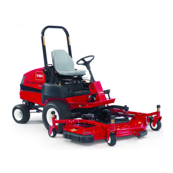
- Page 1 Form No. 3405-487 Rev A Groundsmaster ® 3280-D Traction Unit Model No. 30344—Serial No. 316000001 and Up Model No. 30345—Serial No. 316000001 and Up *3405-487* A Register at www.Toro.com. Original Instructions (EN)
- Page 2 California to cause cancer, birth defects, 1. Model and serial number location and other reproductive harm. Model No. Genuine Toro spark arresters are approved by the USDA Forestry Service. Serial No. It is a violation of California Public Resource Code...
-
Page 3: Table Of Contents
Contents Greasing the Bearings and Bushings ......38 Engine Maintenance ..........40 Servicing the Air Cleaner .........40 Safety ................4 Servicing the Engine Oil..........41 General Safety............4 Fuel System Maintenance ...........42 Sound Power Level ..........4 Servicing the Water Separator ........42 Sound Pressure Level..........4 Cleaning the Fuel Tank..........43 Vibration Level ............ -
Page 4: Safety
Sound Power Level Safety This unit has a guaranteed sound power level of 105 dBA, This machine has been designed in accordance with EN ISO which includes an Uncertainty Value (K) of 1 dBA. 5395:2013 when equipped with the proper CE kit (refer to the Declaration of Conformity) and rear weight;... -
Page 5: Safety And Instructional Decals
Safety and Instructional Decals Safety decals and instructions are easily visible to the operator and are located near any area of potential danger. Replace any decal that is damaged or lost. 82-8940 1. Locked 3. Unlocked 2. Tilt steering 92–1582 Battery Symbols Some or all of these symbols are on your battery. - Page 6 93-6686 1. Hydraulic fluid 2. Read the Operator's Manual. 93-6697 (Model 30345) 1. Read the Operator's 2. Add SAE 80w-90 (API Manual. GL-5) oil every 50 hours. 93-7272 1. Cutting/dismemberment hazard; fan—stay away from moving parts. 93-7834 1. No step 4.
- Page 7 105-7179 1. Read the Operator's 2. Parking brake Manual. 108-2073 106-5976 1. Warning—there is no rollover protection when the roll bar is down. 1. Engine coolant under 3. Warning—do not touch the 2. To avoid injury or death from a rollover accident, keep the pressure hot surface.
- Page 8 119-4840 1. PTO—On 3. Lower deck 5. Engine—stop 7. Engine—start 2. PTO—Off 4. Raise deck 6. Engine—run 133–6377...
- Page 9 133–6375 1. Warning—read the Operator's Manual, all operators should 5. Cutting/dismemberment hazard of hands or feet, mower be trained before operating the machine. blade—stay away from moving parts. 2. Warning—engage the parking brake, and remove the ignition 6. Tipping hazard—when driving down slopes, lower the cutting key before leaving the machine.
-
Page 10: Setup
Setup Loose Parts Use the chart below to verify that all parts have been shipped. Procedure Description Qty. Steering wheel Install the steering wheel. Cover Handle Install the hood handle. Screws Seat—Model No. 30398 (optional kit) Mechanical seat suspension kit—Model Install the seat. - Page 11 Procedure Description Qty. Operator's Manual Engine Operator's Manual Parts Catalog Operator Training Material Pre-delivery Inspection Sheet Read the manuals and watch the Certificate of compliance training materials before operating the Certificate of Quality machine. Use the listed hardware for Roll pin the installation of attachments.
-
Page 12: Installing The Steering Wheel
Installing the Steering Wheel Installing the Hood Handle Parts needed for this procedure: Parts needed for this procedure: Steering wheel Handle Cover Screws Procedure Procedure 1. Remove the steering wheel from the shipping skid 1. Remove and discard the 2 screws and nuts securing the (Figure hood cable bracket and to the underside of the hood (Figure... -
Page 13: Installing The Seat
Installing the Seat Parts needed for this procedure: Seat—Model No. 30398 (optional kit) Mechanical seat suspension kit—Model No. 30312 (optional kit) or Pneumatic seat suspension kit—Model Figure 6 No. 30313 (optional kit) 1. Seat-belt latch Procedure 1. Assemble end of each seat belt halves to the holes in the back of the seat with 2 bolts (7/16 x 1 inch), flat The Groundsmaster 3280-D is shipped without the seat washers (7/16 inch), and lock washers (7/16 inch) -
Page 14: Adjusting The Rops
2. Raise the roll bar to the upright position and install the 2 pins and secure them with the hairpin cotters(Figure Note: The roll bar is an integral and effective safety device. Keep the roll bar in the raised and locked position. -
Page 15: Charging The Battery
2. When the battery is charged, disconnect the charger from the electrical outlet and then disconnect the charger from the battery posts. Note: Incomplete charging may result in gassing of the battery and the overflow of battery acid, causing corrosive damage to the machine. WARNING CALIFORNIA Figure 9... -
Page 16: Checking The Fluid Levels
Checking the Air Pressure in the Tires No Parts Required Procedure Figure 11 Tire air pressure specification (front and rear tires): 138 kPa (20 psi). 1. Positive (+) 3. Front of the machine 2. Negative (-) Check the air pressure in the front and rear tires before the engine is first started. -
Page 17: Installing The Lift-Lock Lever
Installing the Lift-Lock Lever Parts needed for this procedure: Lift-lock lever Flat washer Spring washer Figure 14 Spacer 1. Screw 5. Flat washer 2. L lever 6. Decal Screw (1/4 x 1 inch) LOCK 3. Spring washer 7. Locknut Flange locknut (1/4 inch) 4. - Page 18 Note: If the casters of the mower deck float above the 4. At the front of the lift manifold, remove the cap from ground, the hydraulic pressure of the weight transfer the weight-transfer spool (Figure 16). valve is set at too high. 5.
-
Page 19: Installing The Rear Weights
Use the table that follows to determine the combinations of additional weight required. Order parts from your local Authorized Toro Distributor. Note: Before installing any third-party kits, contact your local Authorized Toro Distributor. Weight Table (machines with 98 Kg (215 lb) of factory installed rear weight and machines with... -
Page 20: Reading The Manuals And Viewing The Training Materials
Procedure 1. Read the manuals. 2. View the operator training materials. Reading the Manuals and 3. Save the roll pin, bolts (5/16 x 1-3/4 inches), and locknuts (5/16 inch) to secure the universal shaft to Viewing the Training Materials an implement. 4. -
Page 21: Product Overview
Product Overview Figure 17 1. Steering wheel 3. Brakes 5. Hood/engine compartment 2. Traction pedal 4. Cutting unit 6. ROPS (Rollover Protection System) Controls Brakes Figure 19 1. Left-brake pedal 3. Lock arm 2. Right-brake pedal Service Brakes g035076 The left and right brake pedals (Figure 18) are connected Figure 18... -
Page 22: Traction Pedal
Tilt-Steering Control brake pedals together. Always lock the brakes together when transporting the machine (Figure 19). The tilt-steering control is a lever on the right side of the steering column (Figure 21). Pull the lever rearward to adjust Parking Brake the steering wheel to the desired fore or aft operating position and push the lever forward to lock the adjustment. -
Page 23: Key Switch
Figure 23 1. Fuel gauge Figure 22 Key Switch 1. PTO switch 7. Throttle lever 2. Lift-lock lever (optional) 8. 12V Power point The key switch has 3 positions: O , and REHEAT 3. Lift switch 9. Hour meter (Figure 22). -
Page 24: Specifications
Contact your Authorized Service Dealer or service the machine. Local regulations may restrict the Distributor or go to www.Toro.com for a list of all approved age of the operator. The owner is responsible for training attachments and accessories. -
Page 25: Accessing The Machine
• • Inspect the area where you will use the machine and If you spill fuel on your clothing, change your clothing remove all objects that the machine could potentially immediately. throw. • Fill the fuel tank until the fuel level is 25 mm (1 inch) •... -
Page 26: Checking The Machine Daily
Closing the Hood Checking the Machine Daily Check the following machine systems each day before operating the machine: • Air Cleaner Indicator; refer to Checking the Air Cleaner Indicator (page 40) • Engine oil; refer to Checking the Engine-Oil Level (page •... -
Page 27: Checking The Interlock System
Checking the Interlock System Adding Fuel to the Machine Service Interval: Before each use or daily Fuel tank capacity: 72 L (12.8 US gallons) The purpose of the safety interlock system is to prevent the Fuel Specification: engine from cranking or starting unless the traction pedal Use only clean, fresh diesel fuel or biodiesel fuels with low is in neutral and the PTO switch is in the O position. -
Page 28: Adjusting The Rollover Protection System (Rops)
Figure 29 Figure 30 Note: If possible, fill the fuel tank after each use; this minimizes possible buildup of condensation inside the fuel Raising the ROPS tank. Adjusting the Rollover Protection System (ROPS) Lowering the ROPS Important: Lower the roll bar only when absolutely necessary. -
Page 29: Adjusting The Tilt-Steering Control
Adjusting the Tilt-Steering During Operation Control General Safety 1. Remove the knob from the parking brake and the screws from the steering-column cover (Figure 32). • The owner/user can prevent and is responsible for accidents that may cause injuries to himself/herself and others and for damage to property. -
Page 30: Rollover Protection System (Rops) Safety
Do not use the machine as a towing vehicle. • Use extra care while operating the machine with • Use accessories and attachments approved by The Toro® attachments; they can affect the stability of the machine. Company only. Starting and Shutting Off the... -
Page 31: Resetting The Pto Function
Bleeding the Fuel-Injection that all parts are properly operating. Turn the power-steering wheel to the left and right to check Pump the steering response. Then shut the engine off, check the fluid levels, and check for oil leaks, loose 1. Park the machine on a level surface. parts, and any other malfunctions. -
Page 32: Operating Tips
In an emergency, the machine can be pushed or towed for a brakes. You can use the brakes to assist in turning the very short distance. However, Toro does not recommend this machine; however, use them carefully, especially on soft as standard procedure. -
Page 33: Hauling The Machine
g035503 Figure 35 Figure 36 1. Hydraulic pump 3. Front of the machine 2. Control knob (bypass 1. Tie-down loops valve) 3. Rotate the control knob 3 turns counterclockwise (Figure 35). Important: Do not rotate the control knob more that 3 turns. Closing the Bypass Valve of the Hydraulic Pump To Operate the Machine... -
Page 34: Maintenance
Maintenance Note: Looking for an Electrical Schematic or Hydraulic Schematic for your machine? Download a free copy of the schematic by visiting www.Toro.com and searching for your machine from the Manuals link on the home page. Recommended Maintenance Schedule(s) Maintenance Service... -
Page 35: Daily Maintenance Checklist
Daily Maintenance Checklist Duplicate this page for routine use. Maintenance Check Item For the week of: Mon. Tues. Wed. Thurs. Fri. Sat. Sun. Check Safety Interlock Operation Make sure the ROPS is fully raised and locked in position Check Grass Deflector in Down Position Check Brake Operation Check Fuel Level... -
Page 36: Premaintenance Procedures
3. Ensure that the PTO switch is in the O position. • Use only genuine Toro replacement parts and accessories. 4. Set the parking brake. Replacement parts and accessories made by other manufacturers could be dangerous, and such use could 5. -
Page 37: Hydraulic Pump Access
Hydraulic Pump Access 4. Assemble the seat plate (Figure 38) to the carriage bolts with the 2 flange locknuts (3/8 inch) that you removed in step Removing the Seat and Seat Plate (page 37). Removing the Seat and Seat Plate 5. -
Page 38: Lubrication
Lubrication Greasing the Bearings and Bushings Service Interval: Every 50 hours—Grease the bearings and bushings. When operating the machine in extremely dusty and dirty conditions, lubricate the bearings and bushings daily. Every 400 hours/Yearly (whichever comes Figure 40 first)—Grease the rear-axle bearings Grease specification: No. - Page 39 Figure 46 Figure 43 • Cylinder-rod ends (2) (Figure • Steering pivots (2) (Figure • Steering-plate bushings (Figure • Axle-pivot pin (Figure Note: Bearing life can be negatively affected by improper wash-down procedures. Do not wash down the machine when it is still hot and avoid directing high-pressure or high-volume spray at the bearings.
-
Page 40: Engine Maintenance
Engine Maintenance Important: Be sure that the cover is seated correctly and seals with the air-cleaner body. Note: Determine the left and right sides of the machine 1. Replace the primary air-cleaner element(Figure 48). from the normal operating position. Servicing the Air Cleaner Checking the Air Cleaner Indicator Service Interval: Before each use or daily •... -
Page 41: Servicing The Engine Oil
– Preferred oil: SAE 15W-40 (above 0°F) – Alternate oil: SAE 10W-30 or 5W-30 (all temperatures) Note: Toro Premium Engine Oil is available from your distributor in either 15W-40 or 10W-30 viscosity. See the parts catalog for part numbers. Figure 51 Checking the Engine-Oil Level 1. -
Page 42: Fuel System Maintenance
Changing the Engine Oil And Filter Fuel System Service Interval: After the first 50 hours Maintenance Every 150 hours Note: Refer to Adding Fuel to the Machine (page 27) If possible, run engine just before changing oil because warm proper the fuel recommendations. oil flows better and carries more contaminants than cold oil. -
Page 43: Cleaning The Fuel Tank
Cleaning the Fuel Tank Electrical System Maintenance Service Interval: Every 400 hours/Yearly (whichever comes first)—Drain and clean the fuel tank Drain and clean tank if fuel system becomes contaminated or Electrical System Safety if you store the machine for an extended period of time. Use clean diesel fuel to flush out the tank. - Page 44 Checking the Battery Electrolyte • The battery cables must be tight on the terminals to provide good electrical contact. Service Interval: Every 50 hours • If corrosion occurs, perform the following: Monthly WARNING DANGER Incorrect battery cable routing could damage Battery electrolyte contains sulfuric acid which is a the machine and cables, causing sparks.
-
Page 45: Accessing The Fuse Block And Standard Control Module
Accessing the Fuse Block and Standard Control Module Removing the Control-Panel Plate 1. Remove the 4 thumb screws that secure the control-panel plate to the fuel tank (Figure 57). Figure 58 1. Tabs (side panel) 2. Slots (frame—console) 3. Align the slots in the top of the control-panel plate with the holes in the flange of the fuel tank (Figure 57). -
Page 46: Standard Control Module (Scm)
Standard Control Module • Power takeoff (PTO) operation • (SCM) Engine starting function • High temperature condition Important: The information presented below is and The SCM controls outputs features include the following: overview of the standard control module. Refer to the Service Manual for the machine for troubleshooting •... -
Page 47: Servicing The Wiring Harness
Drive System Maintenance Prevent corrosion of wiring terminals by applying Grafo 112X (Skin-over) grease, Toro Part No. 505-47, to the inside of all harness connectors whenever you replace the harness. Torquing the Wheel-Lug Nuts Important: Whenever working with the electrical... - Page 48 Changing the Rear Axle Lubricant (Model 30345 Only) Service Interval: Every 400 hours 1. Position the machine on a level surface. 2. Clean the areas around the 3 drain plugs (Figure 64). Note: 1 plug at each outboard-axle case and 1 plug at the center-axle housing.
-
Page 49: Maintaining The Bidirectional Clutch
6. Install the check plug into the clutch housing. 4. If the wheels toe-in or toe-out, align the wheels by performing the following: Changing the Bidirectional-Clutch • Adjusting Rear Wheel Toe-in (Model 30344) (page 50). Lubricant (Model 30345 Only) • Adjusting Rear Wheel Toe-in (Model 30345) (page Service Interval: Every 400 hours 50). -
Page 50: Torquing The Bolts For The Steering-Cylinder Mount (Model 30345 Only)
Adjusting Rear Wheel Toe-in (Model Torquing the Bolts for the 30344) Steering-Cylinder Mount 1. Loosen the jam nuts at both ends of the left and right (Model 30345 Only) tie rods. 2. Adjust both tie rods until center-to-center distance at... - Page 51 WARNING You must run the engine so that you can perform the final traction adjustment. Contact with hot or moving parts can result in personal injury. Keep your hands, feet, face, and other body parts away from the muffler, other hot parts of the engine, and other rotating parts.
-
Page 52: Adjusting Steering Stops (Model 30345 Only)
Adjusting Steering Stops (Model 30345 Only) The rear-axle-steering stops help prevent over-travel of the steering cylinder in case of impact on the rear wheels. Adjust the stops so that there is 0.23 cm (0.090 inch) clearance between the bolt head and the knuckle on the axle when you turn the steering wheel completely to the left or to the right. -
Page 53: Cooling System Maintenance
Checking the Cooling System Cooling System and Coolant Level Maintenance Service Interval: Before each use or daily Check the level of the coolant level before the engine is first Cooling System Safety started and daily thereafter. CAUTION WARNING Discharge of hot, pressurized coolant or touching a If the engine has been running, the radiator will be hot radiator and surrounding parts can cause severe pressurized and the coolant inside will be hot. -
Page 54: Checking The Hood Screen And Radiator For Debris
Checking the Hood Screen Brake Maintenance and Radiator for Debris Adjusting the Service Brakes Service Interval: Before each use or daily Check a the hood screen and radiator more frequently in Service Interval: After the first 10 hours extremely dusty and dirty conditions. After the first 50 hours To prevent the engine from overheating, keep the hood Every 50 hours... -
Page 55: Adjusting The Parking-Brake-Interlock Switch
Adjusting the 6. Press down on the parking-brake rod and push up the switch until the compressed length of the switch Parking-Brake-Interlock plunger is 0.7 mm (0.030 inches) (Figure 76, inset). Switch Note: This is the distance between the brake-rod paddle and the switch-plunger housing. -
Page 56: Belt Maintenance
Belt Maintenance Servicing the PTO Belt Checking the PTO Belt Tension Checking the Condition of the Service Interval: After the first 10 hours Alternator Belt After the first 50 hours Service Interval: Every 200 hours Every 200 hours Check alternator belt for wear or damage. 1. -
Page 57: Controls System Maintenance
Adjusting the Traction Pedal Controls System Maintenance Adjusting the Traction-Pedal Stop You can adjust the traction pedal for operator comfort or to Adjusting the PTO Clutch Gap reduce the maximum forward speed of the machine. 1. Move the traction pedal fully forward (Figure 80) . - Page 58 Adjusting the Traction Rod If more adjustment is required, adjust the traction rod (Figure 82) as follows: 1. Remove the bolt and nut securing traction rod end to the pedal. 2. Loosen the jam nut securing rod end to the traction (Figure 82).
-
Page 59: Hydraulic System Maintenance
(Available in 5 gallon pails or 55 gallon drums. See parts catalog or Toro distributor for part numbers.) Alternate fluids: If the Toro fluid is not available, you may use other petroleum-based Universal Tractor Hydraulic Fluids (UTHF) provided that its specifications fall within the listed range for all the following material properties and that it meets industry standards. - Page 60 Checking the Hydraulic System and Fluid Level Service Interval: Before each use or daily Check the level of the hydraulic fluid before the engine is first started and daily thereafter. Note: The transaxle housing acts as the reservoir for the hydraulic system.
-
Page 61: Storage
2. Clean the battery, terminals, and posts with a wire brush and baking-soda solution. 3. Coat the cable terminals and battery posts with Grafo 112X skin-over grease (Toro Part No. 505-47) or petroleum jelly to prevent corrosion. 4. If you plant to store the machine more than 30 days, remove the battery and charge it fully. -
Page 62: Preparing The Engine
Preparing the Engine 1. Change the engine oil and oil filter; refer to Changing the Engine Oil And Filter (page 42). 2. Start the engine and run it at idle speed for 2 minutes. 3. Shut off the engine. 4. Drain the fuel from the fuel tank, fuel lines, pump, filter, and separator. - Page 63 The Way Toro Uses Information Toro may use your personal information to process warranty claims, to contact you in the event of a product recall and for any other purpose which we tell you about. Toro may share your information with Toro's affiliates, dealers or other business partners in connection with any of these activities. We will not sell your personal information to any other company.
- Page 64 Countries Other than the United States or Canada Customers who have purchased Toro products exported from the United States or Canada should contact their Toro Distributor (Dealer) to obtain guarantee policies for your country, province, or state. If for any reason you are dissatisfied with your Distributor's service or have difficulty obtaining guarantee information, contact the Toro importer.
Need help?
Do you have a question about the 30344 and is the answer not in the manual?
Questions and answers