
Subscribe to Our Youtube Channel
Related Manuals for CleaverBrooks FLX Series


Summary of Contents for CleaverBrooks FLX Series
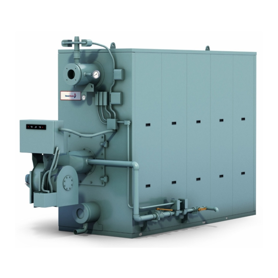
- Page 1 MODEL PACKAGED BOILER 12,500,000 to 25,000,000 BTU/hr Hot Water Fuel: Light Oil, Gas or Combination Manual Part No. 750-364 09/2013...
- Page 2 MODEL FLX PACKAGED BOILER Operation, Service, and Parts Manual 12,500,000 to 25,000,000 Btu/hr Fuel: Light Oil, Gas or Combination Cleaver-Brooks 2013 Please direct purchase orders for replacement manuals to your local Cleaver-Brooks authorized representative Manual Part No. 750-364 Revised 9/2013 Printed in U.S.A.
- Page 3 WARNING ! DANGER DO NOT OPERATE, SERVICE, OR REPAIR THIS EQUIPMENT UNLESS YOU FULLY UNDERSTAND ALL APPLICABLE SECTIONS OF THIS MANUAL. DO NOT ALLOW OTHERS TO OPERATE, SERVICE, OR REPAIR THIS EQUIPMENT UNLESS THEY FULLY UNDERSTAND ALL APPLICABLE SECTIONS OF THIS MANUAL. FAILURE TO FOLLOW ALL APPLICABLE WARNINGS AND INSTRUCTIONS MAY RESULT IN SEVERE PERSONAL INJURY OR DEATH.
-
Page 4: Table Of Contents
TABLE OF CONTENTS Chapter 1 General Description A. General ............... . 1-1 B. - Page 5 Chapter 5 Adjustment Procedures A. Burner Operating Controls ............5-1 B.
- Page 7 CHAPTER 1 GENERAL DESCRIPTION A. General ........1-1 B.
-
Page 8: General Description
The operator should be familiar with this manual in its the proper authorities having jurisdiction are to be consulted, entirety before attempting to place the unit into operation. permits obtained, etc. All boilers in the FLX series comply, when equipped with optional equipment, to Industrial Risk C. Construction Insurers (IRI), Factory Mutual (FM), or other insuring underwriters requirements. - Page 9 GENERAL DESCRIPTION Chapter 1 Auxiliary Low Water Cutoff (Optional): Breaks the circuit to stop burner operation if the water level in the boiler drops below the master low-water cutoff point. Safety Valve(s): Prevent buildup over the design pressure of the pressure vessel. The size, rating and number of valves on a boiler is determined by the ASME Boiler Code.
- Page 10 Chapter 1 GENERAL DESCRIPTION 750-364...
-
Page 11: Profire Ev/Lnev Burner
CHAPTER 2 Profire EV/LNEV Burner A. Description .......2-1 B. Combustion Air Handling System ... . .2-1 C. -
Page 12: Oil System
Chapter 2 Profire EV/LNEV Burner D. Oil System the combustion air, providing quiet starts and excellent combustion efficiency. During pre- and post-purge, the EV Series burners use compressed air for atomization. nozzle tip is purged with air. This prevents afterdrip or baked- Atomizing air is independent of combustion air. - Page 13 Profire EV/LNEV Burner Chapter 2 Discharge Cycle. (180º from inlet cycle) The piston is at lubricating oil from the tank to the compressor to lubricate bearings and vanes. A sight glass indicates the level of the top dead center position. At this position, the oil is lubricating oil in the air/oil reservoir.
-
Page 14: Gas System
Chapter 2 Profire EV/LNEV Burner pump is controlled by the modulating motor through Main Gas Train Components adjustable linkage (or by independent actuator if parallel Depending upon the requirements of the regulating authority, positioning). the gas control system and gas train may consist of some or all of the following items: E. -
Page 15: Installation
Profire EV/LNEV Burner Chapter 2 gas pressure switches must be closed to prove proper gas on the loop system. With the oil supply line connected only to pressure. the oil metering pump inlet, all oil must pass through the pump. During pre-purge, unmetered oil flows through a A normally open vent valve, if required, is located between bypass section of the oil metering pump. -
Page 16: Fgr System - Low Nox Applications
Chapter 2 Profire EV/LNEV Burner Gas Code" NFPA No. 54, ANSI No. Z 223.1 (for Canada, the Canadian Gas Association (CGA) B149 and Canadian Standards Association (CSA) B140 codes shall prevail). Gas train components upstream of the butterfly valve are Caution shipped loose. -
Page 17: Burner Maintenance
Profire EV/LNEV Burner Chapter 2 a bar through the impeller blade and using it as a lever will only damage the blade and also void the impeller warranty. H. Burner Maintenance Firing Head Inspection Remove the bolts that secure the burner housing to the fan Impeller and Inlet Cone housing and swing the housing open for access to the firing Proper clearance between the impeller and the inlet housing... - Page 18 Chapter 2 Profire EV/LNEV Burner depending on the grade of oil burned and the cleanliness of Withdraw the nozzle and bracket assembly. the environment. Pilot and Ignition Electrode To clean the nozzle tip and swirler: The ignition transformer requires little attention other than Unscrew the tip from the nozzle body.
- Page 19 Profire EV/LNEV Burner Chapter 2 Low voltage applied to pump motor. AIR COMPRESSOR The air pump itself requires little maintenance. However, the life of the pump is dependent upon a sufficient supply of clean cool lubricating oil. The oil level in the air-oil tank must be observed closely.
- Page 20 Chapter 2 Profire EV/LNEV Burner Oil Strainer and Cooling Coil Air Cleaner Air pressure from the pump forces lubricating oil from the Never operate the air pump without the air cleaner in place. tank through a cooling coil to the pump. The oil lubricates the The cleaner itself must be periodically checked and its pump bearings and also provides a seal and lubrication for the element flushed and cleaned semi-annually.
- Page 21 Profire EV/LNEV Burner Chapter 2 rear legs is all that is needed to obtain lateral adjustment. Rear There should be approximately 7/8” space between the two legs may require shimming for vertical correction. shafts. Place the coupling insert between the coupling halves prior to reassembly.
- Page 22 Chapter 2 Profire EV/LNEV Burner Should it become necessary to replace the complete valve, be sure that the flow is in the direction of the arrow on the body. Test for gas leaks and check valve action several times to ensure proper operation before attempting to relight the burner.
-
Page 23: Pressure Vessel Care
CHAPTER 3 Pressure Vessel Care A. General........3-1 B. - Page 24 Chapter 3 Pressure Vessel Care Table 3-1: Flow Rates and Pressure Drop for Hot Water Boilers DT=20°F DT=40°F DT=60°F DT=80°F DT=100°F Model DP(PSIG) DP(PSIG) DP(PSIG) DP(PSIG) DP(PSIG) 1250 5.14 1005.00 1.28 503.00 0.56 335.00 0.31 251.00 0.20 201.00 1450 5.82 1175.00 1.44 587.00...
-
Page 25: Water Treatment
Pressure Vessel Care Chapter 3 exercised to make sure that the proper relationship of pressure result in a net header water temperature below the desired to temperature exists within the boiler so that all of its internal temperature. surfaces are fully wetted at all times. It is for this reason that the internal boiler pressure, as indicated on the water pressure C. -
Page 26: Using Glycol
Chapter 3 Pressure Vessel Care D. USING GLYCOL the first six months of operation and semi-annual checks thereafter are recommended. Before glycol is added, the system must be cleaned and flushed. Correct glycol selection and regular monitoring of ! DANGER CAUTION the concentration and stability of the glycol solution in use are necessary to ensure adequate long-term freeze protection,... -
Page 27: Boilout
Pressure Vessel Care Chapter 3 If any deterioration or unusual conditions are observed, Fill the unit with clean water to a point just below the contact your local Cleaver-Brooks authorized Representative access port in the upper drum. It is important that the for recommendations. -
Page 28: Washing Out
Chapter 3 Pressure Vessel Care condition of the water blown from the boiler is the best Introduction of raw (untreated) makeup water or air to a hot water boiler may lead to pitting, corrosion, or formation of indicator as to whether the cleaning process is complete. sludge, sediment, or scale on the pressure vessel waterside. -
Page 29: Periodic Inspections
Pressure Vessel Care Chapter 3 Control and water column connections on steam boilers i s r e c o m m e n d e d d u r i n g a n i n t e r n a l should be checked for accumulated deposits, and cleaned as inspection. - Page 30 Chapter 3 Pressure Vessel Care Dry Storage Care must be take to prevent fireside corrosion, especially when firing oil that contains sulfur. Dormant periods, and Dry storage generally is used for boilers that are to be out of even frequent shutdowns, expose the fireside surfaces to service for some time or for boilers that might be subjected to condensation during cooling.
- Page 31 Pressure Vessel Care Chapter 3 Tightly close all connections and apply a small positive pressure to compensate for the vacuum that will develop as the unit cools to room temperature. Internal water pressure should be maintained at greater than atmospheric pressure. Nitrogen often is used to pressurize the vessel.
- Page 32 Chapter 3 Pressure Vessel Care 3-10 750-364...
-
Page 33: Sequence Of Operation
CHAPTER 4 Sequence Of Operation A. General ........4-1 B. -
Page 34: Sequence Of Operation - Oil Or Gas
Chapter 4 Sequence Of Operation Blower Motor Starter Circuit C. SEQUENCE OF OPERATION - OIL OR GAS • Blower motor starter (BMS) On a combination fuel unit, the gas/oil switch must be set for Running lnterlock Circuit the proper fuel. •... -
Page 35: Flame Loss Sequence
Sequence Of Operation Chapter 4 proving the main flame begins. It lasts 10 seconds for light oil The blower motor start circuit is deenergized at the end of the and natural gas. At the end of the proving period, if the flame post purge cycle and the shutdown cycle is complete. - Page 36 Chapter 4 Sequence Of Operation The flame failure light and alarm bell (optional) are energized 10 seconds later. The blower motor will be then deenergized. The lockout switch must be manually reset before operation can be resumed. (Refer to the previous caution.) Loss of flame If a flame outage occurs during normal operation and/or the flame is no longer sensed by the detector, the flame relay will...
-
Page 37: Burner Operating Controls
CHAPTER 5 Adjustment Procedures N o t e : F o r c o m b u s t i o n s e t u p a n d A. Burner Operating Controls ..... . . 5-1 adjustments, see the manual for the CB B. - Page 38 Chapter 5 Adjustment Procedures Operating Limit Control: Senses pressure or temperature and will stop at any intermediate point between C and D automatically turns the burner on to initiate the startup whenever the fuel input balances the load requirement. sequence when required and turns the burner off to initiate the As the load requirement changes, the firing rate will change shutdown sequence when the demand is satisfied.
-
Page 39: Operating Limit Temperature Control
Adjustment Procedures Chapter 5 the cut-out setting less differential, and then press the Modulation settings should be adjusted under load manual reset button. conditions, until the load is maintained with the burner firing at a steady rate. The firing rate at that point may be full high- fire or slightly less, depending upon the relationship of the boiler size to the load Note: Rapid heat input can subject the... -
Page 40: Gas Pilot Flame Adjustment
Chapter 5 Adjustment Procedures 100% Modulation Control Response Firing Rate Operating Limit Control Response High Limit Control Safety Shutdown Minimum Input (Low Fire) Falling Temp. or Pressure Modulated Firing “ON - OFF” Range Differential Rising Temp. or Pressure Burner Off (Burner OFF) (Burner OFF) (Burner ON) -
Page 41: H.gas Fuel Combustion Adjustment
Adjustment Procedures Chapter 5 This is the CFH (at line pressure) that must pass through the The pressure required at the entrance to the burner gas train meter so that the equivalent full input requirement of 5,000 for rated boiler output is termed “inlet pressure.” The gas CFH (at base pressure) will be delivered. -
Page 42: Low Gas Pressure Switch
Chapter 5 Adjustment Procedures of its efficiency, because an efficient gas flame will vary from If the fuel input is correct, but the O values do not fall within transparent blue to translucent yellow. this range, the air damper settings may need to be adjusted. Most flue gas analyzers in use today measure the content, by With the high-fire air/fuel ratio established, the gas pressure percentage of oxygen (O... -
Page 43: K.fuel Oil Pressure And Temperature
Adjustment Procedures Chapter 5 K. FUEL OIL PRESSURE AND Final adjustment to fuel input must be made to produce a minimum of smoke. A maximum smoke spot density of a No. TEMPERATURE 2 for light oil, as measured in conformance to ASTMD 2156- 63T. - Page 44 Chapter 5 Adjustment Procedures FIRST VISIBLE TRACE OF STACK HAZE PER CENT O PER CENT CO IN FLUE GAS 1/10 of 1% CO = 1,000 PPM PER CENT EXCESS AIR O2 and products of combustion 750-364...
-
Page 45: Troubleshooting
CHAPTER 6 Troubleshooting possibly eliminate overlooking an obvious condition, often one that is relatively simple to correct. WARNING ! DANGER If an obvious condition is not apparent, check the continuity Troubleshooting should be performed only of the circuits with a voltmeter or test lamp. Each circuit can by personnel who are familiar with the be checked and the fault isolated and corrected. - Page 46 Chapter 6 Troubleshooting Problem Solution BURNER DOES NOT START No voltage at program relay power input terminals. A. Main disconnect switch open. B. Blown control circuit fuse. C. Loose or broken electrical connection. Program relay safety switch requires resetting. Limit circuit not completed—no voltage at end of limit circuit program relay terminal.
- Page 47 Troubleshooting Chapter 6 Problem Solution PILOT FLAME, BUT NO Insufficient pilot flame. MAIN FLAME Gas Fired Unit. A. Manual gas cock closed. B. Main gas valve inoperative. C. Gas pressure regulator inoperative. Oil fired unit. A. Oil supply cut off by obstruction, closed valve, or loss of suction. B.
- Page 48 Chapter 6 Troubleshooting Problem Solution SHUTDOWN OCCURS Improper air/fuel ratio (lean fire). DURING FIRING A. Slipping linkage. B. Damper stuck open. C. Fluctuating fuel supply. 1). Temporary obstruction in fuel line. 2). Temporary drop in gas pressure. Interlock device inoperative or defective. EXCESSIVE RUST ON 1.
- Page 49 Troubleshooting Chapter 6 750-364...
- Page 50 Chapter 6 Troubleshooting 750-364...
-
Page 51: Inspection And Maintenance
CHAPTER 7 Inspection and Maintenance A. General ........7-1 B. -
Page 52: Fireside Cleaning
Chapter 7 Inspection and Maintenance operator with an excellent opportunity to perform a detailed Tubes should be brushed with a wire brush to remove any check of all components of the boiler, including piping, soot or other accumulations. Refractory surfaces should be valves, pumps, gaskets, refractory, etc. -
Page 53: Controls
Inspection and Maintenance Chapter 7 from the top and bottom of the panel while tapping the Install the nuts and washers around the outside of the wall and insulation into the panel. evenly pull the panels to the boiler. Start in the middle of the bottom bolts, tighten them working out and stop at the last 4 Place a gasket on the side of the panel. - Page 54 Chapter 7 Inspection and Maintenance It is essential to verify proper operation of low water cutoff devices as frequently as possible. However, it is impractical WARNING ! DANGER to perform daily and monthly maintenance on some models of the low water cutoff devices on a hot water boiler. Hot Improper removal, handling or installation water systems are fully closed.
-
Page 55: Oil Burner Maintenance
Inspection and Maintenance Chapter 7 which could be forced below the glass and possibly plug the valve opening. WARNING ! DANGER Close the valves when replacing the glass. Slip a packing nut, When replacing a control, be sure to lock a packing washer, and packing ring onto each end of the glass. -
Page 56: Gas Burner Maintenance
Chapter 7 Inspection and Maintenance servicing the strainer, fuel supply and return line valves Solenoid coils can be replaced without removing the valve should be shut off. The strainer should be drained of oil and from the line. any sediment collected at the bottom of the canister. Remove the cover and withdraw the strainer element. - Page 57 Inspection and Maintenance Chapter 7 Sight Port Inspect the area around the sight port for paint discoloration. A hot spot around the rear sight port is caused by either a poor seal between the sight port insulator and the wall, a cracked insulator or a flue gas leak at the sight port cap.
- Page 58 Chapter 7 Inspection and Maintenance 750-364...
-
Page 59: Parts
CHAPTER 8 Parts FLX 1250-2500 Hot Water Recommended Spare Parts List ........8-2 Outer Casing . -
Page 60: Recommended Spare Parts List
Parts RECOMMENDED SPARE PARTS LIST Item 1250 1450 1650 1850 2100 2500 HANDHOLE GASKETS 853-00973 853-00973 853-00973 853-00973 853-00973 853-00973 REAR ACCESS PLUG GASKET 853-00996 853-00996 853-00996 853-00996 853-00996 853-00996 BURNER GASKET see table GASKET, INNER CASING see table FUSE, BLOWER MOTOR see table IR SCANNER 817-04133... -
Page 61: Outer Casing
Parts Outer Casing NOTE: PART #3 IS MEANT TO OVERLAP DETAIL D DETAIL B DETAIL C SECTION A-A 1250 1450 1650 1850 2100 2500 ITEM DESCRIPTION PART # PART # PART # PART # PART # PART # CASING PANEL, OUTER SIDE, REAR 105-12326 105-12341 CASING PANEL, OUTER SIDE, MIDDLE... -
Page 62: Inner Casing
Parts Inner Casing 750-364... - Page 63 Parts Inner Casing cont’d 750-364...
- Page 64 750-364...
-
Page 65: Temperature Controls
Parts Temperature Controls 817-3354 3354 750-364... -
Page 66: Level Controls
Parts Level Controls 750-364... -
Page 67: Ev Burner
Parts EV Burner ITEM PART NO. DESCRIPTION ITEM PART NO. DESCRIPTION SEE TABLE BURNER HOUSING / FIRING HEAD 869-00018 NUT, 3/4-10 SEE TABLE HOUSING-ASSEMBLY, FAN 869-00207 NUT, SPINLOCK, 3/8-16, HEX SEE TABLE SEE TABLE VALVE-WELDMENT,FGR 869-00209 NUT, SPINLOCK, 1/2-13, HEX SEE TABLE DRY OVEN 914-00205... - Page 68 Parts EV Burner cont’d BOILER MODEL BURNER MODEL Nox RATING BURNER ASSY EV-125 STANDARD 829-03044-000 FLX 1250 LNEV-125 30 PPM 829-03045-000 NTEV-125 9 PPM 829-03064-000 EV-145 STANDARD 829-03046-000 FLX 1450 LNEV-145 30 PPM 829-03047-000 NTEV-145 9 PPM 829-03065-000 EV-165 STANDARD 829-03052-000 FLX 1650 LNEV-165 30 PPM...
- Page 70 Web Address: http://www.cleaverbrooks.com...
Need help?
Do you have a question about the FLX Series and is the answer not in the manual?
Questions and answers