Table of Contents
Advertisement
Available languages
Available languages
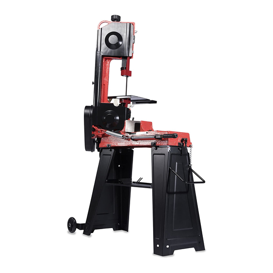
FEATURES
● Heavy duty steel base
with wheels
● Strong cast iron
head frame
● Cast iron vise opens to
6 in. (150 mm):
● Three speeds help to cut
ferrous and non-ferrous
metals
● Miter gauge allows 90º to 45º
cuts
● Adjustable blade guide
● Converts to vertical cutting
SPECIFICATIONS
● 120 V ~ 60 Hz 550 W
motor:
● Blade included:
64-1/2 in.
(1638 mm)
● Max. cutting capacity
(round):
4-1/8 in. (105 mm)
● Max. cutting capacity
(square): 4 x 6 in.
(102 x 150 mm)
● Blade speeds:
80 / 120 / 180 ft/min
(24 / 36.5 / 55 m/
min)
● CSA certification
● Net weight: 134 lb. (61
kg)
SETUP & OPERATION MANUAL
Model #
BS5205 man v.141110
4-1/2 inch
Metal Cutting
Band Saw
BS5205
Advertisement
Table of Contents

Related Manuals for General International BS5205


Summary of Contents for General International BS5205
-
Page 1: Metal Cutting
(square): 4 x 6 in. (102 x 150 mm) ● Blade speeds: 80 / 120 / 180 ft/min (24 / 36.5 / 55 m/ min) ● CSA certification ● Net weight: 134 lb. (61 Model # BS5205 BS5205 man v.141110... -
Page 2: Year Limited Warranty
2-year warranty period, subject to the “conditions and exceptions” as listed below. Repairs made without the written consent of General International will void the warranty. DISCLAIMER The information and specifications in this manual pertain to the unit as it was supplied from the factory at the time of printing. -
Page 3: Important Safety Instructions
Warranty does not include failures, breakage or defects deemed after inspection by General International to have been directly or indirectly ® caused by or resulting from; improper use, or lack of or improper maintenance, misuse or abuse, negligence, accidents, damage in handling or transport, or normal wear and tear of any generally considered consumable parts or components. -
Page 4: Warnings And Cautions
WARNINGS AND CAUTIONS Be sure to read, understand and follow all safety warnings and instructions in the supplied operator’s manual. WORK AREA 1. KEEP CHILDREN AND BYSTANDERS AWAY. All children should be kept away from the work area. Don’t let them handle machines, tools or extension cords. -
Page 5: Tool Safety
Knowledge is safety. 12. USE ONLY RECOMMENDED ACCESSORIES. Use of accessories NOT recommended by General International may result in a risk of injury. 141110... - Page 6 SERVICE 1. INSPECT AND MAINTAIN THE TOOL REGULARLY. Have it repaired only by an authorized repair technician. 2. MAINTAIN TOOLS WITH CARE. Keep tools sharp and clean for better and safer performance. Follow instructions for lubricating and safe performance. Follow instructions for lubricating and changing accessories.
- Page 7 (tables, saw horses, blocks, etc.) for any workpiece large enough to tip when not held down to the work table. 8. DO NOT LEAVE THE WORK AREA UNTIL ALL MOVING PARTS HAVE STOPPED. Shut off the power to master switches. Childproof the workshop! 9.
-
Page 8: Electrical Warnings And Cautions
27. KEEP THESE INSTRUCTIONS. Refer to them frequently and use them to instruct other users. If you loan someone this unit, also loan them the instructions. HEALTH NOTICE: Some dust created by power sanding, sawing, grinding, drilling, and other construction activities contain chemicals known to cause cancer, birth defects or other reproductive harm. -
Page 9: Grounding Instructions
GROUNDING INSTRUCTIONS In the event of an electrical malfunction or short circuit, grounding reduces the risk of electric shock. The motor of this machine is wired for 120 V single phase operation and is equipped with a 3-conductor cord and a 3-prong grounding plug to fit a grounded type receptacle (B, fig 1). -
Page 10: Functional Description
FUNCTIONAL DESCRIPTION GETTING TO KNOW YOUR BAND SAW WARNING! To avoid injury from accidental start, turn the switch off and remove the plug from the power source outlet before making any adjustments Leg assembly Tool tray Wheels Wheel frame Transport handle Pulley cover Work stop rod Lock chain... -
Page 11: Assembly Procedure
Band saw head assembly Leg assembly Tool tray Wheels Wheel frame Transport handle Worm gear pulley Motor shaft pulley V-belt Pulley cover Work stop rod Vertical cutting plate Vertical cutting support Accessory pack ASSEMBLY PROCEDURE WARNING! For your own safety, never connect the plug to the power source outlet or insert the switch insert key until all the assembly steps are complete and you have read and understood the entire owner's manual. - Page 12 3. Place the 3 bottom tabs of the connecting plates inside the leg assemblies (b, fig 6). 4. Locate 6 M8 washers (d, fig 7), and 6 M8 x 16 hexagon head bolts (c, fig 7). 5. Place a washer onto each hexagon head bolt. 6.
- Page 13 5. Locate the motor adjusting knob (k, fig 11). 6. Loosen, but do not fully unscrew, the motor adjusting knob by rotating it counter-clockwise. 7. Slide the kidney shaped hole of the lower pulley cover (l, fig 12) over the shaft (y, fig 12) of the motor (Y, fig 12).
-
Page 14: Transport Handle
13. Locate the V-Belt. 14. Lift the hinged motor and place the V-belt around the top grooves of both the motor pulley and the worm gear pulley. 15. Lower the hinged motor. 16. The band saw is now set at a speed of 80 f.p.m. (24 m/min). 17. -
Page 15: Work Stop
WORK STOP A work stop can be used to cut multiple work pieces to equal length without having to re-measure each piece individually. 1. Locate the work stop. This includes the work stop rod (r), the work stop (s) and the M8 x 10 hexagon socket set screw (see fig 22). 2. - Page 16 Such preventative safety measures reduce the risk of starting the tool accidentally. The General International 4-1/2 Inch Metal Cutting Band Saw can cut at any angle up to 45 degrees. 1. Locate the miter scale on the backside of the band saw (m, fig 26).
-
Page 17: Horizontal Cutting
FEED RATE─ ADJUSTING ROD The adjusting rod is used to control the pressure and speed of the band saw head as it lowers and cuts through the work piece. 1. Locate the adjusting rod (U, fig 2 & 28). The adjusting rod tightens or loosens a counter-balancing spring governing the weight that the head exerts on the blade.. - Page 18 4. Locate the blade back safety cover (bc, fig 33). 5. Locate the plum screw (p, fig 33) on the blade back safety cover. 6. Fully remove plum screw by rotating it counter-clockwise. 7. Open the blade back safety cover. 8.
-
Page 19: Maintenance
WARNING! When cutting metal, the area of the cut may be sharp and can cause damage to property and self. Be extremely careful when handling. CUTTING IN VERTICAL ORIENTATION 1. Identify and mark the cutting path on the work piece. 2. - Page 20 14. Rotate the blade tension adjustment knob counter-clockwise to allow the blade to slip off the rear blade wheel (r, fig 42) and the front blade wheel (f, fig 42). 15. Remove the old blade. 16. Place a new new 64-1/2 inch (1638 mm) blade between the bearings of the lower blade guard (b, fig 43).
-
Page 21: Blade Tracking
● Do not use a damaged tool. ● Never disassemble the tool or try to do any rewiring on the tool’s electrical system. Contact General International for all repairs. ● Clean dust and debris from vents. ● Keep the tool handles clean, dry and free of oil or grease. -
Page 22: Parts List
PARTS LIST DESCRIPTION QTY. DESCRIPTION QTY. DESCRIPTION QTY. Stop screw Supply cord Floor stand handle Spring Vertical cutting support plate Cotter pin 3 x 18 Screw M8 x 25 Vertical cutting plate Hexagon Head screw M8 x 20 Spring adjusting screw Hexagon nut M6 Washer 8 Rear nut plate... -
Page 23: Schematic Drawing
SCHEMATIC DRAWING 1 28 1 15 1 14 1 09 1 09 1 13 1 06 56 3 1 12 1 17 1 18 1 19 1 16 1 23 1 24 122 1 21 63 63 71 75 1 25 1 34 135 23 1 00... -
Page 24: Troubleshooting
TROUBLESHOOTING SYMPTOM POSSIBLE CAUSE CORRECTIVE ACTION Excessive blade breakage Work piece is loose in vise Clamp work securely Incorrect speed or feed Adjust blade speed or feed rate Blade tooth spacing too great Use a slower blade speed and higher TPI blade Incorrect blade tension Adjust tension to just where blade does... -
Page 25: Caractéristiques
● Capacité de coupe maximum (droit) : 4 x 6 po (102 x 150 mm) ● Vitesse de la lame : 80/120/180 pi/min (24/36.5/55 m/min) ● Certification CSA ● Poids net : 134 lb (61 kg) Modèle # BS5205 DEPUIS BS5205 man v.141110... - Page 26 NOUS VOUS REMERCIONS d’avoir choisi une machine de General International. Cette outil a été soigneusement testée et inspectée avant de vous être expédiée, et moyennant une utilisation et un entretien adéquats, elle vous procurera un service fiable pendant de nombreuses années. Afin d’obtenir un rendement optimal et une utilisation sans problème, et d’optimiser...
- Page 27 de réclamation de garantie peut vous être fourni sur demande par General International ou par un distributeur agréé) spécifiant clairement le ® modèle et le numéro de série de l’unité (si applicable), et faisant état de la plainte ou du défaut présumé, doivent être jointes au produit retourné. CONDITIONS ET EXCEPTIONS Cette couverture ne s’applique qu’au premier acheteur.
-
Page 28: Avertissements Et Précautions
AVERTISSEMENTS ET PRÉCAUTIONS Assurez-vous de lire, comprendre et suivre tous les avertissements et consignes de sécurité dans le manuel de l'opérateur. ZONE DE TRAVAIL 1. TENEZ LES ENFANTS ELOIGNÉS. Assurez-vous que les visiteurs sont maintenus à une distance sécuritaire de la zone de travail. 2. - Page 29 9. TOUJOURS DÉBRANCHER L’OUTIL AVANT DE FAIRE L’ENTRETIEN et changer les accessoires tels que la lame. 10. VÉRIFIER QUE LES CLÉS ET MOLETTES DE RÉGLAGE SONT RETIRÉES avant la mise sous tension, laisser en place ces pièces peuvent s'envoler au démarrage et entraîner des blessures. 11.
- Page 30 boulons ou vis qui se sont relâches. Toute pièce endommagée doit être correctement réparée ou remplacée par un centre de service autorisé, sauf indication contraire ailleurs dans le manuel d'instruction. Faite remplacer un interrupteur défectueux par un centre de service agréé. Ne pas utiliser l'outil si le commutateur ne fonctionne pas correctement.
- Page 31 1. LISEZ LES AVERTISSEMENTS SUR L’OUTIL. 2. ÉVITEZ TOUT DÉMARRAGE INVOLONTAIRE. Assurez-vous que le commutateur est en position ARRET/OFF avant de brancher. 3. VÉRIFIEZ ET ASSUREZ VOUS DE RETITREZ TOUTES CLÉS ET CLÉS D’AJUSTEMENTS avant de mettre l'outil en marche. Si vous laissez ces pièces elles peuvent s'envoler et entraîner des blessures.
- Page 32 18. LES PIÈCES RONDES DOIVENT ETRE PROPREMENT SUPPORTÉES. Utiliser des blocs en V pour l'empêcher de rouler. 19. UTILISEZ LA BONNE VITESSE DE COUPE pour un bon fonctionnement sur un matériel spécifique - vérifiez l'étiquette pour information. 20. GARDER LE COUVERCLE DES POULIES FERMÉ quand vous ne faites pas d’ajustements à...
-
Page 33: Instructions De Mise À La Terre
2. ASSUREZ-VOUS QUE VOS DOIGTS ne touche pas les bornes du cordon d'alimentation au moment de brancher ou débrancher l'outil. 3. DES OUTILS MISE À LA TERRE DOIVENT ÊTRE BRANCHÉS dans une prise tripolaire dument installée. La mise à terre crée un chemin de basse résistance qui conduit l’électricité... -
Page 34: Description Fonctionnelle
Longueur totale de la rallonge Calibre en Pieds Mètres Pieds Mètres Pieds Mètres Pieds Mètres ampères 3-10 A ca. 18 ca. 16 ca. 14 ca. 14 10,1 - 12 A ca. 16 ca. 16 ca. 14 ca. 14 12,1 - 16 A ca. -
Page 35: Procédure D'assemblage
DÉBALLAGE ATTENTION! Ne tentez pas d’assembler l'outil, de brancher le cordon d'alimentation ou appuyer sur l'interrupteur si des pièces sont endommagées ou manquantes. Le non respect de cet avertissement peut entraîner des blessures graves. CONTENU Séparez toutes les pièces des matériaux d'emballage et comparez soigneusement avec fig 2 de la liste ci-dessous. - Page 36 8. Placez une rondelle sur chaque vis M6 x 10. 9. Insérez complètement la vis à tête hexagonale avec une première rondelle, à travers chacun des trous de la tablette (fig 4), puis sur les trous de l'assemblage de jambe. 10.
- Page 37 3. Repérez les six boulons M8 x 25 à tête hexagonale et les six rondelles 4. Placez une rondelle sur chaque boulon à tête hexagonale. 5. Visser le boulon à tête hexagonale un dans chaque trou du support de plaque (t, figure 8), puis dans la base de la tête de la scie à ruban (e, fig 8).
-
Page 38: Poignée De Transport
6. Remettre en place la vis M4 x 8 dans le trou n° 2 et dans la rondelle de caoutchouc. Cette vis a été retirée à l'étape 4 de la présente section. 7. Localisez la poulie du moteur et poulie à engrenage sans fin. 8. - Page 39 ROUES 1. Localisez le cadre de roue (E, fig 2). 2. Placez le cadre de l roue contre le bas de la base. REMARQUE : Installez le cadre de roue sur le même coté que le moteur. 3. Aligner les trous du cadre de roue avec les trous du support. Lors de l'alignement des trous, assurez-vous que le cadre de roue est au niveau de la sol.
- Page 40 Ces mesures de sécurité préventives réduisent le risque de démarrage de l'outil accidentellement. La scie à ruban General International de 4-1/2 pouces peut couper à n'importe quel angle jusqu'à 45 degrés. 1. Localisez l'échelle d'onglet à l'arrière de la scie à ruban (m, fig 26).
- Page 41 COUPE VITESSE DE LA LAME / POSITION DE COURROIE Lorsque vous utilisez votre scie à ruban, toujours changer la vitesse de la lame en fonction du matériel à coupé. 1. Établir la vitesse pour le matériau à découper. MATÉRIAUX À COUPÉ VITESSE Acier inoxydable 80 pi/min...
- Page 42 Cette scie utilise une lame unique, fonctionnant sur 2 roues. 1. Décrocher la chaîne de verrouillage (O, fig 2) de la languette de verrouillage, libérant l’interrupteur pour permettre son utilisation. 2. Une fois que vous avez configuré votre scie à ruban pour la vitesse appropriée pour le matériel et fixé...
- Page 43 13. Localisez la plaque de coupe verticale (HH, fig 35). 14. Localisez support de plaque de coupe verticale (ps, fig 36), une vis M6 x 12 à tête cruciforme, un écrou hexagonal M6 et une rondelle M6. 15. Insérez la vis dans le trou n° 1, fig 35 de la plaque coupe verticale. 16.
-
Page 44: Entretien
ENTRETIEN ATTENTION! Toujours débrancher l'outil de la source d'alimentation avant d'effectuer des réglages, l'entretien, ou de changer les accessoires ou l’entreposage. Ces mesures de sécurité préventives réduisent le risque de démarrage de l'outil accidentellement. CHANGER LA LAME 1. Soulevez la tête en position verticale (fig 40).. 2. -
Page 45: Ajustement De Lame
23. Fermez le couvercle de la lame. 24. Remplacer la vis à grosse tête. 25. Remplacer la languette d interrupteur avec sa vis, retirée à l'étape 6. REMARQUE : l'onglet d’interrupteur devrait être en mesure d’éteindre la scie lorsqu'il est placé dans la position horizontale. Cette scie à... - Page 46 ● Utilisez un savon doux et un chiffon humide pour nettoyer votre outil car certain des agents de nettoyage et les solvants sont nocifs pour les matières plastiques et autres isolants. Certains de ces solvants sont nocifs comprennent: l'essence, l'essence de térébenthine, des diluants pour vernis, diluant à...
- Page 47 TROUBLESHOOTING PROBLÈME CAUSE POSSIBLE SOLUTIONS Rupture excessive de la lame Pièce de travail est desserrée dans un Serrer la pièce dan l’étau étau Vitesse incorrect ou alimentation trop Ajuster la vitesse de la lame et son rapide alimentation Espacement des dents trop grand Ajuster à...
-
Page 48: Liste Des Pièces
LISTE DES PIÈCES DESCRIPTION QTÉ. DESCRIPTION QTÉ. DESCRIPTION QTÉ. Vis d’arrêt Support vertical de coupe Poignée du support Ressort Plaque Goupille 3 x 18 Vis M8 x 25 Plaque de support vertical Vis à tête hexagonale M8 x 20 Vis de réglage à ressort Écrou hexagonal M6 Rondelle 8 Écrou plaque arrière... - Page 49 SCHEMATIC DRAWING 1 28 1 15 1 14 1 09 1 09 1 13 1 06 56 3 1 12 1 17 1 18 1 19 1 16 1 23 1 24 122 1 21 63 63 71 75 1 25 1 34 135 23 1 00...
Need help?
Do you have a question about the BS5205 and is the answer not in the manual?
Questions and answers