Table of Contents
Advertisement
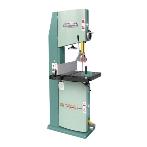
SETUP & OPERATION MANUAL
FEATURES
Heavy-duty one-piece frame, designed for
added stability. Requires no further assembly.
Dynamically balanced cast-iron wheels
with replaceable rubber tires,mounted on
heavy-duty bearings.
Solid cast-iron table with heavy-duty onepiece
trunnion and 0-45° right tilting action for bevel
cuts.
Upper and lower dual bakelite block and 5
bearing deluxe blade guide system, with 10
points of contact. (Model 90-290 only)
2 cutting speeds for excellent results in either
hard or soft woods. (Model 90-290 only)
Convenient blade tension adjustment hand-
wheel with tension scale.
Safety foot brake simultaneously slows down
the blade and disconnects electrical circuit for
quick blade stoppage and emergency shut-
off.
Powerful, totally enclosed fan cooled (TEFC)
industrial quality motor.
Magnetic safety switch with lock-out switch key
to prevent unauthorized use.
Cast-iron miter gauge and dual miter slots in
table for stable cross cuts on either side of the
blade.
Deluxe Excalibur bandsaw rip fence system
with curved guide block and a 6" wooden
resaw auxiliary fence.
Onboard storage mounts for miter gauge rip
fence.
Short cut-off feed device keeps fingers safely
away from the blade.
* Model 90-290 only. Model 90-380 has 7 bearings.
SPECIFICATIONS
WHEEL SIZE
18" (458 mm) – 90-290
22" (560 mm) – 90-380
WHEEL SPEED
(2) 600/840 rpm – 90-290
(1) 800 rpm – 90-380
MAX/MIN BLADE WIDTH
1 1⁄4" (32 mm)/1⁄4" (6 mm)
BLADE LENGTH
145 5/8" (3700 mm) – 90-290
171 1⁄4" (4350 mm) – 90-380
BLADE SPEED
2820 & 3936 lin. fpm (860/1200 lin. mpm) – 90-290
4590 lin. fpm (1400 lin. mpm) – 90-380
TABLE SIZE/TABLE HEIGHT
24" x 20" (610 x 510 mm)/37 3⁄8" (950 mm) – 90-290
30" X 22 3/4" (765 X 580 mm)/35 1⁄4" (895 mm) – 90-380
TABLE TILT
0°- 45° (Right)
MAX. WIDTH OF CUT/MAX. DEPTH OF CUT
17 5/8" (450 mm)/12" (305 mm) – 90-290
21 5/8" (550 mm)/16" (407 mm) – 90-380
MAXIMUM CUTTING (RIP FENCE)
16" (405 mm) – 90-290
19 5/8" (500 mm) – 90-380
DUST COLLECTION PORTS
2 x 4" (102 mm)
MOTOR
90-290 M1: 3 HP, 220 V 1PH 16 A
90-290 M2: 3 HP, 220 V, 3PH, 8.4 A
90-290 M3: 3 HP, 600 V, 3PH, 3.5 A
90-380 M1: 5 HP, 220 V, 1PH, 26 A
90-380 M2: 7.5 HP, 220/440 V, 3PH, 22/11 A
90-380 M3: 7.5 HP, 600 V, 3PH, 8 A
WEIGHT
605 lbs (275 kg) – 90-290
825 lbs (375 kg) – 90-380
18"/22" WOOD CUTTING BANDSAW
MODEL
# 90-290
#90-380
VERSION 3_REVISION 3 - JUNE 2015
© Copyright General® International
(90-380: 92255913)
Advertisement
Table of Contents

Related Manuals for General International 90-290


Summary of Contents for General International 90-290
-
Page 1: Specifications
2820 & 3936 lin. fpm (860/1200 lin. mpm) – 90-290 4590 lin. fpm (1400 lin. mpm) – 90-380 TABLE SIZE/TABLE HEIGHT 24” x 20” (610 x 510 mm)/37 3⁄8” (950 mm) – 90-290 30” X 22 3/4” (765 X 580 mm)/35 1⁄4” (895 mm) – 90-380 TABLE TILT MODEL 0°- 45°... - Page 2 Telephone (514) 326-1161 • Fax (514) 326-5555 • www.general.ca THANK YOU for choosing this General International model 90-290/90-380 ® 18”/22” Wood Cutting Bandsaw. This bandsaw has been carefully tested and inspected before shipment and if properly used and maintained, will provide you with years of reliable service.
- Page 3 GENERAL ® INTERNATIONAL WARRANTY All component parts of General ® International and Excalibur by General International ® products are carefully inspected during all stages of production and each unit is thoroughly inspected upon completion of assembly. Limited Lifetime Warranty Because of our commitment to quality and customer satisfaction, General ® International agrees to repair or replace any part or component which upon examination, proves to be defective in either workmanship or material to the original purchaser for the life of the tool.
-
Page 4: Table Of Contents
Adjusting the blade guard for depth of cut ..20 Unpacking ..........Changing spped settings ..20 (model 90-290 only) List of contents ............8 Positioning the upper/lower blade guides ..19 Additional requirements for set up ......8 Align the laser line marker to the blade ....21 Clean up............. -
Page 5: Rules For Safe Operation
Rules for Safe Operation To help ensure safe operation, please take a moment to learn the machine’s applications and limita- tions, as well as potential hazards. General® International disclaims any real or implied warranty and hold itself harmless for any injury that may result from the improper use of it’s equipment. 1. -
Page 6: Electrical Requirements
ELECTRICAL REQUIREMENTS BEFORE CONNECTING THE MACHINE TO THE POWER SOURCE, VERIFY THAT THE VOLTAGE OF YOUR POWER SUPPLY CORRE- SPONDS WITH THE VOLTAGE SPECIFIED ON THE MOTOR I.D. NAMEPLATE. A POWER SOURCE WITH GREATER VOLTAGE THAN NEED- ED CAN RESULT IN SERIOUS INJURY TO THE USER AS WELL AS DAMAGE TO THE MACHINE. IF IN DOUBT, CONTACT A QUALIFIED ELECTRICIAN BEFORE CONNECTING TO THE POWER SOURCE. -
Page 7: Identification Of Main Parts And Components
IDENTIFICATION OF MAIN PARTS AND COMPONENTS FRONT VIEW A- UPPER WHEEL COVER DOOR LOCK KNOB B- BLADE GUARD HEIGHT ADJUSTMENT HANDWHEEL C- PUSH HANDLE D- BLADE TENSION ADJUSTMENT HANDWHEEL MAGNETIC SAFETY SWITCH UPPER BLADE GUIDE SYSTEM G- MITER GAUGE H- RIP FENCE TABLE LOWER WHEEL COVER DOOR LOCK KNOB K- FOOT BRAKE... -
Page 8: Unpacking
M- 4 MM ALLEN KEY* ............1 N- 6 MM ALLEN KEY* ............1 O- 8 MM ALLEN KEY* ( Model 90-290 only) ......1 P- PUSH HANDLE ............... 1 Q- 10 MM OPEN END WRENCH* ........1 R- FRONT FENCE LOCK KNOB * ........2 S- SQUARE NUT* ............... -
Page 9: Basic Functions Of The Unit
The Maximum inboard width of cut (space between the blade and the body of the saw A) is 17 5/8” for the 90-290 and 21 5/8” for the 90-380. For cutting thicker stock or for resawing, the maximum depth of cut B (or max. -
Page 10: Placement Within The Shop / Establishing A
C to the left side of the saw as shown, using the bolts and washers already mounted to the saw. INSTALL THE FOOT BRAKE (MODEL 90-290 ONLY) 1. Open the lower wheel cover door. 2. Attach the foot brake to the foot brake mounting bar as shown using the two 3/8”... -
Page 11: Install The Blade Tension Adjustment Handwheel Handle
INSTALL THE HANDLE ON THE BLADE GUARD HEIGHT ADJUST- INSTALL THE PUSH HANDLE MENT HANDWHEEL 1. Thread the handle A on the blade guard adjust- 3. Attach the push handle to the push handle bracket ment handwheel as shown in B. as shown using the two wing nuts A already 2. -
Page 12: Safety Lock-Out Switch
SAFETY LOCK-OUT SWITCH To prevent unauthorized use, this bandsaw is also equipped with a safety lock-out switch with removable key, D, located at the front of the machine, on the control panel, A. CONTROL PANEL When this switch is locked, the machine cannot be started by pressing on the green “on”... -
Page 13: Adjusting The 90º Table Stop And Re-Aligning The Angle Pointer
Push the table locking lever B to the left to unlock the table. Loosen the table lock knob C and tilt the table until it is at the desired angle. (Refer to the angle indica- tor A.) Re-tighten lock knob C and push locking lever B to the right to lock the table in position. -
Page 14: Blade Selection
Ask your local tool dealer for suggestions for bandsaw blades in 1/4” to 1 1/4” widths, based on what is available in your area. Ideal blade length for model 90-290 is 145 5/8” and 171 1/4” for model 90-380. Note: Generally speaking, because the upper wheel height is somewhat adjustable (to allow for blade tensioning), a blade length variation of plus or minus 1/2”... - Page 15 To remove a blade: DO NOT ATTEMPT TO COIL UP THE BLADE AS IT WAS WHEN YOU FIRST PURCHASED IT AS IT HAS A TENDANCY TO POP OPEN UNEXPECTEDLY AND COULD CAUSE INJURY. 1. Turn off the bandsaw and unplug the power cord. 2.
-
Page 16: Adjusting Blade Tension
ADJUSTING BLADE TENSION Determining ideal blade tension is somewhat subjective. It is learned through practice and experience and is some- what dependant on personal preference and individual work habits. A properly tensioned blade is critical to obtaining maximum performance from any bandsaw. A properly tensioned blade will last longer and be much less likely to break prematurely. -
Page 17: Adjusting Blade Tracking
ADJUSTING BLADE TRACKING 3 mm - 1/8” Ideally, the blade should stay relatively centered A on both the upper and lower wheels. Due to natural variations in castings, blade thickness or den- sity and tire wear, absolute perfect centering alignment is rarely attainable. -
Page 18: Adjusting The Upper/Lower Blade Guides And Thrust Bearig
Note The upper and lower wheels are factory set to allow for easy and optimal blade tracking adjustment s using the primary blade tracking adjustment handwheel, which adjusts the angle of tilt of the upper wheel. In extremely rare cases, if acceptable blade tracking cannot be attained through the primary adjustment it may eventually become necessary to make minor adjustments to the angle of tilt of the lower wheel. -
Page 19: Positioning The Upper/Lower Blade Guides
POSITIONING THE UPPER/LOWER BLADE GUIDES The space between each bearing and the blade must not exceed 0.02” (the thickness of a sheet of paper ). If less space is left, the blade will get stuck or jammed between both bearings. Too much friction will cause blade to over- heat and break. -
Page 20: Adjusting The Blade Guard For Depth Of Cut
CHANGING SPEED SETTINGS (model 90-290 only) The model 90-290 has 2 different speed settings; low and high. - Low speed is to be used for cutting soft woods over 4” in height or hard woods over 2” in height. -
Page 21: Align The Laser Line Marker To The Blade
ALIGN THE LASER LINE MARKER TO THE BLADE The laser line marker shines a straight line beam of light representing the line of cut onto the workpiece. To align the marker to the blade: 1. Place your workpiece on the table and set the height of the blade guard. -
Page 22: Operations Step-By-Step
OPERATIONS STEP-BY-STEP TO REDUCE THE RISK OF DAMAGE TO THE BANDSAW OR THE WORKPIECE, AS WELL AS POTENTIAL FOR PERSONAL INJU- RY, AFTER INITIAL SET-UP AS WELL AS BEFORE EACH USE, MAKE SURE THAT EVERYTHING IS SECURELY INSTALLED AND THAT ALL FASTENERS AND MOVING PARTS ON THIS BANDSAW ARE LOCKED IN PLACE BEFORE STARTING THE MACHINE. Trace the cutting line on your workpiece with a pencil (for cutting curves) or adjust the laser beam to mark the cutting line (for cutting straight lines). -
Page 23: Using The Push Handle
USING THE PUSH HANDLE The push handle helps to reduce the risk of user inju- ry through contact with the blade. It acts as a stock feeder allowing you to push the last few inches of the board through the blade as shown, while keeping hands at a safe distance away from the blade. -
Page 24: Lubrication
TO AVOID EYE INJURY FROM BLOWING DEBRIS, WEAR SAFETY GOGGLES WHEN BLOWING OUT SAWDUST. 3. Keep the machine clean and free of sawdust. Frequently blow out or vacuum up the sawdust and occasion- ally wipe down the machine with a damp rag. Note: The wheels must always be kept clean. -
Page 25: Replacing The Upper And Lower Blade Guides And Thrust Bearings
Using the supplied 3 mm Allen key, loosen and remove bolt E. Remove the thrust bearing and mounting shaft H. Model 90-290 Model 90-380 Using a 2.5 mm Allen key, loosen and remove the set 10. To remove the thrust bearing from it’s shaft, J, use C- screw I on both left and right red mounts. -
Page 26: Replacing The Wheel Tire
REPLACING LOWER WHEEL MOTOR BELT(S*) *The lower wheel on model 90-290 is driven by one belt while the lower wheel on model 90-380 is driven by two belts The lower wheel is driven by (a) belt(s*) mounted on a pulley powered by the motor. The belt(s*) tension should be verified upon reception of the machine, then every 6 months. -
Page 27: Recommended Optional Accessories
RECOMMENDED OPTIONAL ACCESSORIES Here are some optional accessories available from your local General International dealer for increased con- venience, accuracy and safety when using your bandsaw. For more information about our products, please visit our website at www.general.ca DUST COLLECTORS... -
Page 28: Parts List & Diagrams
MAIN ASSEMBLY – 90-290... - Page 29 BLADE GUIDE AND BLADE GUARD ASSEMBLY – 90-290 114-1 114-1 114-2 114-2...
- Page 30 TABLE ASSEMBLY – 90-290 229-1 229-2 229-6 229-3 229-4 229-5 224A...
- Page 31 PARTS LIST – 90-290 M1 REF. N0. PART. N0. DESCRIPTION SPECIFICATION 90290-01 BODY 90290-02 BLADE TENSION LABEL 90290-03 HANDWHEEL 90290-04 HEX NUT 3/8” 90290-05 HOUSING 90290-06 NYLON NUT 12MM 90290-07 HEX BOLT 5/16”X3/4” 90290-08 HEX NUT 5/16” 90290-09 HEX BOLT...
- Page 32 PARTS LIST – 90-290 M1 REF. N0. PART. N0. DESCRIPTION SPECIFICATION 90290-55 HEX NUT 1/2” 90290-56 HEX BOLT 3/8”X2” 90290-57 FLAT WASHER 3/8” 90290-58 BUSHING 90290-59 LOCK NUT 3/8” 90290-60 FLAT WASHER 3/8” 90290-61 HEX BOLT 3/8”X1 1/2” 90290-62 RATCHET HANDLE...
- Page 33 PARTS LIST – 90-290 M1 REF. N0 PART. N0. DESCRIPTION SPECIFICATION 90290-118 FLAT WASHER 3/8” 90290-119 CAP SCREW 8X55 MM 90290-120 BLADE GUIDE BRACKET 90290-121 BLADE GUIDE BRACKET SHAFT 90290-122 HEX NUT 90290-123 SET SCREW 6X50 MM 90290-124 ADJUSTMENT NUT...
- Page 34 MITER GAUGE ASSEMBLY – 90-290 & 90-380 PARTS LIST – 90290-229 REF. N0. PART N0. DESCRIPTION SPECIFICATION 229-M1 90290-229M1 WASHER 229-M2 90290-229M2 HANDLE 229-M3 90290-229M3 3/16’-24UNC 229-M4 90290-229M4 SET SCREW 3/16’-24UNC-3/4”L 229-M5 90290-229M5 MITER GAUGE HEAD 229-M6 90290-229M6 FLAT HEAD SCREW 3/16’-24UNC-3/8”L...
- Page 35 PUSH HANDLE ASSEMBLY – 90-290 & 90-380 PARTS LIST – 90290-238 REF. N0. PART N0. DESCRIPTION SPECIFICATION 90290-A1 MAIN BASE 90290-A2 FLAT WASHER 1/4” 90290-A3 LOCK WASHER 1/4” 90290-A4 HEX BOLT 1/4”X5/8” 90290-A5 HEX NUT 5/16” 90290-A6 T TYPE BASE...
- Page 36 MAIN ASSEMBLY – 90-380...
- Page 37 BLADE GUIDE AND BLADE GUARD ASSEMBLY – 90-380 114-1 114-1 114-2 114-2...
- Page 38 TABLE ASSEMBLY – 90-380 229-1 229-2 229-3 229-4 229-5 224A...
- Page 39 PARTS LIST – 90-380 M1 REF. N0. PART. N0. DESCRIPTION SPECIFICATION 90380-01 BODY 90380-02 HEX BOLT 5/16”X1 1/4” 90380-03 LOCK WASHER 5/16” 90380-04 FLAT WASHER 5/16” 90380-05A HOUSING 90380-06 PHILLIPS HEAD SCREW 3/16”X1/2” 90380-07 BLADE TENSION POINTER 90380-08 BLADE TENSION LABEL 90380-09 POINTER COVER 90380-10...
- Page 40 PARTS LIST – 90-380 M1 REF. N0. PART. N0. DESCRIPTION SPECIFICATION 90380-59 LOCK NUT 3/8” 90380-60 FLAT WASHER 3/8” 90380-61 HEX BOLT 3/8”X1 1/2” 90380-62 HEX BOLT 1/2”X1 1/2” 90380-63 LOCK WASHER 1/2” 90380-64 FLAT WASHER 1/2” 90380-65 HEX BOLT 3/8”X5”...
- Page 41 PARTS LIST - 90-380 M1 REF. N0 PART. N0. DESCRIPTION SPECIFICATION 90290-120 BLADE GUIDE BRACKET 90290-121 BLADE GUIDE BRACKET SHAFT 90380-122 HEX NUT 90380-123 SET SCREW 6X50MM 90290-124 ADJUSTMENT NUT 90380-125 CAP SCREW 5/16”X1 1/4” 90290-126 SLIDE BLOCK 90380-127 HEX BLOCK 90380-128 BLADE GUARD 90290-129...
- Page 42 MODEL 90-290/90-380 8360 Champ-d’Eau, Montreal (Quebec) Canada H1P 1Y3 Tel.: (514) 326-1161 Fax: (514) 326-5565 - Fax: (514) 326-5555 - Parts & Service / Order Desk orderdesk@general.ca www.general.ca IMPORTANT When ordering replacement parts, always give the model number, serial number of the machine and...
Need help?
Do you have a question about the 90-290 and is the answer not in the manual?
Questions and answers