Table of Contents
Advertisement
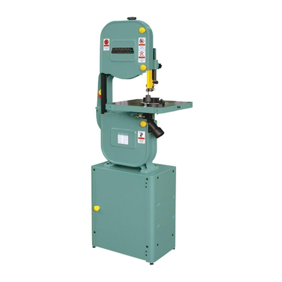
SETUP & OPERATION MANUAL
FEATURES
Cast-iron frame & precision-balanced alu-
minum wheels with replaceable rubber
tires.
Sturdy, easy to assemble, closed base steel
stand.
Precision aluminum miter gauge with han-
dle.
2 cutting speeds for excellent results in
either hard or soft woods.
Hinged door and easily accessible blade
tension knob, for fast blade changes or
adjustments.
Ball-bearing and carbon block blade
guide assembly.
Built-in blade cleaning brush keeps tires
free of dust and chips.
Safety lock-out switch with removable key
to prevent unauthorized use.
SPECIFICATIONS
WHEEL SIZE
13 7⁄8 " (353 mm)
WHEEL SPEEDS (2)
470/820 RPM
MAXIMUM BLADE WIDTH
3⁄4" (19 mm)
MINIMUM BLADE WIDTH
1⁄4" (6 mm)
BLADE LENGTH
93 1⁄2" (2375 mm)
BLADE SPEEDS (2)
1630 & 2730 LIN. FPM (495/832 LIN. MPM)
TABLE SIZE
16" x 16" (406 x 406 mm)
TABLE TILT
0°- 45° (RIGHT) / 0°-10° (LEFT)
TABLE HEIGHT
42" (1067 mm)
MAXIMUM WIDTH OF CUT
13 1⁄2" (343 mm)
MAXIMUM DEPTH OF CUT
6" (150 mm)
DUST COLLECTION PORT
2 1⁄2" (63 mm)
BASE DIMENSIONS (L x W)
19 5⁄8" x 13" (498 x 330 mm)
MOTOR
1 HP , 110 V, 1 PH, 10 A
WEIGHT
191 LBS (87 kg)
14" WOOD CUTTING BANDSAW
MODEL
# 90-140 M1
REVISION 1 - March 10/10
© Copyright General® International 03/2010
Advertisement
Table of Contents

Related Manuals for General International 90-140 M1


Summary of Contents for General International 90-140 M1
-
Page 1: Specifications
MODEL 13 1⁄2” (343 mm) MAXIMUM DEPTH OF CUT 6” (150 mm) DUST COLLECTION PORT # 90-140 M1 2 1⁄2” (63 mm) BASE DIMENSIONS (L x W) 19 5⁄8” x 13” (498 x 330 mm) MOTOR 1 HP , 110 V, 1 PH, 10 A... - Page 2 THANK YOU for choosing this General ® International model 90-140 M1 14” Wood Cutting Bandsaw. This bandsaw has been carefully tested and inspected before ship- ment and if properly used and maintained, will provide you with years of reliable service. For...
- Page 3 ® ® GENERAL & GENERAL INTERNATIONAL WARRANTY All component parts of General®, General® International and Excalibur by General International ® products are carefully inspected during all stages of production and each unit is thoroughly inspected upon completion of assembly. Limited Lifetime Warranty Because of our commitment to quality and customer satisfaction, General®...
-
Page 4: Table Of Contents
TABLE OF CONTENTS Blade clearance ......15 Rules for safe operation ....To remove a blade . -
Page 5: Rules For Safe Operation
Rules for Safe Operation To help ensure safe operation, please take a moment to learn the machine’s applications and limita- tions, as well as potential hazards. General® International disclaims any real or implied warranty and hold itself harmless for any injury that may result from the improper use of it’s equipment. 1. -
Page 6: Electrical Requirements
ELECTRICAL REQUIREMENTS BEFORE CONNECTING THE MACHINE TO THE POWER SOURCE, VERIFY THAT THE VOLTAGE OF YOUR POWER SUPPLY CORRESPONDS WITH THE VOLTAGE SPECIFIED ON THE MOTOR I.D. NAMEPLATE. A POWER SOURCE WITH GREATER VOLTAGE THAN NEEDED CAN RESULT IN SERIOUS INJURY TO THE USER AS WELL AS DAMAGE TO THE MACHINE. IF IN DOUBT, CONTACT A QUALIFIED ELECTRICIAN BEFORE CONNECTING TO THE POWER SOURCE. -
Page 7: Identification Of Main Parts And
IDENTIFICATION OF MAIN PARTS AND COMPONENTS FRONT VIEW BLADE TENSION ADJUSTMENT KNOB BLADE GUARD LOCK KNOB UPPER BLADE GUIDE ASSEMBLY BLADE GUARD MITER GAUGE TABLE ALIGNMENT PIN DUST PORT BASE CABINET TABLE TILT LOCK KNOB LOWER WHEEL COVER DOOR ON/OFF SWITCH W/SAFETY KEY UPPER WHEEL COVER DOOR REAR VIEW BLADE TRACKING ADJUSTMENT KNOB... -
Page 8: Unpacking
UNPACKING Carefully unpack and remove the unit and its components from its shipping container and check for missing or damaged items as per the list of contents below. NOTE: Please report any damaged or missing items to your GENERAL® INTERNATIONAL distributor immediately. LIST OF CONTENTS Once the parts have been removed from the packag- ing, you should have the following items:... -
Page 9: Basic Functions Of The Unit
“Recommended Optional Accessories for your Bandsaw”. PLACEMENT WITHIN THE SHOP / ESTABLISHING A SAFETY ZONE THIS MODEL 90-140 M1 BANDSAW IS HEAVY (191 LBS - 87 KG). DO NOT OVER-EXERT. THE HELP OF AN ASSISTANT WILL BE NEEDED FOR THE FOLLOWING STEP . -
Page 10: Assembly Instructions
ASSEMBLY INSTRUCTIONS SERIOUS PERSONAL INJURY COULD OCCUR IF YOU CONNECT THE MACHINE TO THE POWER SOURCE BEFORE YOU HAVE COMPLETED THE INSTALLATION AND ASSEMBLY STEPS. DO NOT CONNECT THE MACHINE TO THE POWER SOURCE UNTIL INSTRUCTED TO DO SO. ASSEMBLE THE BASE CABINET 1. -
Page 11: Install The Bandsaw Onto The Base Cabinet
INSTALL THE BANDSAW ONTO THE BASE CABINET The bandsaw mounts onto a base cabinet which provides storage space for the miter gauge and replacement- blades. Important! Make sure all stand fasteners are firmly tightened and that the stand cabinet is installed on a solid, flat and sta- ble floor that is able to support the weight of the bandsaw 191 LBS (87 kg) The bandsaw is heavy. -
Page 12: Attaching The Table
ATTACHING THE TABLE Remove the red insert A from the center of the Turn the table right side up. Verify that the long table and the table alignment pin B from the table bolts C in the center of each trunnion are pointing slot. -
Page 13: Miter Gauge
MITER GAUGE POWER CORD HOOKS The miter gauge rides in the table slot to the right of the When the bandsaw is not in use, we recommend that blade A and can be set to any angle up to 30° to the the power cord be wound up neatly around the two left or right B. -
Page 14: Recommended Adjustments
RECOMMENDED ADJUSTMENTS ADJUSTING THE 90º TABLE STOP AND RE-ALIGNING THE ANGLE POINTER To ensure that your 90º cuts are square and that angled cuts are accurate with the angle indicator scale, the table default position must be set to 90º to the blade and the angle indicator pointer must be set to read 0 when the table is in the default (90º) position. -
Page 15: Removing/Installing The Blade
REMOVING / INSTALLING THE BLADE Your bandsaw is designed to handle several blade widths ranging from 1/4” and 3/8” used for tight radius curves, up to 1/2” and 3/4” for larger radius curves or for cutting thicker stock. BLADE CLEARANCE Note: When performing blade installation, removal, tensioning or tracking, maximum clearance between the blade and both upper and lower blade guide assemblies is required to minimize friction, which would be damaging to the blade. -
Page 16: Blade Selection
Blade teeth are sharp. Use care when handling a saw blade. Open the top and bottom wheel cover doors and bring the left hand side of the loose blade toward you and out of the left hand blade guard slot F. Note: You may want to use a thick shop towel to handle the loose blade or wear a pair of heavy duty work gloves . -
Page 17: Adjusting Blade Tension
When working with narrower blades, sawing shorter stock and making tighter curved cuts are best per- formed using less tension This model 90-140 M1 bandsaw is equipped with a blade tension scale, which can be used as a reference for the ideal setting with various blade widths. -
Page 18: Adjusting Blade Tracking
ADJUSTING BLADE TRACKING 3 mm - 1/8" Blade tracking means centering the blade on the wheels A. Ideally, the blade should stay relatively centered on both the upper and lower wheels. Due to natural variations in castings, blade thickness or den- sity and tire wear, absolute perfect centering alignment is rarely attainable. -
Page 19: Adjusting The Blade Guard For Depth Of Cut
ADJUSTING THE BLADE GUARD FOR DEPTH OF CUT The blade guard can be moved up or down to accom- REAR VIEW modate the height of the work to be cut. To prevent the blade (which is flexible and which would not otherwise be supported) from slipping out of position during cut- ting, and to reduce risks of injuries, a minimum amount 1/8”... -
Page 20: Positioning The Lower Guide Blocks And Thrust Bearing
3. Pinch a feeler gauge C between one of the guide 5. Loosen the lower thumb screw F. blocks and the blade D, and then tighten the set 6. Turn the micro lower adjust nut G to move the guide screw E to set the gap between the guide block block assembly in or out until the guide blocks are and the blade. -
Page 21: Changing Speed Settings
CHANGING SPEED SETTINGS This model 90-140 14" wood cutting bandsaw has 2 different speed settings; low and high. Low speed is to be used for cutting soft woods over 4" in height or hard woods over 2" in height. High speed is best for cutting soft woods under 4" in height or hard woods under 2" in height. Note: If wood starts to burn at high speed, stop and change to the lower speed setting. -
Page 22: Connecting To A Dust Collector
CONNECTING TO A DUST COLLECTOR A dust port with a 2.5” opening is provided to accommodate connection to a dust collector (not included). Once the dust port has been installed (See Previous section “Attaching the dust port”), be sure to use appropriate sized hose and fittings (not included) and check that all connec- tions are sealed tightly to help minimize airborne dust. -
Page 23: Cutting Curves
CUTTING CURVES • When cutting curves, carefully turn the workpiece so the blade follows without twisting. If the curve is so sharp that you repeatedly back up and cut new kerf, use a narrower blade, or a blade with more set (teeth further apart). When a blade has more set, the workpiece turns easier but the cut is rougher. -
Page 24: Required Maintenance
To avoid eye injury from blowing debris, wear safety goggles when blowing out sawdust. 3. Keep the machine clean and free of sawdust. Frequently blow out or vacuum up the sawdust and wipe down the machine occasionally with a damp rag. Note: The wheels must always be kept clean. -
Page 25: Replacing The Wheel Tire
REPLACING THE WHEEL TIRE Wheel tires must be replaced if they get worn out or dam- aged. (If it is worn out, the blade will not track straight on the wheels.) Use a flat screwdriver to remove the tire from the groove on the wheel, then install a new tire. -
Page 26: Recommended Optional Accessories
We offer a large variety of products to help you increase convenience, productivity, accuracy and safety when using your bandsaw Here’s a small sampling of optional accessories available from your local General International dealer. For more information about our products, please visit our website at www.general.ca Fits model 90-140 General International bandsaw only. -
Page 27: Parts List & Diagrams
FRAME ASSEMBLY... - Page 28 WHEEL AND TABLE ASSEMBLY 44 52...
- Page 29 PARTS LIST 90-140 M1 REF # PART. N0. DESCRIPTION SPECIFICATION QTY 90140-01 UPPER FRAME WA-14CD 90125-50 UPPER BLADE GUIDE LOCK KNOB 5/16" X 1-1/4" 90125-46 HEX. NUT 3/16" 90140-02 GUIDE POST (V TYPE) 90125-54 UPPER BLADE GUIDE HOLDER WA-14 90125-123...
- Page 30 PARTS LIST 90-140 M1 REF # PART. N0. DESCRIPTION SPECIFICATION QTY 90125-70 LOWER BLADE GUIDE HOLDER WA-14 90125-55 SET SCREW M6 X 10L 90125-43 DOOR HINGE WA-14C 90125-67 PHILLIPS HEAD SCREW 3/16" X 3/8" 90125-118 STEEL PLATE 90125-119 FLANGE SCREW 3/16"...
- Page 31 PARTS LIST 90-140 M1 REF # PART. N0. DESCRIPTION SPECIFICATION QTY 90125-128 MITER GAUGE BS3550PC 90140-16 BLADE GUIDE MOUNT WA-14 90125-66 FLAT WASHER 3/16" X 14 90140-17 FLAT WASHER 1/4" X 13 X 1.5T 90125-53 SET SCREW 5/16 X 5/16"...
- Page 32 MOTOR REF. # PART N0. DESCRIPTION SPECIFICATION QTY 90140-23 SHAFT 95 X 50 X 282L X Ø14 90125-106A-02 ROTOR 95 X 50 X Ø20 90140-24 STATOR 160 X 95 X 50 90140-25 COPPER WINDING 0.75(1.558KG) 90125-106A-06 BEARING 6202ZZ 90125-106A-07 BEARING 6203ZZ 90125-106A-08 FRONT MOTOR COVER...
-
Page 33: Stand Assembly
STAND ASSEMBLY PART N0. REF. N0. DESCRIPTION SPECIFICATION 90140-22-01 TOP PLATE 90140-22-02 TOOL TRAY 90140-22-03 LEFT SIDE PANEL 90140-22-04 RIGHT SIDE PANEL 90140-22-05 BACK PANEL 90140-22-06 DOOR 90140-22-07 MAGNETIC DOOR CATCH 90140-22-08 MAGNET HOUSING 90140-22-09 MAGNET 90140-22-10 PLATE 90140-22-11 SELF TAPPING SCREW M3 X 12L 90140-22-12 PHILLIPS HEAD SCREW... - Page 34 MODEL 90-140 M1 8360 Champ-d’Eau, Montreal (Quebec) Canada H1P 1Y3 Tel.: (514) 326-1161 Fax: (514) 326-5565 - Fax: (514) 326-5555 - Parts & Service / Order Desk orderdesk@general.ca www.general.ca IMPORTANT When ordering replacement parts, always give the model number, serial number of the machine and...
Need help?
Do you have a question about the 90-140 M1 and is the answer not in the manual?
Questions and answers