Table of Contents
Advertisement
Available languages
Available languages
Quick Links
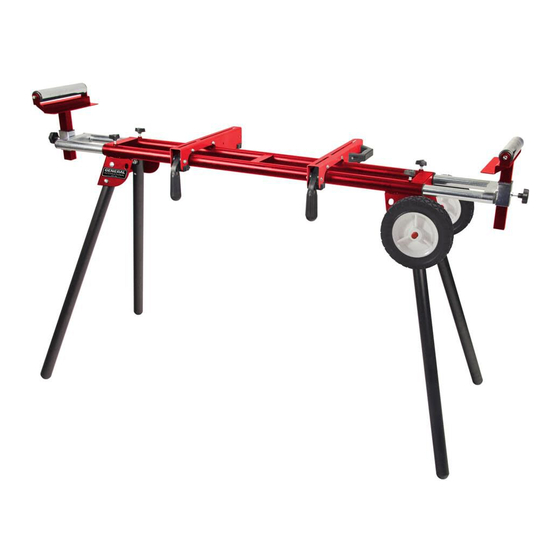
FEATURES
● Wheeled for convenient
transport
● Lightweight tubular steel
frame with strong 1-1/2
in. (38 mm) diameter
legs and dual crossbars
● Legs click and lock into
operating position
● Universal mounting
adaptors fit most saws
● Lever-actuated quick-
release saw mounting
system for easy
saw removal and
replacement
● Height-adjustable
support extensions
equipped with handy
material cutting stops
and rollers
SpEciFicATionS
● Dimensions (retracted
length): 47" – (extended
length): 79" x 25" x 35"
(1185 – 2000 x 632 x
900 mm)
● Height:
35", extendable to 39"
(900 mm to 987 mm)
● Load capacity:
330 lb. (150 kg)
● net weight:
36 lb. (16 kg)
General International Power Products, LLC
6243 Industrial Parkway
Whitehouse, OH 43571 USA
General International Power Products Ltd.
117-6741 Cariboo Rd.
Burnaby, BC V3N 4A3 Canada
website: www.gipowerproducts.com
SETUP & OPERATION MANUAL
Miter Saw Stand
Model#
MS3102 man v.150326
MS3102
Advertisement
Table of Contents

Related Manuals for General International MS3102


Summary of Contents for General International MS3102
-
Page 1: Specifications
● Load capacity: 330 lb. (150 kg) ● net weight: 36 lb. (16 kg) Model# MS3102 General International Power Products, LLC 6243 Industrial Parkway Whitehouse, OH 43571 USA General International Power Products Ltd. 117-6741 Cariboo Rd. Burnaby, BC V3N 4A3 Canada website: www.gipowerproducts.com... -
Page 2: Year Limited Warranty
2-year warranty period, subject to the “conditions and exceptions” as listed below. Repairs made without the written consent of General International will void the warranty. - Page 3 Because we are committed to making constant improvements, General International reserves the right to make changes to components, parts or features of this unit as...
- Page 4 CONDITIONS AND EXCEPTIONS This coverage is extended to the original purchaser only. prior warranty registration is not required but documented proof of purchase, i.e. a copy of original sales invoice or receipt showing the date and location of the purchase as well as the purchase price paid, must be provided at the time of claim.
-
Page 5: Important Safety Instructions
IMPORTANT SAFETY INSTRUCTIONS The purpose of safety symbols is to attract your attention to possible hazards. The safety symbols, and the explanations with them, deserve your careful attention and understanding. The safety warnings do not, by themselves, eliminate any danger. The instructions or warnings they give are not substitutes for proper accident prevention measures. - Page 6 IMPORTANT SAFETY INSTRUCTIONS READ ALL instructions before using this product. We strongly recommend that this tool not be modified and/or used for any application other than that for which it was designed. If you have any questions relative to its application, do not use the equipment until you have consulted us and we have advised you.
- Page 7 STAND-SPECIFIC SAFETY INSTRUCTIONS 1. TO OBTAIN MAxIMUM STABILITY, use the miter saw stand on a flat surface ONLY. 2. BE CAREfUL WHILE RAISINg AND LOWERINg THE STAND to prevent pinching your fingers or hands. 3. BE SURE THE SNAP BUTTONS ON EACH LEg ARE IN THE LOCKED POSITION before beginning work to ensure the stand remains rigid during cutting.
-
Page 8: Package Contents
PACKAGE CONTENTS Before starting assembly, please read all assembly instructions and familiarize yourself with the pieces you will be working with (fig.1). Refer also to the diagrams after the parts list for descriptions, quantities, and pieces included. fig.1 Item Description Qty. -
Page 9: Assembly Instructions
ASSEMBLY INSTRUCTIONS once you have confirmed that you have all the pieces required for assembly, you may begin. 1. With the main frame (A) upside down, unfold the legs (fig 2-1). Be sure the snap buttons on each leg are in the locked position. - Page 10 ATTACHING THE wHEELS TO THE STAND 7. Following fig 2-5, attach the wheels to the axle (I); first, place a C-clip (H) onto the axle, followed by a wheel (J), then secure it with another C-clip (fig 7). 8. Still referring to fig 2-5 & 7, bolt the axle/ wheel assembly to the end of the frame.
- Page 11 3. From your 2 front mounting points (fig 9, grey), measure at a 90 degree angle back to a point that is equal to your rear mounting point. NOTE: This distance cannot exceed 14 inches (35.6 cm) from the front mount. Example of a skewed Example of a skewed rear mounting point...
- Page 12 7. Secure your remaining miter saw mounting point(s) to the adaptor plate with an appropriate bolt assembly comprising a bolt of proper length, flat washer, lock washer, and lock nut. NOTE: The bolt assembly for this step must be supplied by the end user. SET-UP / KNOCK DOwN PROCEDURES ●...
-
Page 13: Caractéristiques
330 lb (150 kg) ● Poids net : Modèle # MS3102 36 lb (16 kg) General International Power Products, LLC 6243 Industrial Parkway Whitehouse, OH 43571 USA General International Power Products Ltd. 117-6741 Cariboo Rd. Burnaby, BC V3N 4A3 Canada site Web : www.gipowerproducts.com... - Page 14 NOUS VOUS REMERCIONS d’avoir choisi une machine de General International. Cette machine a été soigneusement testée et inspectée avant de vous être expédiée, et moyennant une utilisation et un entretien adéquats, elle vous procurera un service fiable pendant de nombreuses années. Afin d’obtenir un rendement optimal et une utilisation sans problème, et d’optimiser votre investissement, veuillez prendre le temps de lire ce manuel...
- Page 15 En raison de son souci d’amélioration constante, General International se réserve le droit de modifier des composantes, des pièces ou des caractéristiques de la machine si cela est jugé...
- Page 16 à General International, ou encore à un ® distributeur, un centre de réparation ou tout autre emplacement situé près de chez vous et désigné par General International. Pour plus ® d’informations ou si vous avez besoin d’aide pour remplir une demande de réclamation, contactez notre département de service.
-
Page 17: Consignes De Sécurité Importantes
LISEZ TOUTES LES INSTRUCTIONS AVANT L’UTILISATION CONSERVEZ CES INSTRUCTIONS Avant d’essayer de faire fonctionner votre nouvel outil, veuillez lire les instructions au complet. Vous aurez besoin de ces instructions pour les avertissements de sécurité, les précautions, l’assemblage, le fonctionnement, les procédures d’entretien, la liste des pièces et les schémas des pièces. - Page 18 3. ÉLOIGNEZ LES ENFANTS ET LES SPECTATEURS. Aucun enfant ne devrait se trouver dans l’espace de travail. ne les laissez pas manipuler les machines, les outils ou les rallonges électriques. Les visiteurs peuvent vous distraire et il est difficile de les prémunir contre les blessures.
- Page 19 3. ASSUREZ-VOUS qUE LES BOUTONS- PRESSION SUR ChAqUE PATTE SOIENT EN POSITION BLOqUÉE avant de commencer vos travaux afin d’assurer que le support demeure solidement en place. 4. NE PAS MARChER OU MONTER SUR LE SUPPORT EN AUCUN CAS. Ceci pourrait causer des dommages au support et/ou des blessures corporelles.
- Page 20 CONTENU DE LA BOÎTE Avant de commencer l’assemblage, veuillez lire toutes les directives et vous familiariser avec les pièces. Consultez le diagramme (fig.1) suivant la liste des pièces. Vous y trouverez la description, la quantité et les pièces incluses. fig.1 Pièce Description qté.
- Page 21 ASSEMBLAGE Après vous être assuré de disposer de toutes les pièces requises, vous pouvez procéder à l’assemblage. 1. Avec le cadre principal (A) la tête en bas, déplier les pattes (fig 2-1). Assurez-vous que les boutons pression sur chaque patte sont dans la position verrouillée.
- Page 22 fIXATION DES ROUES AU SUPPORT 4. En suivant les figures fig 2-5, fixer les roues à l’essieu (I), placer d’abord une attache en C (H) sur la l’essieu, suivie par une roue (J), puis fixez-le avec une autre attache en C (figure 7).
- Page 23 de votre scie à onglets, tel qu’illustré ci- dessous (fig.9). 2. S’assurer de laisser 1/2 po (15 mm) supplémentaire autour du rebord de la pièce. 3. À partir de vos 2 points d’assemblage, (gris en fig 9) mesurer un angle de 90 degrés, en reculant vers un point équivalent à...
- Page 24 6. Vous pouvez désormais fixer la plaque adaptatrice et la scie à onglets au rail d’assemblage de la scie. La plaque adaptatrice se place entre le fond de la scie à onglets et le dessus du rail d’assemblage de la scie. 7.
Need help?
Do you have a question about the MS3102 and is the answer not in the manual?
Questions and answers