Table of Contents
Advertisement
SETUP & OPERATION MANUAL
FEATURES
Sturdy welded steel frame & precision balanced
wheels with replaceable tires.
Sturdy closed base steel stand.
Deluxe blade guide bearings included.
Precision metal miter gauge.
Two cutting speeds for excellent results in either
hard or soft woods.
Deluxe dual-position rip fence system.
Hinged doors and easily accessible blade
tension knob, for fast blade changes and
adjustments.
Extra-large 21 1/2" x 15 3/4" cast-iron table.
Smooth running heavy-duty 1 HP motor.
Safety lock-out switch with removable key to
prevent unauthorized use.
SPECIFICATIONS
• Wheel size
14" (350 mm)
• Wheel speeds (2)
436 & 909 rpm
• Blade speeds (2)
1575 & 3280 lin. fpm
• Maximum blade width
3/4" (19 mm)
• Minimum blade width
1⁄8" (3 mm)
• Blade length
100 3/4" (2560 mm)
• Table size
21 1/2" x 15 3/4" (548 x 400 mm)
• Table tilt
0° to 45° (right)
• Table height
39 3/8" (950 mm)
• Maximum width of cut
13 3/8" (340 mm)
• Maximum depth of cut
9" (230 mm)
• Dust port
4" (102 mm)
• Base dimensions (l x w)
22 7/8" x 17 3/8" (580 x 440 mm)
• Motor
1 HP , 120 V, 9.5 A
• Weight
194 lbs (88 kg)
Version
1_Revision
3 - March 2016
#
#
© Copyright General International
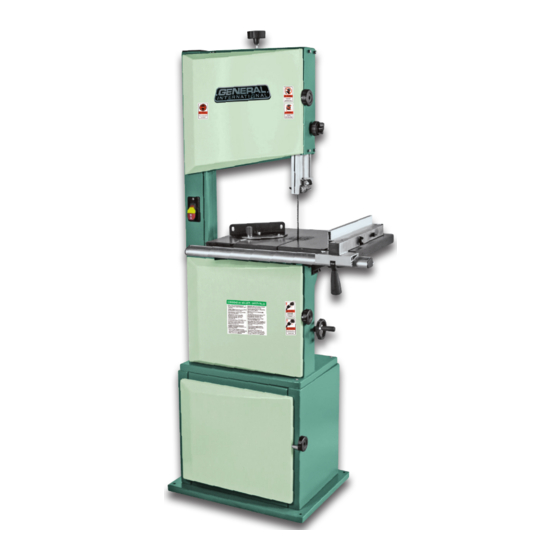
14" WOOD CUTTING BANDSAW
MODEL
90-120
#
Advertisement
Table of Contents

Related Manuals for General International 90-120


Summary of Contents for General International 90-120
- Page 1 • Base dimensions (l x w) 22 7/8” x 17 3/8” (580 x 440 mm) • Motor 1 HP , 120 V, 9.5 A 90-120 • Weight 194 lbs (88 kg) Version 1_Revision 3 - March 2016 © Copyright General International...
- Page 2 Telephone (514) 326-1161 • Fax (514) 326-5555 • www.general.ca THANK YOU for choosing this General® International model 90-120 14” Wood Cutting Bandsaw. This bandsaw has been carefully tested and inspected before shipment and if properly used and maintained, will provide you with years of reliable service.
- Page 3 GENERAL INTERNATIONAL WARRANTY ® All component parts of General International and Excalibur by General International products ® ® are carefully inspected during all stages of production and each unit is thoroughly inspected upon completion of assembly. Limited Lifetime Warranty Because of our commitment to quality and customer satisfaction, General International agrees to ®...
-
Page 4: Table Of Contents
TABLE OF CONTENTS Rules for safe operation ..................... 5 Electrical requirements ...................... 6 Identification of main parts and components ..............7 Unpacking .......................... 8 Basic functions ........................9 Cleaning..........................9 Placement within the shop ....................9 Assembly instructions ....................10 - 14 Assembling the cabinet .......................... -
Page 5: Rules For Safe Operation
RULES FOR SAFE OPERATION To help ensure safe operation, please take a moment to learn the machine’s applications and limitations, as well as potential hazards. General International disclaims any real or implied warranty and holds itself ® harmless for any injury that may result from the improper use of it’s equipment. 1. -
Page 6: Electrical Requirements
ELECTRICAL REQUIREMENTS BEFORE CONNECTING THE MACHINE TO THE POWER SOURCE, VERIFY THAT THE VOLTAGE OF YOUR POWER SUP- PLY CORRESPONDS WITH THE VOLTAGE SPECIFIED ON THE MOTOR I.D. NAMEPLATE. A POWER SOURCE WITH GREATER VOLTAGE THAN NEEDED CAN RESULT IN SERIOUS INJURY TO THE USER AS WELL AS DAMAGE TO THE MACHINE. -
Page 7: Identification Of Main Parts And Components
IDENTIFICATION OF MAIN PARTS AND COMPONENTS BASE CABINET DOOR LOWER WHEEL DOOR RIP FENCE RAIL SWITCH WITH REMOVABLE KEY UPPER WHEEL DOOR BLADE TENSION KNOB UPPER DOOR LOCK KNOB BLADE GUARD LOCK KNOB BLADE GUARD ADJUSTMENT KNOB BLADE GUARD UPPER BLADE GUIDE MITER GAUGE BLADE RIP FENCE... -
Page 8: Unpacking
UNPACKING Carefully unpack and remove the unit and its components from the box and check for missing or damaged items as per the list of contents below. NOTE: PLEASE REPORT ANY DAMAGED OR MISSING ITEMS TO YOUR GENERAL® INTERNATIONAL DISTRIBUTOR IMMEDIATELY. LIST OF CONTENTS NUT ................... -
Page 9: Basic Functions
This 14” Wood Cutting Bandsaw is supplied with a 1/2” general purpose blade and is designed to accommodate blade widths from 1/8” to 3/4”. Ideal blade length for this model 90-120 is 100 3/4” (2560 mm). Note: Generally speaking, because the upper wheel height is somewhat adjustable (to allow for blade tensioning), a blade length variation of plus or minus 1/2”... -
Page 10: Assembly Instructions
ASSEMBLY INSTRUCTIONS BEFORE ASSEMBLING, MAKE SURE THAT THE SWITCH IS IN THE “OFF” POSITION AND THAT THE POWER CORD IS UNPLUGGED. DO NOT PLUG IN OR TURN ON THE MACHINE UNTIL YOU HAVE COMPLETED THE ASSEMBLY AND INSTALLATION STEPS DESCRIBED IN THIS SECTION OF THE MANUAL. ASSEMBLING THE CABINET Set the right panel on the base. -
Page 11: Attaching The Machine To The Cabinet
BEFORE ASSEMBLING, MAKE SURE THAT THE SWITCH IS IN THE “OFF” POSITION AND THAT THE POWER CORD IS UNPLUGGED. DO NOT PLUG IN OR TURN ON THE MACHINE UNTIL YOU HAVE COMPLETED THE ASSEMBLY AND INSTALLATION STEPS DESCRIBED IN THIS SECTION OF THE MANUAL. ASSEMBLING THE CABINET (CONTINUED) 10. -
Page 12: Installing The Table And The 90° Stop
BEFORE ASSEMBLING, MAKE SURE THAT THE SWITCH IS IN THE “OFF” POSITION AND THAT THE POWER CORD IS UNPLUGGED. DO NOT PLUG IN OR TURN ON THE MACHINE UNTIL YOU HAVE COMPLETED THE ASSEMBLY AND INSTALLATION STEPS DESCRIBED IN THIS SECTION OF THE MANUAL. INSTALLING THE TABLE AND THE 90°... -
Page 13: Installing The Rip Fence System
BEFORE ASSEMBLING, MAKE SURE THAT THE SWITCH IS IN THE “OFF” POSITION AND THAT THE POWER CORD IS UNPLUGGED. DO NOT PLUG IN OR TURN ON THE MACHINE UNTIL YOU HAVE COMPLETED THE ASSEMBLY AND INSTALLATION STEPS DESCRIBED IN THIS SECTION OF THE MANUAL. INSTALLING THE RIP FENCE Slide a washer onto each lock knob and loosely Fit the rail onto the lock knobs as shown. -
Page 14: Installing The Belt Tension Handwheel
BEFORE ASSEMBLING, MAKE SURE THAT THE SWITCH IS IN THE “OFF” POSITION AND THAT THE POWER CORD IS UNPLUGGED. DO NOT PLUG IN OR TURN ON THE MACHINE UNTIL YOU HAVE COMPLETED THE ASSEMBLY AND INSTALLATION STEPS DESCRIBED IN THIS SECTION OF THE MANUAL. INSTALLATING THE BELT TENSION HANDWHEEL Secure the handwheel in place by tightening the set Slide the handwheel on the arbor. -
Page 15: Choosing And Changing Blades
MAKE SURE THE MACHINE HAS BEEN TURNED OFF AND UNPLUGGED FROM THE POWER SOURCE BEFORE PERFORM- ING ANY MAINTENANCE OR ADJUSTMENTS. CHOOSING AND CHANGING THE BLADE There are a variety of different types of bandsaw blades on the BLADE SELECTION market to suit various cutting applications. -
Page 16: Adjusting Blade Tension
MAKE SURE THE MACHINE HAS BEEN TURNED OFF AND UNPLUGGED FROM THE POWER SOURCE BEFORE PERFORM- ING ANY MAINTENANCE OR ADJUSTMENTS. CHOOSING AND CHANGING THE BLADE (CONTINUED) RIGHT SIDE VIEW Release the blade tension by turning the tension le- To install a blade, repeat the previous steps in re- ver A to the right. -
Page 17: Ajusting Blade Tracking
MAKE SURE THE MACHINE HAS BEEN TURNED OFF AND UNPLUGGED FROM THE POWER SOURCE BEFORE PERFORM- ING ANY MAINTENANCE OR ADJUSTMENTS. ADJUSTING BLADE TRACKING Blade tracking means centering the blade on the wheels A. Ideally, the blade should stay relatively cen- tered on both the upper and lower wheels. -
Page 18: Adjusting The Upper Blade Guides
MAKE SURE THE MACHINE HAS BEEN TURNED OFF AND UNPLUGGED FROM THE POWER SOURCE BEFORE PERFORM- ING ANY MAINTENANCE OR ADJUSTMENTS. ADJUSTING THE UPPER BLADE GUIDES REAR VIEW 1/32" Loosen the two thumbscrews A. Adjust the guides by turning the knurled nut B so that the guides are at least 1/32”... -
Page 19: Adjusting The Upper Thrust Bearing
MAKE SURE THE MACHINE HAS BEEN TURNED OFF AND UNPLUGGED FROM THE POWER SOURCE BEFORE PERFORM- ING ANY MAINTENANCE OR ADJUSTMENTS. ADJUSTING THE LOWER THRUST BEARING 1/64" Loosen the set screw A located under the table us- Then manually adjust the thrust bearing bracket in ing a 3 mm Allen key. -
Page 20: Adjusting The Upper Blade Guard
MAKE SURE THE MACHINE HAS BEEN TURNED OFF AND UNPLUGGED FROM THE POWER SOURCE BEFORE PERFORM- ING ANY MAINTENANCE OR ADJUSTMENTS. SELECTING AND CHANGING THE BLADE SPEED (CONTINUED) 3280 pi/lin/min 1574 pi/lin/min MOTOR PULLEYS WHEEL PULLEYS 3280 pi/lin/min 1574 pi/lin/min POULIES DU MOTEUR POULIES DE LA ROUE Make sure the belt is properly installed on the pul-... -
Page 21: Operating Instructions
OPERATING INSTRUCTIONS CHECKLIST BEFORE STARTING VERIFY ALL CHECK POINTS BEFORE STARTING. FAILURE TO COMPLY CAN RESULT IN SERIOUS INJURIES. Make sure you and any assistants are wearing safe and appropriate workshop attire. To reduce the risk of damage to the machine, as well as potential for personal injury, after initial set-up as well as before each use, make sure that everything is securely installed and that all fasteners and moving parts on this machine are locked in place before starting the machine. -
Page 22: Using The Miter Gauge
MAKE SURE THE MACHINE HAS BEEN TURNED OFF AND UNPLUGGED FROM THE POWER SOURCE BEFORE PERFORM- ING ANY MAINTENANCE OR ADJUSTMENTS. USING THE MITER GAUGE Position the miter gauge on the table. Insert the miter gauge into the “T” slot in the table as shown. -
Page 23: Changing The Belt And Aligning The Pulleys
MAKE SURE THE MACHINE HAS BEEN TURNED OFF AND UNPLUGGED FROM THE POWER SOURCE BEFORE PERFORM- ING ANY MAINTENANCE OR ADJUSTMENTS. CHANGING THE BELT AND ALIGNING THE PULLEYS Loosen the belt, remove the retention ring, then re- Release blade tension by turning the tension lever move the wheel and the used belt. -
Page 24: Parts List & Diagram
DIAGRAM CABINET IMPORTANT: When ordering replacement parts, always give the model number, serial number of the machine and part number. Also a brief description of each item and quantity desired. PART # DESCRIPTION SPECIFICATIONS 90120C-01 LEFT PANEL 90120C-02 THREADED INSERT M6 X 13.5 90120C-03 CROSS BRACE... - Page 25 DIAGRAM BANDSAW...
- Page 26 PARTS LIST BANDSAW IMPORTANT: When ordering replacement parts, always give the model number, serial number of the machine and part number. Also a brief description of each item and quantity desired. PART DESCRIPTION SPECIFICATIONS 90120-01 LOWER DOOR 90120-02 CAP SCREW M6 X 16 90120-03 SLEEVE...
- Page 27 PARTS LIST BANDSAW IMPORTANT: When ordering replacement parts, always give the model number, serial number of the machine and part number. Also a brief description of each item and quantity desired. PART DESCRIPTION SPECIFICATIONS 90120-48 BEARING 6202Z 90120-49 SHAFT 90120-50 SWITCH 90120-51 ECCENTRIC WHEEL...
- Page 28 PARTS LIST BANDSAW IMPORTANT: When ordering replacement parts, always give the model number, serial number of the machine and part number. Also a brief description of each item and quantity desired. PART DESCRIPTION SPECIFICATIONS 90120-95 TABLE 90120-96 TABLE INSERT 90120-97 WING NUT 90120-98 END CAP...
- Page 29 NOTES...
-
Page 30: Contact Information
8360 Champ-d’Eau, Montreal (Quebec) Canada H1P 1Y3 Tel.: (514) 326-1161 Fax: (514) 326-5565 - Parts & Service / (514) 326-5555 - Order Desk orderdesk@general.ca www.general.ca Follow us:...
Need help?
Do you have a question about the 90-120 and is the answer not in the manual?
Questions and answers
We are looking for a part to repair the saw, P/N 90120-51. Do you have this parts and can you sell it ? Or where i could buy it ? Thank you.