Table of Contents
Advertisement
Quick Links
Advertisement
Chapters
Table of Contents
Troubleshooting

Related Manuals for Canon iPF760 series


Summary of Contents for Canon iPF760 series
-
Page 1: Service Manual
Service Manual iPF760/750 series Jul 25 2012... - Page 3 Canon will release technical information as the need arises. In the event of major changes in the contents of this manual over a long or short period, Canon will issue a new edition of this manual.
-
Page 4: Symbols Used
Introduction Symbols Used This documentation uses the following symbols to indicate special information: Symbol Description Indicates an item of a non-specific nature, possibly classified as Note, Caution, or Warning. Indicates an item requiring care to avoid electric shocks. Indicates an item requiring care to avoid combustion (fire). Indicates an item prohibiting disassembly to avoid electric shocks or problems. - Page 5 Introduction The following rules apply throughout this Service Manual: 1. Each chapter contains sections explaining the purpose of specific functions and the relationship between electrical and mechanical systems with refer- ence to the timing of operation. In the diagrams, represents the path of mechanical drive; where a signal name accompanies the symbol , the arrow indicates the direction of the electric signal.
-
Page 7: Table Of Contents
Contents Contents Chapter 1 PRODUCT DESCRIPTION 1.1 Product Overview ............................1- 1 1.1.1 Product Overview ..............................1- 1 1.2 Features ..............................1- 2 1.2.1 Features .................................. 1- 2 1.2.2 Features .................................. 1- 2 1.2.3 Features .................................. 1- 2 1.2.4 Features .................................. 1- 2 1.2.5 Printhead ................................. - Page 8 Contents 1.7.3.4 Precautions for Disassembly/Reassembly..........................1- 71 1.7.3.5 Self-diagnostic Feature ................................1- 71 1.7.3.6 Disposing of the Lithium Battery ............................1- 72 Chapter 2 TECHNICAL REFERENCE 2.1 Basic Operation Outline ..........................2- 1 2.1.1 Printer Diagram................................2- 1 2.1.2 Printer Diagram................................2- 2 2.1.3 Print Signal Sequence .............................2- 3 2.1.4 Print Driving ................................2- 4 2.2 Firmware ..............................
- Page 9 Contents Chapter 3 INSTALLATION 3.1 Transporting the Printer ..........................3- 1 3.1.1 Transporting the Printer............................3- 1 3.1.1.1 Transporting the Printer ................................3- 1 3.1.2 Reinstalling the Printer ............................3- 3 3.1.2.1 Reinstalling the Printer................................3- 3 Chapter 4 DISASSEMBLY/REASSEMBLY 4.1 Service Parts ..............................4- 1 4.1.1 Service Parts ................................
- Page 10 Contents 6.2.1 Main controller PCB ..............................6- 1 6.2.2 Carriage PCB................................6- 8 6.2.3 Power supply .................................6- 12 6.3 Version Up..............................6- 13 6.3.1 Firmware Update Tool ............................6- 13 6.4 Service Tools............................6- 17 6.4.1 Tool List .................................6- 17 Chapter 7 SERVICE MODE 7.1 Service Mode .............................
-
Page 11: Chapter 1 Product Description
Chapter 1 PRODUCT DESCRIPTION... - Page 13 Contents Contents 1.1 Product Overview ................................1-1 1.1.1 Product Overview ..................................1-1 1.2 Features ..................................1-2 1.2.1 Features ......................................1-2 1.2.2 Features ......................................1-2 1.2.3 Features ......................................1-2 1.2.4 Features ......................................1-2 1.2.5 Printhead ...................................... 1-3 1.2.6 Ink Tank ....................................... 1-3 1.2.7 Cutter......................................1-3 1.2.8 Roll Holder....................................
- Page 14 Contents 1.7.3.5 Self-diagnostic Feature ....................................1-71 1.7.3.6 Disposing of the Lithium Battery ................................. 1-72...
-
Page 15: Product Overview
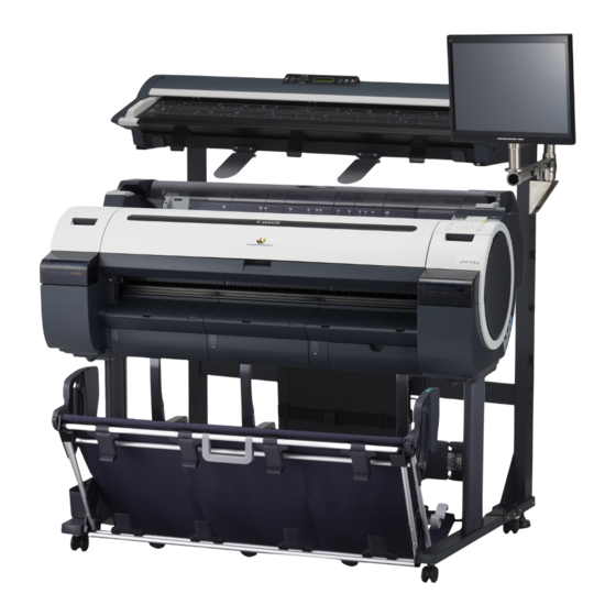
Chapter 1 1.1 Product Overview 1.1.1 Product Overview 0023-1254 iPF765 / iPF760 / iPF750 / iPF755 This printer is capable of printing on A4- to A0-size cut sheets and its maximum print width is 36 inches. This printer is a desktop large-format printer five-colors (dye- and pigment-based colors) printer that can be used to print CAD and office documents as well as handy POP and posters. -
Page 16: Features
Chapter 1 1.2 Features 1.2.1 Features 0023-1255 iPF755 - High resolutions of 2,400 x 1,200 dpi maximum, coupled with the exceptionally light-fast, water-proof and ozone-proof five-color pigment inks of Y, M, C, PBK and MBK, deliver high-quality photographic picture quality. - Black ink suitable for the selected media type is automatically selected from two types of black ink, "black ink"... -
Page 17: Printhead
Chapter 1 and MBK, deliver high-quality photographic picture quality. - Black ink suitable for the selected media type is automatically selected from two types of black ink, "black ink" for vivid and glossy printing and "matte black ink" for matte and high-quality printing. - A 160-by-128-dot-large LCD - One-inch wide printhead having 2,560 nozzles per color, which are as many as the those of the existing models. - Page 18 Chapter 1 The roller holder accepts paper tubes having inside diameters of both 2 and 3 inches. It is furnished with attachments for 2- and 3-inch diameter paper tubes. The roll holder clamps the paper tube of a roll not exceeding 150 mm in outside diameter from the inside. F-1-5 [2-inch paper tube attachment] F-1-6...
-
Page 19: Stand (St-33)
Chapter 1 1.2.9 Stand (ST-33) 0023-1260 iPF750 / iPF755 The stand [1] is equipped with casters so that the printer can be easily moved. The output stacker [2] included with stand can use by the two ways of the regular position or extended position. - Page 20 Chapter 1 [Extended position] F-1-12 - Changing from the regular position to extended position. 1) Raise the auxiliary rod [1] to the position [A] of the illustration to change to the extended position. F-1-13 2) Pull out the switching stopper [1] when using roll paper that is A1 size or has a width of 24 inches. F-1-14...
-
Page 21: Stand (St-34)
Chapter 1 1.2.10 Stand (ST-34) 0027-2228 iPF765 / iPF760 / iPF750 / iPF755 The stand [1] is equipped with casters so that the printer can be easily moved. The output stacker [2] included with stand can use by the three ways of the regular position or two extended positions. - Page 22 Chapter 1 [Extended position A] F-1-18 - Changing from the regular position to extended position A. 1) Raise the auxiliary rod [1] to the position [A] of the illustration to change to the extended position A. F-1-19 2) Pull out the switching stopper [1] when using roll paper that is A1 size or has a width of 24 inches. F-1-20 [Extended position B] F-1-21...
- Page 23 Chapter 1 - Changing from the regular position to extended position B. 1) Grasp the output stacker handle [1] to set the guide as shown in the following illustration. F-1-22 2) Open the output stacker ejection guides [1] toward the front. F-1-23 - Changing from the extended position B to regular position.
-
Page 24: Hard Disk Drive
Chapter 1 1.2.11 Hard Disk Drive 0017-8472 iPF765 / iPF755 Each print job received from the host computer is saved to the hard disk drive(serial ATA connection) attached to the printer, so the printer can print the job repeat- edly as needed, without having to wait for its retransmission from the host computer. Saving print jobs will offer the following benefits: - Eased computer workload A print job may be automatically preserved to the hard disk when printing or may be preserved to the hard disk without printing. -
Page 25: Product Specifications
Chapter 1 1.3 Product Specifications 1.3.1 Product Specifications 0023-1273 iPF755 Type Bubble jet large-sized paper printer (stand model) Feeding system Roll media: manual feed from top Cut sheet: manual feed from top Feeding capacity - Roll media: 1 roll madia (Outer diameter of roll: 150 mm or less/Inner diameter of paper tube: 2 or 3 inches) - Cut sheet: 1 sheet Delivery method... -
Page 26: Product Specifications
Chapter 1 Interface USB2.0 Hi-Speed Network (10Base-T/100Base-TX/1000Base-T) Operation panel LCD (160 X 128 dots), 13 keys, 5 LEDs - Panel language English - Message language English, German, French, Italian, Spanish, Chinese, Korean, Russianand and Japanese Printhead/Ink Tank type Printhead and separate ink tanks Printhead PF-04 Structure: Integrated six-color assembly... - Page 27 Chapter 1 Type of media Roll Media: Plain Paper, Plain Paper (High Quality), Plain Paper (High Grade), Coated Paper, Heavyweight Coated Paper, Premium Matte Paper, Premium Glossy Paper 200, Premium Semi-Glossy Paper 200, Premium Glossy Paper 280, Premium Semi-Glossy Paper 280, Back Light Film, Economy Bond Paper, Universal Bond Paper, Matte Coated Paper 170gsm, Premium RC Photo Luster, Durable Backlit Film, High Resolution Coated Paper, Matte Coated Paper 90gsm, Glossy...
- Page 28 Chapter 1 Detection functions (Carriage Printhead presence/absence detection: Yes system) Carriage position detection: Yes Carriage home position detection: Yes Printhead temperature detection: Yes Printhead height detection: Yes Non-discharging nozzle detection: Yes Non-discharging nozzle backup feature: Yes Ambient temperature/humidity detection: Yes Detection functions (Paper path Paper presence/absence detection: Yes system)
- Page 29 Chapter 1 Supported thickness 0.07mm to 0.8mm Media size (Roll media) Width: 254.0mm (10") to 914.4mm (36") Length: 203.2mm (8") to 18m (709") *1 Outer diameter of roll :150mm or less *1: The maximum amount of length may vary by the using operating system or the applications.
- Page 30 Chapter 1 Power consumption In power save (sleep) mode: 100-120 VAC : 5W or less 220-240 VAC : 6W or less During standby: 0.5W or less Printer unit dimensions 1304mm(W) x 887mm(D) x 1062mm(H) (with ST-34 stand and opening (WxDxH) the output stacker) 1304mm(W) x 1100mm(D) x 1062mm(H) (with ST-34 stand and setting to the extended position B)
-
Page 31: Detailed Specifications
Chapter 1 Memory 256MB Increase of memory: none Firmware Flash ROM (update from USB or Ethernet) - Printer description language GARO (Graphic Arts language with Raster Operation), HP-GL/2, HP- Interface USB2.0 Hi-Speed Network (10Base-T/100Base-TX/1000Base-T) Operation panel LCD (160 X 128 dots), 13 keys, 5 LEDs - Panel language English - Message language... - Page 32 Chapter 1 (5) Interface connector Printer side: Series B receptacle compliant with USB standard Cable side: Series B plug compliant with USB standard b. Network (standard) (1) Interface type Interface compliant with IEEE802.3 (2) Data transfer system IEEE802.0 10Base-T, IEEE802.3u 100Base-TX/Auto-Negotiation, IEEE802.3ab 1000Base-T/Auto-Negotiation, IEEE802.3x Full Duplex (3) Interface cable Category 5 (UTP or FTP) cable, 100 m or shorter Compliant with ANSI/EIA/TIA-568A or ANSI/EIA/TIA-568B...
-
Page 33: Names And Functions Of Components
Chapter 1 1.5 Names and Functions of Components 1.5.1 Front 0023-1263 iPF765 / iPF760 / iPF750 / iPF755 [14] [15] [13] [16] [12] [11] [10] F-1-28 [1] Roll media cover Open this cover, and then load roll media. [2] Media loading slot Insert media in this slot to load it. -
Page 34: Side
Chapter 1 1.5.2 Side 0023-1264 iPF765 / iPF760 / iPF750 / iPF755 F-1-29 [1] Manual pocket Store the printer manual in this pocket. [2] Ethernet connector Connect the Ethernet cable to this connector. The lamp lights when the Ethernet cable is connected properly and the printer is ready to communicate accordingly. [3] USB port Connect the USB cable to this port. -
Page 35: Top Cover (Inside)
Chapter 1 1.5.3 Top Cover (Inside) 0023-1265 iPF765 / iPF760 / iPF750 / iPF755 F-1-30 [1] Carriage The carriage moves the printhead. It is an important component used for printing. [2] Carriage shaft The carriage moves on this shaft. [3] Paper retainer This is an important component used to feed paper. -
Page 36: Roll Unit Cover (Inside)
Chapter 1 1.5.4 Roll Unit Cover (Inside) 0023-1266 iPF765 / iPF760 / iPF750 / iPF755 F-1-31 [1] Roll holder Load roll media in this holder. [2] Holder stopper Use this part to secure roll media to the roll holder. [3] Slide guide Move the roll holder along this guide. -
Page 37: Ink Tank Cover (Inside)
Chapter 1 1.5.6 Ink Tank Cover (Inside) 0023-1268 iPF765 / iPF760 / iPF750 / iPF755 [Left Ink Tank Unit] F-1-33 [Right Ink Tank Unit] F-1-34 [1] Ink tank lock lever This lever is used to protect and lock the ink tank. Open/close this lever when replacing the ink tank. [2] Ink color label Load each ink tank according to the label color and name. -
Page 38: Stand (St-33)
Chapter 1 1.5.7 Stand (ST-33) 0023-1269 iPF750 / iPF755 F-1-35 [1] Accessory pocket Store the printer accessories. [2] Output stacker Ejected printouts are collected in this output stacker. [3] Lockable caster This caster can be locked. When relocating the printer, be sure to unlock all four casters. Moving the printer with the casters locked can damage the floor. [4] Switching stopper Pull out this stopper when using the output stacker at the extended position. -
Page 39: Stand (St-34)
Chapter 1 1.5.8 Stand (ST-34) 0027-2234 iPF765 / iPF760 / iPF750 / iPF755 O F F F-1-36 [1] Accessory pocket Store the printer accessories. [2] Output stacker Ejected printouts are collected in this output stacker. [3] Lockable caster This caster can be locked. When relocating the printer, be sure to unlock all four casters. -
Page 40: Basic Operation
Chapter 1 1.6 Basic Operation 1.6.1 Operation Panel 0023-1270 iPF765 / iPF760 / iPF750 / iPF755 This section explains the functions of the buttons and the meanings of the LEDs on the operation panel. [15] Data [14] Message [13] [12] Power Load Feed Cut... -
Page 41: Display
Chapter 1 1.6.2 Display 0023-1271 iPF765 / iPF760 / iPF750 / iPF755 When the printer starts, the [tab selection screen] appears on the display. There are four types of tabs on which the relevant printer status, menu, and error information are displayed. The tab appears as the icon to the top field of display. -
Page 42: Menu
Chapter 1 1.6.3 Menu 0027-9452 iPF765 / iPF760 The printer has a Main menu which includes a menu related to maintenance such as adjustment of ink ejection position of each nozzle and head cleaning, a menu related to printing settings such as auto cutting and ink drying time, and a menu related to parameters such as a message language. 1. - Page 43 Chapter 1 2. Main Menu The structure and settings of the main menu is as follows. The asterisk mark "*" is default setting. [Paper Menu] First Level Second Level Third Level Fourth Level Fifth Level [Load Paper] [Roll Paper] [Cut Sheet] [Eject Paper] [Chg.
- Page 44 Chapter 1 First Level Second Level Third Level Fourth Level Fifth Level [Paper Details] (The paper type is displayed [Scan Wait Time] [Dry time] [Off]* here.) [1 sec.] [3 sec.] [5 sec.] [7 sec.] [9 sec.] [Area]*16 [Entire area] [Leading edge] [Roll DryingTime] [Off] [30 sec.]...
- Page 45 Chapter 1 [Ink Menu] First Level Second Level Third Level Fourth Level Fifth Level [Rep. Ink Tank] [Head Cleaning A] [Job Menu] First Level Second Level Third Level Fourth Level Fifth Level [Print Job]*14 [Job List] (Select Print Job.) [Delete] [Preempt Jobs]*3 [Stored Job]*14 [Mailbox List]...
- Page 46 Chapter 1 [Set./Adj. Menu] First Level Second Level Third Level Fourth Level Fifth Level [Test Print] [Nozzle Check] [Status Print] [Interface Print] [GL2 Set Print] [Paper Details] [Print Job Log] [Menu Map] [Color Palette] [Adjust Printer] [Head Posi. Adj.] [Auto(Standard)] [Auto(Advanced)] [Manual]*4 [Head Inc.
- Page 47 Chapter 1 First Level Second Level Third Level Fourth Level Fifth Level Sixth Level [GL2 Settings] [Paper Manager] [Paper Source] [Automatic]* [Roll Paper] [Cut Sheet] [Margin] [3mm(Standard)]* [5mm] [Conserve Paper] [Off]* [On] [Auto Rotate] [Off]* [On] [Nesting]*14 [Use Nesting] [Off]* [On] [Nesting WaitTime]*7 [xx min.] [Cut Lines]*7...
- Page 48 Chapter 1 First Level Second Level Third Level Fourth Level Fifth Level Sixth Level Seventh Level [Interface Setup] [EOP Timer]*12 [10 sec.] [30 sec.] [1 min.] [2 min.] [5 min.] [10 min.]* [30 min.] [60 min.] [TCP/IP]*12 [IPv4] [IPv4 Mode] [Automatic] [Manual]* [Protocol]*8...
- Page 49 Chapter 1 First Level Second Level Third Level Fourth Level Fifth Level [Interface Setup] [AppleTalk]*12 [On] [Off]* [Ethernet Driver]*12 [Auto Detect] [On]* [Off] [Comm.Mode]*10 [Half Duplex]* [Full Duplex] [Ethernet Type]*10 [10Base-T]* [100Base-TX] [1000Base-T] [Spanning Tree] [Not Use]* [Use] [MAC Address] xxxxxxxxxxxx [Interface Print]*12 [Return Defaults]*12...
- Page 50 Chapter 1 First Level Second Level Third Level Fourth Level Fifth Level [System Setup] [Time Zone]*12 [0:London(GMT)] [+1:Paris,Rome] [+2:Athens,Cairo] [+3:Moscow] [+4:Eerevan,Baku] [+5:Islamabad] [+6:Dacca] [+7:Bangkok] [+8:Hong Kong] [+9:Tokyo,Seoul] [+10:Canberra] [+11NewCaledonia] [+12:Wellington] [-12:Eniwetok] [-11:Midway is.] [-10Hawaii(AHST)] [-9:Alaska(AKST)] [-8:Oregon (PST)] [-7:Arizona(MST)] [-6:Texas(CST)] [-5:NewYork(EST)] [-4:Santiago] [-3:Buenos Aires] [-2:]...
- Page 51 Chapter 1 First Level Second Level Third Level Fourth Level Fifth Level [System Setup] [Nozzle Check] [Frequency] [Standard]* [1 page] [Warning] [Off]* [On] [Use USB]*12 [On]* [Off] [Use Ethernet]*12 [On]* [Off] [Use RemoteUI]*12 [On]* [Off] [Reset PaprSetngs]*12 [Erase HDD Data]*14 [High Speed]*12 [Secure High Spd.]*12 [Secure]*12...
- Page 52 Chapter 1 3. Main menu during printing The structure of the main menu during printing is as follows. First Level Second Level Third Level Fourth Level Fifth Level [Adj. Fine Feed] [Printer Info] [Paper Info] [Ink Info] [Head Info] [System Info] [Error Log] [Other Counter] 1-38...
- Page 53 Chapter 1 4. Main Menu Settings Main menu items are described in the following tables. [Paper Menu] Setting Item Description/Instructions [Load Paper] Select and load either cut sheet or roll media. [Eject Paper] Remove currently loaded paper. [Chg. Paper Type] Change currently set paper type.
- Page 54 Chapter 1 [Ink Menu] Setting Item Description/Instructions [Rep. Ink Tank] When replacing the Ink Tank, choose Yes and follow the instructions on the screen. [Head Cleaning A] Specify Printhead cleaning options. Execute Head Cleaning A if printing is faint, oddly colored, or contains foreign substances. [Job Menu] Setting Item Description/Instructions...
- Page 55 Chapter 1 [Set./Adj. Menu] Setting Item Description/Instructions [Test Print] [Nozzle Check] Print a nozzle check pattern. [Status Print] Print the printer information. [Interface Print] Print the interface settings. [GL2 Set Print] Print the GL2 settings. [Paper Details] Prints the paper settings set with [Paper Details]. [Print Job Log] Print print job information such as paper type, size, and ink consumption.
- Page 56 Print by the standard color. [Color (CAD) 2] Print by the bright color. [Color (CAD) 3] Print by the color emulated the Canon iPF500/iPF600/iPF700/iPF510/iPF610/iPF710/iPF605/ iPF720/iPF810/iPF820. [Color (CAD) 4] Print by the color emulated the HP Designjet 500/800. [Color (CAD) 5] Print by the color emulated the HP Designjet 1000.
- Page 57 Chapter 1 Setting Item Description/Instructions [Interface [EOP Timer] Specify the timeout period before cancellation of print jobs that cannot be Setup] received by the printer. [TCP/IP] [IPv4] [IPv4 Mode] Choose whether the printer IP address is configured automatically or a static IP address is entered manually.
- Page 58 Chapter 1 Setting Item Description/Instructions [System Setup] [Sleep Timer] Specify the period before the printer enters Sleep mode. [Shut Down Timer] Specify the period the printer shuts down after entering Sleep mode. [Buzzer] Set the buzzer. Choose On for the buzzer to sound once for warnings and three times for errors. [Contrast Adj.] Adjust the Display Screen contrast level.
- Page 59 Chapter 1 Setting Item Description/Instructions [System Setup] [Erase HDD Data] [High Speed] Delete the file management information of the saved data in the HDD. [Secure High Spd.] Overwrite the random data in the whole of the hard disk drive. [Secure] Overwrite 00 and FF and random data in the whole of the hard disk drive once at a time.
-
Page 60: Menu
Chapter 1 1.6.4 Menu 0023-2460 iPF750 / iPF755 The printer has a Main menu which includes a menu related to maintenance such as adjustment of ink ejection position of each nozzle and head cleaning, a menu related to printing settings such as auto cutting and ink drying time, and a menu related to parameters such as a message language. 1. - Page 61 Chapter 1 2. Main Menu The structure and settings of the main menu is as follows. The asterisk mark "*" is default setting. [Paper Menu] First Level Second Level Third Level Fourth Level Fifth Level [Load Paper] [Roll Paper] (The paper type is displayed here.) [Cut Sheet] (The paper type is displayed...
- Page 62 Chapter 1 First Level Second Level Third Level Fourth Level Fifth Level [Paper Details] (The paper type is displayed [Scan Wait Time] [Dry time] [Off] here.) [1 sec.] [3 sec.] [5 sec.] [7 sec.] [9 sec.] [Area]*16 [Entire area] [Leading edge] [Roll DryingTime] [Off] [30 sec.]...
- Page 63 Chapter 1 [Ink Menu] First Level Second Level Third Level Fourth Level Fifth Level [Rep. Ink Tank] [Head Cleaning A] [Job Menu] First Level Second Level Third Level Fourth Level Fifth Level [Print Job]*14 [Job List] (Select Print Job.) [Delete] [Preempt Jobs]*3 [Stored Job]*14 [Mailbox List]...
- Page 64 Chapter 1 [Set./Adj. Menu] First Level Second Level Third Level Fourth Level Fifth Level [Test Print] [Nozzle Check] [Status Print] [Interface Print] [GL2 Set Print] [Paper Details] [Print Job Log] [Menu Map] [Color Palette] [Adjust Printer] [Head Posi. Adj.] [Auto(Standard)] [Auto(Advanced)] [Manual]*4 [Head Inc.
- Page 65 Chapter 1 First Level Second Level Third Level Fourth Level Fifth Level Sixth Level [GL2 Settings] [Paper Manager] [Paper Source] [Automatic]* [Roll Paper] [Cut Sheet] [Margin] [3mm(Standard)]* [5mm] [Conserve Paper] [Off]* [On] [Auto Rotate] [Off]* [On] [Nesting]*14 [Use Nesting] [Off]* [On] [Nesting WaitTime]*7 [xx min.] [Cut Lines]*7...
- Page 66 Chapter 1 First Level Second Level Third Level Fourth Level Fifth Level Sixth Level Seventh Level [Interface Setup] [EOP Timer]*12 [10 sec.] [30 sec.] [1 min.] [2 min.] [5 min.] [10 min.]* [30 min.] [60 min.] [TCP/IP]*12 [IPv4] [IPv4 Mode] [Automatic] [Manual]* [Protocol]*8...
- Page 67 Chapter 1 First Level Second Level Third Level Fourth Level Fifth Level [Interface Setup] [AppleTalk]*12 [On] [Off]* [Ethernet Driver]*12 [Auto Detect] [On]* [Off] [Comm.Mode]*10 [Half Duplex]* [Full Duplex] [Ethernet Type]*10 [10Base-T]* [100Base-TX] [1000Base-T] [Spanning Tree] [Not Use]* [Use] [MAC Address] xxxxxxxxxxxx [Interface Print]*12 [Return Defaults]*12...
- Page 68 Chapter 1 First Level Second Level Third Level Fourth Level Fifth Level [System Setup] [Time Zone]*12 [0:London(GMT)] [+1:Paris,Rome] [+2:Athens,Cairo] [+3:Moscow] [+4:Eerevan,Baku] [+5:Islamabad] [+6:Dacca] [+7:Bangkok] [+8:Hong Kong] [+9:Tokyo,Seoul] [+10:Canberra] [+11NewCaledonia] [+12:Wellington] [-12:Eniwetok] [-11:Midway is.] [-10Hawaii(AHST)] [-9:Alaska(AKST)] [-8:Oregon (PST)] [-7:Arizona(MST)] [-6:Texas(CST)] [-5:NewYork(EST)] [-4:Santiago] [-3:Buenos Aires] [-2:]...
- Page 69 Chapter 1 First Level Second Level Third Level Fourth Level Fifth Level [System Setup] [Nozzle Check] [Frequency] [Standard]* [1 page] [Warning] [Off]* [On] [Use RemoteUI]*12 [On]* [Off] [Reset PaprSetngs]*12 [Erase HDD Data]*14 [High Speed]*12 [Secure High Spd.]*12 [Secure]*12 [Output Method]*14 [Print]* [Print (Auto Del)] [Save: Box XX]...
- Page 70 Chapter 1 3. Main menu during printing The structure of the main menu during printing is as follows. First Level Second Level Third Level Fourth Level Fifth Level [Adj. Fine Feed] [Printer Info] [Paper Info] [Ink Info] [Head Info] [System Info] [Error Log] [Other Counter] 1-56...
- Page 71 Chapter 1 4. Main Menu Settings Main menu items are described in the following tables. [Paper Menu] Setting Item Description/Instructions [Load Paper] Select and load either cut sheet or roll media. [Eject Paper] Remove currently loaded paper. [Chg. Paper Type] Change currently set paper type.
- Page 72 Chapter 1 [Ink Menu] Setting Item Description/Instructions [Rep. Ink Tank] When replacing the Ink Tank, choose Yes and follow the instructions on the screen. [Head Cleaning A] Specify Printhead cleaning options. Execute Head Cleaning A if printing is faint, oddly colored, or contains foreign substances. [Job Menu] Setting Item Description/Instructions...
- Page 73 Chapter 1 [Set./Adj. Menu] Setting Item Description/Instructions [Test Print] [Nozzle Check] Print a nozzle check pattern. [Status Print] Print the printer information. [Interface Print] Print the interface settings. [GL2 Set Print] Print the GL2 settings. [Paper Details] Prints the paper settings set with [Paper Details]. [Print Job Log] Print print job information such as paper type, size, and ink consumption.
- Page 74 Print by the standard color. [Color (CAD) 2] Print by the bright color. [Color (CAD) 3] Print by the color emulated the Canon iPF500/iPF600/iPF700/iPF510/iPF610/iPF710/iPF605/ iPF720/iPF810/iPF820. [Color (CAD) 4] Print by the color emulated the HP Designjet 500/800. [Color (CAD) 5] Print by the color emulated the HP Designjet 1000.
- Page 75 Chapter 1 Setting Item Description/Instructions [Interface [EOP Timer] Specify the timeout period before cancellation of print jobs that cannot be Setup] received by the printer. [TCP/IP] [IPv4] [IPv4 Mode] Choose whether the printer IP address is configured automatically or a static IP address is entered manually.
- Page 76 Chapter 1 Setting Item Description/Instructions [System Setup] [Sleep Timer] Specify the period before the printer enters Sleep mode. [Buzzer] Set the buzzer. Choose On for the buzzer to sound once for warnings and three times for errors. [Contrast Adj.] Adjust the Display Screen contrast level. [Date &...
- Page 77 Chapter 1 Setting Item Description/Instructions [System Setup] [Erase HDD Data] [High Speed] Delete the file management information of the saved data in the HDD. [Secure High Spd.] Overwrite the random data in the whole of the hard disk drive. [Secure] Overwrite 00 and FF and random data in the whole of the hard disk drive once at a time.
-
Page 78: Safety And Precautions
Chapter 1 1.7 Safety and Precautions 1.7.1 Safety Precautions 1.7.1.1 Moving Parts 0023-1446 iPF765 / iPF760 / iPF750 / iPF755 Moving parts of the printer include the carriage unit driven by the carriage motor, the carriage belt, the ink tube, the flexible cable, the feed roller driven by the feed motor, the pinch roller, and the purge unit driven by the purge motor. -
Page 79: Adhesion Of Ink
Chapter 1 1.7.1.2 Adhesion of Ink 0023-1463 iPF765 / iPF760 / iPF750 / iPF755 (1) Ink passages Be careful not to touch the ink passages of the printer to prevent the printer, workbench, ands, and clothes from being stained with ink. The ink flows through the ink tank unit, carriage unit, purge unit, maintenance cartridge, and the ink tubes that relay ink to individual units. -
Page 80: Electric Parts
Chapter 1 1.7.1.3 Electric Parts 0023-1464 iPF765 / iPF755 The electric parts of the printer are activated when the printer is connected to the AC power supply. At the rear and left/right side of the printer are the main controller, power supply, HDD, and interface connector. The carriage PCB is incorporated in the carriage unit, and the operation panel is on the upper right top cover. - Page 81 Chapter 1 1.7.1.4 Electric Parts 0023-2465 iPF760 / iPF750 The electric parts of the printer are activated when the printer is connected to the AC power supply. At the rear and left/right side of the printer are the main controller, power supply and interface connector. The carriage PCB is incorporated in the carriage unit, and the operation panel is on the upper right top cover.
-
Page 82: Other Precautions
Chapter 1 1.7.2 Other Precautions 1.7.2.1 Printhead 0020-1924 iPF765 / iPF760 / iPF750 / iPF755 1. How to Handle the Printhead Do not open the printhead package until you are ready to install the head. When installing the printhead in the printer, hold the knob and then remove the protective cap 1 and protective cap 2 in that order. Do not reattach the protective cap to the printhead because the cap may damage the nozzles. -
Page 83: Ink Tank
Chapter 1 1.7.2.2 Ink Tank 0023-1466 iPF765 / iPF760 / iPF750 / iPF755 1. Unpacking the Ink Tank Do not unpack the ink tank until you are ready to install it. When installing the ink tank, be sure to shake it slowly 1 to 2 times before unpacking it. Otherwise, the ink ingredients may precipitate and degrade the print quality. To prevent foreign matter from entering the ink port, install the unpacked ink tank in the printer immediately. - Page 84 Chapter 1 3. Contact of Linear Scale/Carriage Shaft Do not touch the linear scale and carriage shaft when the upper cover is opened, for maintenance. Touching the linear scale and carriage shaft might cause abnormal movement of the carriage and produce defective prints. F-1-47 [1] Linear Scale [2] Carriage Shaft...
-
Page 85: Precautions When Servicing Printer
Chapter 1 1.7.3 Precautions When Servicing Printer 1.7.3.1 Notes on the Data Stored in the Printer 0013-5942 iPF765 / iPF760 / iPF750 / iPF755 This printer counts the print length, number of ink tank replacements, carriage driving time, number of cleaning operations, number of cutter operations, and so on and stores them in the main controller's EEPROM as a COUNTER in Service mode. -
Page 86: Disposing Of The Lithium Battery
Chapter 1 1.7.3.6 Disposing of the Lithium Battery 0013-5952 iPF765 / iPF760 / iPF750 / iPF755 The main controller PCB of this printer is equipped with a lithium battery to back up various data. Risk of explosion if battery is replaced by an incorrect type. Dispose of used batteries according to the instructions. -
Page 87: Chapter 2 Technical Reference
Chapter 2 TECHNICAL REFERENCE... - Page 89 Contents Contents 2.1 Basic Operation Outline..............................2-1 2.1.1 Printer Diagram.................................... 2-1 2.1.2 Printer Diagram.................................... 2-2 2.1.3 Print Signal Sequence .................................. 2-3 2.1.4 Print Driving ....................................2-4 2.2 Firmware ..................................2-6 2.2.1 Operation Sequence at Power-on..............................2-6 2.2.2 Operation Sequence at Power-off ..............................2-7 2.2.3 Print Control....................................
- Page 90 Contents 2.4.4 Maintenance Cartridge Relay PCB............................2-44 2.4.4.1 Maintenance cartridge relay PCB components............................. 2-44 2.4.5 Power Supply ..................................... 2-45 2.4.5.1 Power supply block diagram..................................2-45 2.5 Detection Functions with Sensors ..........................2-46 2.5.1 Covers ......................................2-46 2.5.2 Ink passage system..................................2-47 2.5.3 Carriage system..................................
-
Page 91: Basic Operation Outline
Chapter 2 2.1 Basic Operation Outline 2.1.1 Printer Diagram 0023-1468 iPF765 / iPF755 Shown below is a printer diagram. Main Controller PCB IC301/IC302 IC601-IC604 SDRAM SDRAM J1801 IC701 Power Supply PCB FLASH ROM IC802 EEPROM IC803 HDD Expansion PCB ASIC J104/ J101 J105... -
Page 92: Printer Diagram
Chapter 2 2.1.2 Printer Diagram 0023-2523 iPF760 / iPF750 Shown below is a printer diagram. Main Controller PCB IC301/IC302 IC601-IC604 SDRAM SDRAM J1801 IC701 Power Supply PCB FLASH ROM IC802 EEPROM IC803 ASIC BATS801 Lithium Battery J101 Operation Panel PCB IC1201 LAN Controller Carriage PCB... -
Page 93: Print Signal Sequence
Chapter 2 2.1.3 Print Signal Sequence 0025-9730 iPF765 / iPF760 / iPF750 / iPF755 The signal sequence from when the printer receives the print signals until printing starts is shown in the following figure. Image data Host computer Mask pattern data Heat pulse Printer driver Command data... -
Page 94: Print Driving
Chapter 2 2.1.4 Print Driving 0012-6491 iPF765 / iPF760 / iPF750 / iPF755 Print and control signals are transferred via the carriage PCB to the printheads to discharge inks from the nozzle assembly at printing. Each printhead has 12 trains of nozzles arranged in a zigzag pattern. This printer uses one printhead. - Page 95 Chapter 2 2. Print drive timing Each printhead houses 12 trains of nozzles, which share the same data transfer clock (Hx-CLK) and data latch pulses (Hx-LT). Even-numbered nozzle data (Hx-x-DATA-x-EV), odd-numbered nozzle data (Hx-x-DATA-x-OD) and the Heat Enable (Hx-x-HE-x) signal are generated for each nozzle train and controlled individually.
-
Page 96: Firmware
Chapter 2 2.2 Firmware 2.2.1 Operation Sequence at Power-on 0012-6310 iPF765 / iPF760 / iPF750 / iPF755 The sequence of printer operations, from power-on to transition to online mode, is flowcharted below. The printer takes less than 1 minute to initialize itself(*). * Excluding the times spent supplying inks and cleaning the printhead after leaving the printer for extended periods of time. -
Page 97: Operation Sequence At Power-Off
Chapter 2 2.2.2 Operation Sequence at Power-off 0012-6311 iPF765 / iPF760 / iPF750 / iPF755 Turning off the power switch cuts off the drive voltage supply, launching a firmware power-off sequence as shown below. If the power cord is disconnected from the wall outlet or the upper cover or any other cover is opend, the printer cancels the ongoing operation and shuts down immediately. -
Page 98: Print Control
Chapter 2 2.2.3 Print Control 0023-2633 iPF765 / iPF760 / iPF750 / iPF755 1. Print mode This printer is capable of fast, high-quality printing without blur and non-uniform density by changing the carriage operation, media feeding, other printing methods according to the selected media type, print quality, print data and so on. Printing is performed for each color using a maximum of 16 paths in each print mode according to the selected print quality. - Page 99 Chapter 2...
- Page 100 Chapter 2 Print Resolution Media Type Print Priority Print Quality Print-Pass Printing Direction Used BK ink (dpi) Plain Paper/ Plain Paper Office Document Standard Bi-directional 1200x1200 Recycled Line Document/Text Draft Bi-directional 1200x1200 Paper Bi-directional 1200x1200 Standard Bi-directional 1200x1200 High Bi-directional 1200x1200 Bi-directional 1200x1200...
- Page 101 Chapter 2 Print Resolution Media Type Print Priority Print Quality Print-Pass Printing Direction Used BK ink (dpi) Coated Paper Coated Paper Line Document/Text Draft Bi-directional 1200x1200 Bi-directional 1200x1200 Standard Bi-directional 1200x1200 High Bi-directional 1200x1200 Bi-directional 1200x1200 Image Standard Bi-directional 1200x1200 High Bi-directional 2400x1200...
- Page 102 Chapter 2 Print Resolution Media Type Print Priority Print Quality Print-Pass Printing Direction Used BK ink (dpi) Photo Paper Glossy Photo Paper Image Standard Bi-directional 1200x1200 High Bi-directional 2400x1200 Highest Bi-directional 2400x1200 Semi-Glossy Photo Paper Image Standard Bi-directional 1200x1200 High Bi-directional 2400x1200 Highest...
- Page 103 Chapter 2 Print Resolution Media Type Print Priority Print Quality Print-Pass Printing Direction Used BK ink (dpi) Synthetic Synthetic Paper Image Standard Bi-directional 1200x1200 Paper High Bi-directional 2400x1200 Highest Bi-directional 2400x1200 Adhesive Synthetic Paper Image Standard Bi-directional 1200x1200 High Bi-directional 2400x1200 Highest Bi-directional...
-
Page 104: Print Position Adjustment Function
Chapter 2 2.2.4 Print Position Adjustment Function 0012-6313 iPF765 / iPF760 / iPF750 / iPF755 This printer supports a print position adjustment for the vertical and horizontal print positions, the bidirectional print position of the printhead mounted on the car- riage, and the feedrate. -
Page 105: Hard Disk Drive
Chapter 2 2.2.10 Hard Disk Drive 0013-9239 iPF765 / iPF755 This printer features a hard disk drive, which provides the following functions. - Early release of the host computer - Error recovery - Job preservation - Preserved job print - Job queue handling 1) Early release of the host computer Each print job received from the host computer is preserved to the hard disk drive attached to the printer, so the printer can proceed with independent printing, releasing the host computer before the print job completes. -
Page 106: Printer Mechanical System
Chapter 2 2.3 Printer Mechanical System 2.3.1 Outline 2.3.1.1 Outline 0023-1469 iPF765 / iPF760 / iPF750 / iPF755 The printer mechanism can be broadly divided into two major components: the ink passage and paper path. The ink passage consists of the ink tank unit, the carriage unit having the printhead, the purge unit, the maintenance cartridge, and the tube unit which are used to supply, circulate, and suck ink. -
Page 107: Ink Passage
Chapter 2 2.3.2 Ink Passage 2.3.2.1 Ink Passage 2.3.2.1.1 Overview of Ink Passage 0023-1470 iPF765 / iPF760 / iPF750 / iPF755 The ink passage houses the ink tank, printhead, caps, maintenance jet tray, maintenance cartridge, waste ink collector, ink tubes interconnecting the mechanical units, suction pump driven mainly for sucking inks and so on. -
Page 108: Ink Tank Unit
Chapter 2 2.3.2.2 Ink Tank Unit 2.3.2.2.1 Structure of Ink Tank Unit 0023-1471 iPF765 / iPF760 / iPF750 / iPF755 a) Ink tank Each ink tank contains 130 ml of ink (the starter ink tank supplied with the printer contains 90 ml of ink) for each color. The amount of ink is memorized in the EEPROM mounted to the ink tank. - Page 109 Chapter 2 f) Subtank The subtank installed under each ink tank complements the work of the ink tank, agitating the ink in the tank. If the ink tank runs out of the ink while printing, the ink stored in the subtank is available, allowing the ink tank to be replaced without having to stop printing. g) Ink supply valve The ink supply valve is located between the ink tank and ink tube to prevent ink leakage from occurring when the ink tube on the ink tank side is opened during replacement of the ink tank.
-
Page 110: Carriage Unit
Chapter 2 2.3.2.3 Carriage Unit 2.3.2.3.1 Functions of Carriage Unit 0023-1473 iPF765 / iPF760 / iPF750 / iPF755 a) Printhead mounting function The carriage mechanically locks the printhead and transmits the print signals to the printhead via the carriage PCB. b) Control function The carriage incorporates a carriage PCB that relays the signal from the main controller, a linear encoder that generates a print timing signal based on the detected carriage position, and a multi sensor that detects the media width and skewing to adjust the registration and height. -
Page 111: Structure Of Carriage Unit
Chapter 2 2.3.2.3.2 Structure of Carriage Unit 0023-2472 iPF765 / iPF760 / iPF750 / iPF755 a) Printhead mounting unit The printhead is secured to the carriage by the printhead fixer lever. When the printhead is secured to the carriage, the signal contact of the carriage PCB touches the signal contact point of the printhead, allowing print signals to be transmitted. - Page 112 Chapter 2 Carriage Spring (for Printhead Height) Slant Adjustment Lever Spring (for Printhead Slant) Slant Adjustment Lever Shaft Spring (for Printhead Slant) Carriage Height Changing Cam Head Holder Lift Cam Sensor Lift Motor F-2-13 f) Carriage height adjustment unit The head height is adjusted with the carriage halted at its home position. The lift motor is driven to rotate the carriage height changing cam within the carriage, in sync with which the lift cams on both sides of the carriage move the head holder up and down, thereby varying the separation between the face of the printhead and the paper.
- Page 113 Chapter 2 j) Internal temperature detection A themistor for measuring the internal temperature is mounted on the carriage PCB on the rear of the head holder. 2-23...
-
Page 114: Printhead
Chapter 2 2.3.2.4 Printhead 2.3.2.4.1 Structure of Printhead 0013-4821 iPF765 / iPF760 / iPF750 / iPF755 A printhead incorporates six nozzle arrays. Each nozzle can be controlled individually so that a six-color discharge action can be performed by a single printhead. a) Nozzle arrays A total of 2560 nozzles are arranged in a two-column staggered pattern. -
Page 115: Purge Unit
Chapter 2 2.3.2.5 Purge Unit 2.3.2.5.1 Functions of Purge Unit 0023-2473 iPF765 / iPF760 / iPF750 / iPF755 To maintain high print quality, the purge unit performs maintenance of the nozzles of the printhead. The purge unit supports a capping function, cleaning function, and ink supply function. Purge Unit F-2-17 a) Capping function... - Page 116 Chapter 2 Name of Service mode or Cleaning mode PRINT INF Operation Description of cleaning (Name of Main Menu) Cleaning 4 CLN-M-4 Ink drainage for head replacement Drains ink to replace the head (drains only the ink in the head). (Replace P.head) Cleaning 5 CLN-M-5...
- Page 117 Chapter 2 Cleaning operation timings are as follows. Ink consumption Printer status Cleaning operation (typ.)*1 Standby 168 hours elapsed capped Cleaning 1 (Normal Cleaning) At least 720 to 960 hours elapsed since the last session of Cleaning 2, 3, 6 or 10 (480 hours after Cleaning 6 (Normal initial installation) (strong) Cleaning)
-
Page 118: Structure Of Purge Unit
Chapter 2 2.3.2.5.2 Structure of Purge Unit 0023-1476 iPF765 / iPF760 / iPF750 / iPF755 a) Cap unit The cap unit is used to cap the printhead nozzles during capping and cleaning. The portion that touches the face plate is made from rubber. Two caps are arranged for the printhead (six arrays of nozzles) installed in the carriage. - Page 119 Chapter 2 b) Wiper unit The wiper unit operated by the purge motor wipes the printhead face. The printer is provided with a pair of wiper blades for better wiping performance. The wiping operation is performed by a "slide wipe" method by which the purge motor rotates (in the normal direction) to slide the wiper blade via the wiper cam. It is performed by a constant-speed movement toward the front of the printer as viewed from the printer front.
-
Page 120: Maintenance Cartridge
Chapter 2 2.3.2.6 Maintenance Cartridge 2.3.2.6.1 Maintenance Cartridge 0023-2484 iPF765 / iPF760 / iPF750 / iPF755 a) Maintenance cartridge The maintenance cartridge holds as much about 893 ml (part of MBK (pigment) ink: 210 ml/part of dye ink: 683 ml) of used inks. b) Used maintenance cartridge ink detection Used maintenance cartridge ink detection is monitored with regard to a dot count. -
Page 121: Air Flow
Chapter 2 2.3.2.7 Air Flow 2.3.2.7.1 Air Flow 0023-2485 iPF765 / iPF760 / iPF750 / iPF755 This printer is equipped with a mist fan to collect the ink mist and a suction fan to suck the media to the platen. The ink floating in air or spattered from the media during printing passes through the suction port because of the air flow inside the printer and is collected inside the mist fan and mist exhaust duct. - Page 122 Chapter 2 The shutter is controlled at the following six positions. To Platen Suction Fan To Platen Suction Fan From borderless From borderless printing ink printing ink receiving grooves receiving grooves of BP of HP Borderless printing Bordered printing Shutter Motor Shutter HP Sensor Shutter F-2-23...
-
Page 123: Paper Path
Chapter 2 2.3.3 Paper Path 2.3.3.1 Outline 2.3.3.1.1 Overview of Paper Path 0023-2511 iPF765 / iPF760 / iPF750 / iPF755 The paper pass comprises an roll unit, a feed roller, a pinch roller pressure drive unit that pressurizes and depressurizes the pinch roller, a roll holder drive unit that drives the roll holder and sensors that detect the transport status of paper to feed paper in one way, and transport and eject the paper. -
Page 124: Paper Path
Chapter 2 2.3.3.2 Paper Path 2.3.3.2.1 Structure of Feed Roller Unit 0023-2512 iPF765 / iPF760 / iPF750 / iPF755 Feed Roller Encoder Sensor Feed Roller HP Sensor Pinch Roller Feed Motor Feed Roller Paper Detection Sensor F-2-25 a) Feed roller Unit The feed roller unit consists of media feeding mechanisms such as feed rollers driven by the feed motor and the pinch roller unit operating in conjunction with the feed rollers. - Page 125 Chapter 2 Release Lever Lock Lever Release Lever Lock Sensor Release Lever Lock Solenoid Roll Motor Roll Holder Release Lever Roll Media Drive Unit Roll Encoder Sensor F-2-26 c) Roll media drive unit The paper feed unit has a roll media drive unit to prevent sagging and skewing of media when feeding a roll media. The roll media drive unit feeds/rewinds the roll media by rotating the roll holder with the forward/reverse rotation of the roll motor.
-
Page 126: Cutter Unit
Chapter 2 2.3.3.3 Cutter Unit 2.3.3.3.1 Structure of Cutter Unit 0023-2516 iPF765 / iPF760 / iPF750 / iPF755 When a roll media is used, the cutter unit cuts the leading end of the roll on loading and also cuts the roller on paper ejection. Whether cutting takes place or not depends on the relevant printer driver setting in the main menu. -
Page 127: Printer Electrical System
Chapter 2 2.4 Printer Electrical System 2.4.1 Outline 2.4.1.1 Overview 0023-1478 iPF765 / iPF755 The printer electrical system consists of the main controller PCB and power supply PCB and HDD which are mounted on the rear side of the printer, the carriage PCB and printhead which are mounted in the carriage, and other electrical components such as the operation panel, sensors, and motors. - Page 128 Chapter 2 Power Supply PCB Main Controller PCB +26V generation function IC1501/IC1701 AC inlet IC1601-IC1603 +21.5V generation function Power supply control function BATS801 IC601-IC604 IC301/IC302 Lithium Battery SDRAM SDRAM IC802 IC803 EEPROM Host Computer Interface control function IC1201 LAN Controller HDD Expansion PCB Image data control function IC201...
-
Page 129: Overview
Chapter 2 2.4.1.2 Overview 0023-2522 iPF760 / iPF750 The printer electrical system consists of the main controller PCB and power supply PCB which are mounted on the rear side of the printer, the carriage PCB and printhead which are mounted in the carriage, and other electrical components such as the operation panel, sensors, and motors. The main controller PCB manages the image data processing and the entire electrical system, and controls relay PCBs and driver functions. - Page 130 Chapter 2 Power Supply PCB Main Controller PCB +26V generation function IC1501/IC1701 AC inlet IC1601-IC1603 +21.5V generation function Power supply control function BATS801 IC601-IC604 IC301/IC302 Lithium Battery SDRAM SDRAM IC802 IC803 EEPROM Host Computer Interface control function IC1201 LAN Controller Image data control function Linear Encoder detection function Heat pulse control function...
-
Page 131: Main Controller
Chapter 2 2.4.2 Main Controller 2.4.2.1 Main controller PCB components 0023-2540 iPF765 / iPF755 IC803 IC4101 IC802 BATS801 IC4103 IC1201 IC4200 IC604 IC703 IC603 IC701 IC4300 IC602 IC601 IC4401 IC301 IC2750 IC302 IC3001 F-2-32 a) ASIC (IC1/IC2) The ASIC (IC1/IC2) with a 32/16-bit internal bus is driven in sync with the 165/66 MHz external clock. It supports the following functions: Image processing unit This unit converts the RGB multi-value image data or CMYK multi-value data received from the host computer through the interface connector to the binary image data for the ink colors used. -
Page 132: Main Controller Pcb Components
Chapter 2 Motor control function This function controls the carriage motor, feed motor, valve motor (L)/(R), shutter motor, purge motor, lift motor, roll motor and cutter motor based on the input signals from sensors. HDD control function This function controls the hard disk drive. b) Driver IC (IC4101/4103) This IC generates a carriage motor control signal based on the control signal from the ASIC. -
Page 133: Hdd Expansion Pcb Components
Chapter 2 Even when the printer is turned off, the timer function is held on using the RTC(IC803) and lithium battery(BATS801) to assist the cleaning function. When the power cord is plugged to the outlet, power is supplied to the RTC and therefore the lithium battery power is not consumed. Heat Enable signal control function This function uses the pulse width to perform variable control of the time of application of the Heat Enable signal to the nozzle heater board for each printhead nozzle array. -
Page 134: Carriage Relay Pcb
Chapter 2 IC 201 F-2-34 a) HDD controller IC (IC201) This controller control the hard disk drive. 2.4.3 Carriage Relay PCB 2.4.3.1 Carriage PCB components 0023-2551 iPF765 / iPF760 / iPF750 / iPF755 IC503 IC504 IC401 F-2-35 a) Latch ICs (IC401) DI sensor reading control function This function obtains the DI sensor value in the printhead and head rank for each color and sends it to the main controller PCB based on the control signals from the main controller. -
Page 135: Power Supply
Chapter 2 2.4.5 Power Supply 2.4.5.1 Power supply block diagram 0013-4333 iPF765 / iPF760 / iPF750 / iPF755 AC inlet 100V to 240V Operation panel Main controller PCB Power supply DC power supply +26V Noize filter circuit POWER ON control circuit generation circuit Transformer +5V/+3.3V... -
Page 136: Detection Functions With Sensors
Chapter 2 2.5 Detection Functions with Sensors 2.5.1 Covers 0023-2554 iPF765 / iPF760 / iPF750 / iPF755 Ink Tank Cover Switch (L) Ink Tank Cover Switch (R) Upper Cover Lock Switch F-2-38 Upper cover lock switch The microswitch-based upper cover lock switch detects the open/closed states of the upper cover. When the upper cover close, the switch is pressed to detect the closed state of the upper cover. -
Page 137: Ink Passage System
Chapter 2 2.5.2 Ink passage system 0023-2556 iPF765 / iPF760 / iPF750 / iPF755 Head Management Sensor Pump Cam Sensor Pump Encoder Sensor Air Passage Valve Open/Closed Detection Sensor (L)/(R) Ink Detection Sensor (L)/(R) Shutter HP Sensor Ink Supply Valve Open/Closed Detection Sensor (L)/(R) F-2-39 2-47... - Page 138 Chapter 2 Pump cam sensor The photo-interrupter-type pump cam sensor detects that the sensor light is shielded or unshielded by the rotary cam. The sensor detects the purge unit capping and wiping states with the combination of the state detected by the pump cam and the state of pump motor rotation control performed by the pump encoder. Rotary flag Sensor - Carriage lock...
- Page 139 Chapter 2 Head management sensor The photo-transmission-type sensor detects that the printhead is discharging ink. The carriage moves to and stops at the detection positions for individual nozzle arrays. When the carriage is at a stop, nozzles discharge ink on after another. The sensor detects each nozzle due to the voltage change caused when ink discharged from the nozzle blocks the sensor light.
-
Page 140: Carriage System
Chapter 2 2.5.3 Carriage system 0023-2559 iPF765 / iPF760 / iPF750 / iPF755 Linear Encoder Sensor Multi Sensor Carriage HP Sensor Lift Cam Sensor F-2-44 Carriage HP sensor The photointerrupter-based carriage HP sensor detects the home position of the carriage. Installed on the right side plate of the printer, the sensor detects an edge of the carriage home position on the carriage unit under carriage movement control. - Page 141 Chapter 2 Multi sensor A photo reflective type multi sensor consists of three red LEDs, one red/blue/green LED array, and three light receiving sensors and is used for media end, skew, and width adjustment, registration adjustment, head height adjustment, and print position adjustment. Media leading edge detection, head height (GAP) detection, and print density detection are performed by independent LED and sensor.
-
Page 142: Paper Path System
Chapter 2 2.5.4 Paper path system 0023-2560 iPF765 / iPF760 / iPF750 / iPF755 Release Lever Lock Sensor Roll Encoder Sensor Feed Roller Encoder Sensor Feed Roller HP Sensor F-2-46 Feed roller HP sensor The feed roller HP sensor detects a reference white (transmitted) to black (shielded) transition from the encoder at power on and sets a home position for correcting the eccentricity of the feed roller. - Page 143 Chapter 2 Paper Detection Sensor Pinch Roller Pressure Release Switch Cutter Left Position Sensor Cutter HP Sensor F-2-47 Paper detection sensor A photoreflective type sensor. When a media is fed from the manual feed unit and roll feed unit, this sensor detects the presence of media by receiving the light reflected from the media.
-
Page 144: Others
Chapter 2 2.5.5 Others 0023-2561 iPF765 / iPF760 / iPF750 / iPF755 Temperature/Humidity Detection Sensor F-2-48 Temperature/humidity detection sensor The temperature/humidity detection sensor detects the temperature and relative humidity around the printer to implement head height adjustment, maintenance jet control, waste ink evaporation calculation and suction fan control on the basis of the temperature and relative humidity thus measured. 2-54... -
Page 145: Chapter 3 Installation
Chapter 3 INSTALLATION... - Page 147 Contents Contents 3.1 Transporting the Printer ..............................3-1 3.1.1 Transporting the Printer ................................3-1 3.1.1.1 Transporting the Printer ....................................3-1 3.1.2 Reinstalling the Printer ................................3-3 3.1.2.1 Reinstalling the Printer....................................3-3...
-
Page 149: Transporting The Printer
Chapter 3 3.1 Transporting the Printer 3.1.1 Transporting the Printer 3.1.1.1 Transporting the Printer 0023-3199 iPF765 / iPF760 / iPF750 / iPF755 Do not remove the printhead once they are installed, as this may cause the nozzles to dry out or accumulate foreign matter. Also the head must be capped and stay in the carriage while transporting the printer. - Page 150 Chapter 3 7) Attach all of the external covers. 8) Attach the cushioning materials and tape. 9) If the printer is mounted on a stand, remove the printer from the stand. 10) Pack the printer into the packing box, and then put the roll media, ink tank and stand in another packing box for moving. Use the original packing material for the printer and stand.
-
Page 151: Reinstalling The Printer
Chapter 3 3.1.2 Reinstalling the Printer 3.1.2.1 Reinstalling the Printer 0023-3194 iPF765 / iPF760 / iPF750 / iPF755 1. Installing the printer on the same floor If ink has not been drained from the printer when moving it to another place on the same floor, then an operation check (Test Print) needs to be performed after the printer is moved to a new location. -
Page 153: Disassembly/Reassembly
Chapter 4 DISASSEMBLY/REASSEMBLY... - Page 155 Contents Contents 4.1 Service Parts...................................4-1 4.1.1 Service Parts....................................4-1 4.2 Disassembly/Reassembly...............................4-2 4.2.1 Disassembly/Reassembly................................4-2 4.3 Points to Note on Disassembly and Reassembly ......................4-2 4.3.1 Note: Items that should never be disassembled ........................... 4-2 4.3.2 Moving the carriage manually ..............................4-2 4.3.3 Units requiring draining of ink ..............................
-
Page 157: Service Parts
Chapter 4 4.1 Service Parts 4.1.1 Service Parts 0012-6508 iPF765 / iPF760 / iPF750 / iPF755 The service parts indicated below require careful handling. 1. Keep all packages with the warning not to turn over. Pay careful attention to all individually packaged service part (carriage unit, purge unit, ink tank unit, and other parts) boxes marked "This side up" and handle appropriately. -
Page 158: Disassembly/Reassembly
Chapter 4 4.2 Disassembly/Reassembly 4.2.1 Disassembly/Reassembly 0016-9451 iPF765 / iPF760 / iPF750 / iPF755 For the procedure for disassembly/reassembly of the components excluding the major components, refer to the parts catalog. Illustrations in the parts catalog are assigned illustration numbers according to the order in which parts are disassembled. 4.3 Points to Note on Disassembly and Reassembly 4.3.1 Note: Items that should never be disassembled 0012-6514... -
Page 159: Units Requiring Draining Of Ink
Chapter 4 4.3.3 Units requiring draining of ink 0014-8953 iPF765 / iPF760 / iPF750 / iPF755 When disassembling the following units, drain the ink completely, to prevent ink leakage. For ink drain instructions, refer to DISASSEMBLY/REASSEMBLY > Points to Notes on Disassembly and Reassembly > Draining the ink. [1] Carriage unit Refer to DISASSEMBLY/REASSEMBLY >... -
Page 160: External Covers
Chapter 4 4.3.4 External Covers 0023-3209 iPF765 / iPF760 / iPF750 / iPF755 a) Operation Panel Removing the Operation Panel 1) To remove the operation panel, open the upper cover [1] and right tank cover [2], and then release two hooks [3] using a flat head screwdriver. 2) Remove the cable from the cable guide, and then remove the ground wire [5] by pushing the hook [4] from the backside of the operation unit and disconnect the connector [6], and then remove the operation panel [7]. - Page 161 Chapter 4 c) Right Cover Removing the Right Cover 1) To remove the right cover, remove the operation panel. 2) Remove six screws [1], release two hooks [2], and then remove the right cover [3]. F-4-6 d) Left Cover Removing the Left Cover 1) To remove the left, remove the upper left cover.
- Page 162 Chapter 4 e) Front Cover Removing the Front Cover 1) To remove the front cover [5], open the upper cover [1] to remove the cleaner brush [2], remove two screws [3], and then release one hook [4]. F-4-8 f) Output Guide Removing the Output Guide 1) To remove the output guide, open the maintenance cartridge cover [1] to remove the maintenance cartridge [2], and then remove the blanking cover [3] by in- serting a flat blade screwdriver in the slit.
- Page 163 Chapter 4 3) Remove one screw [1], release two hooks [2], and then remove the output guide (middle)/left [3]. F-4-11 g) Left/Right Ink Tank Cover Removing the Left/Right Ink Tank Cover 1) To remove the left/right ink tank cover [2], remove the left/right cover, and then one screw [1]. <Left Ink Tank Cover>...
- Page 164 Chapter 4 h) Upper Cover Removing the Upper Cover 1) To remove the upper cover [1], remove the upper left cover, and then slide the upper cover [1] to the left to remove it from the hinge [2]. F-4-14 i) Rear Upper Cover Removing the Rear Upper Cover 1) To remove the rear upper cover [3], remove the left/right cover and upper cover, open the roll cover [1], and then remove eight screws [2].
- Page 165 Chapter 4 j) Rear Cover Removing the Rear Cover 1) To remove the rear cover [2], remove 13 screws [1]. F-4-17 k) Roll Feed Unit Removing the Roll Feed Unit MEMO: Open/close the roll cover as needed. 1) To remove the roll feed unit, remove the roll holder, and then remove the rear upper cover. 2) Remove six screws [1] and one connector [2], and then the feed guide [3].
- Page 166 Chapter 4 3) Remove four screws [1], and then the left and right roll lower inner covers [2]. <Left roll lower inner cover > F-4-19 <Right roll lower inner cover> F-4-20 4-10...
- Page 167 Chapter 4 4) Remove three screws [1], and then remove the left roll cover [2]. F-4-21 5) Remove seven screws [1] and three connectors [2], and then remove the cable from the cable guide to remove the roll feed unit [3]. F-4-22 4-11...
- Page 168 Chapter 4 l) Release Lever Removing the Release Lever 1) To remove the release lever, remove five screws [1] and four connectors [2], and then remove the cable from the cable guide to remove the right side plate unit [3]. F-4-23 2) Remove one spring [1], and then the release lever [2].
-
Page 169: Drive Unit
Chapter 4 4.3.5 Drive Unit 0023-3212 iPF765 / iPF760 / iPF750 / iPF755 a) Feed Motor Removing the Feed Motor 1) Remove the left cover. 2) Remove one spring [1], two screws [2], and one connector [3], and then remove the belt [4] from the motor pulley to remove the feed motor [5]. F-4-26 Precautions about Reinstallation of Feed Motor Put the timing belt [4] on the pulley in the feed motor drive unit, tighten the screw [2] temporarily, install the spring [1], and then tighten the screw [2] to secure the... - Page 170 Chapter 4 4) Remove one screw [1], pulley retainer [2] and spring [3] to loosen the carriage belt [4]. Remove the belt from the pulley unit [5], and then the pulley unit [5]. F-4-28 5) Remove the belt [1] from the pulley [5], and then remove two screws [2] and disconnect one connector [3] to remove the carriage motor [4]. F-4-29 Precautions about Reinstallation of Carriage Motor - Reinstall the carriage belt [1] carefully so that it is not twisted.
- Page 171 Chapter 4 - Reinstall the pulley retainer [1] in such a manner that it fits in the notch [2] on the side plate. F-4-31 d) Action to take after removing or replacing the carriage motor After the carriage and carriage motor and carriage belt and linear encoder sensor has been removed or replaced, execute the following service mode. Service mode: SERVICE MODE >...
-
Page 172: Cutter
Chapter 4 4.3.6 Cutter 0023-3213 iPF765 / iPF760 / iPF750 / iPF755 a) Cutter Removing the Cutter 1) Perform service mode: [SERVICE MODE] > [REPLACE] > [CUTTER] and then choose [YES] to move the cutter to the replacement place. 2) Remove two screws [1] to remove the cutter [2]. F-4-33 MEMO: After replacing the cutter, choose [CLR COUNTER CT-1] >... - Page 173 Chapter 4 4) Remove one screw [1], move the cutter rail unit [2] to the left to release it from the protrusion [3], and then remove it rightward. F-4-35 4-17...
-
Page 174: Carriage Unit
Chapter 4 4.3.7 Carriage Unit 0023-3214 iPF765 / iPF760 / iPF750 / iPF755 a) Carriage Unit Removing the Carriage Unit 1) Drain ink. Refer to "Draining Ink" in "Precautions about Disassembly/Reassembly" in "Disassembly/Reassembly". 2) Remove the rear upper cover, front cover, and rear cover. 3) Turn off the power, and then move the carriage to the position where there is a notch [1] at the front of the platen as shown in the figure. - Page 175 Chapter 4 - Remove the joint carefully so that ink does not spout. - Put a plastic bag or the like on the ink tube joint to prevent ink from spouting. F-4-38 6) Move the carriage to the HP side on the platen. 7) Release the hook [1], and then remove the flexible cable guide [2] by sliding it to the left.
- Page 176 Chapter 4 9) Remove two screws [1], and then remove the left roll lower inner cover [2]. F-4-41 10) Disconnect three flexible cable connectors [1] from the main controller PCB. F-4-42 11) Release the hook [1], and then remove the flexible cable guide [2]. F-4-43 4-20...
- Page 177 Chapter 4 12) Release three hooks [1], and then remove the flexible cable [3] from the flexible cable retainer [2]. F-4-44 13) While releasing the hook with the guide [1] lifted, slide the flexible cable retainer [2] to remove it. F-4-45 14) Remove one screw [1], and then remove the carriage upper cover [2].
- Page 178 Chapter 4 15) Remove one screw [1], the pulley retainer [2], and spring [3] to loosen the carriage belt [4]. Remove the belt [4] from the pulley unit [5], and then remove the pulley unit [5]. F-4-47 16) Remove the carriage belt from the carriage motor pulley. 17) Remove five screws [1] and disconnect four connectors [2], and then remove the cable from the cable guide to remove the right side plate unit [3].
- Page 179 Chapter 4 Precautions about Reinstallation of Carriage Unit - Make sure that the linear scale [1] is in the detection zone of the linear encoder sensor [2]. F-4-50 - Reinstall the carriage belt [1] carefully so that it is not twisted. After reinstalling it, check whether the carriage moves on the platen smoothly. F-4-51 - Reinstall the pulley retainer [1] in such a manner that it fits in the notch [2] on the side plate.
- Page 180 Chapter 4 b) Action following the replacement of the carriage unit/multi sensor Because the distance between the multi sensor (in the carriage unit) and the nozzles (in the printhead) is varied from one unit to another, the printer as shipped has its optical axis corrected to adjust the image write position.
-
Page 181: Purge Unit
Chapter 4 4.3.8 Purge Unit 0027-9564 iPF765 / iPF760 a) Purge Unit Removing the Purge Unit 1) Turn off the power, and then move the carriage onto the platen. Refer to "Disassembly/Reassembly > Points to Note on Disassembly and Reassembly > Opening the Cap/Moving the Wiper Unit". -
Page 182: Purge Unit
Chapter 4 Precautions about Reinstallation of Purge Unit - When installing the waste ink tubes, attach the tube that painted the white mark to the near edge (i.e.; the length of the tube is the shorter) to the left joint. F-4-56 - When installing the waste ink tubes, attach the tubes surely until end of the joint. - Page 183 Chapter 4 4.3.9 Purge Unit 0023-3215 iPF750 / iPF755 a) Purge Unit According to the shape of the joint that shown in the following figure, refer to each procedure. F-4-58 Removing the Purge Unit (when the joint [A] has been attached.) 1) Turn off the power, and then move the carriage onto the platen.
- Page 184 Chapter 4 4) Remove two screws [1] and the waste ink tube joint [2], the cable from the cable guide, and then remove the purge unit [3]. F-4-60 - Remove the waste ink tube joint carefully so that ink does not spout. - To prevent ink from dripping off, hang the waste ink tube joint on the side plate with the joint up.
- Page 185 Chapter 4 Precautions about Reinstallation of Purge Unit (when the joint [A] has been attached.) - When installing the waste ink tube joint, match the notch [1] with rib [2]. After installing the waste ink tube joint, check that the rubber at the joint is hidden and the notch and rib are correctly positioned.
- Page 186 Chapter 4 Removing the Purge Unit (when the joint [B] has been attached.) 1) Turn off the power, and then move the carriage onto the platen. Refer to "Disassembly/Reassembly > Points to Note on Disassembly and Reassembly > Opening the Cap/Moving the Wiper Unit". 2) Remove the right cover.
- Page 187 Chapter 4 Precautions about Reinstallation of Purge Unit (when the joint [B] has been attached.) - When installing the waste ink tubes, attach the tube that painted the white mark to the near edge (i.e.; the length of the tube is the shorter) to the left joint. F-4-66 - When installing the waste ink tubes, attach the tubes surely until end of the joint.
-
Page 188: Ink Tank Unit
Chapter 4 4.3.10 Ink Tank Unit 0023-3216 iPF765 / iPF760 / iPF750 / iPF755 a) Ink Tank Unit Removing the Right Ink Tank Unit 1) Perform ink drainage. Refer to "Disassembly/Reassembly > Points to Note on Disassembly and Reassembly > Draining the ink". 2) Remove the right cover, right ink tank cover, and front cover. - Page 189 Chapter 4 - Remove the joint carefully so that ink does not spout. - Put a plastic bag or the like on the ink tube joint to prevent ink from spouting. F-4-70 F-4-71 4-33...
- Page 190 Chapter 4 Removing the Left Ink Tank Unit 1) Perform ink drainage. Refer to "Disassembly/Reassembly > Points to Note on Disassembly and Reassembly > Draining the ink". 2) Remove the left cover, left ink tank cover, and front cover. 3) Remove four screws [1] and disconnect two connectors [2], and then remove the cable from the cable guide. 4) Remove the joint [3] between the ink tube unit and ink tank unit carefully, the ink tube from the guide, and then remove the left ink tank unit [4].
- Page 191 Chapter 4 - Remove the joint carefully so that ink does not spout. - Put a plastic bag or the like on the ink tube joint to prevent ink from spouting. F-4-74 F-4-75 b) Valve Motor Unit Removing the Valve Motor Unit 1) Remove the ink tank unit.
-
Page 192: Ink Tube Unit
Chapter 4 4.3.11 Ink Tube Unit 0023-3328 iPF765 / iPF760 / iPF750 / iPF755 a) Ink Tube Unit Removing the Ink Tube Unit 1) Perform ink drainage. Refer to "Disassembly/Reassembly > Points to Note on Disassembly and Reassembly > Draining the ink". 2) Turn off the power, and then move the carriage to the position where there is a notch [1] at the front of the platen as shown below. - Page 193 Chapter 4 Put a plastic bag or the like on the ink tube joint to prevent ink from spouting. F-4-79 5) Remove two screws [1] and disconnect two connectors [2], and then remove the solenoid base [3]. F-4-80 6) Remove the joint [1] between the ink tube unit [2] and ink tank unit carefully, and then remove the ink tube unit [2] from the guide. F-4-81 4-37...
- Page 194 Chapter 4 - Remove the joint carefully so that ink does not spout. - Put a plastic bag or the like on the ink tube joint to prevent ink from spouting. F-4-82 F-4-83 F-4-84 F-4-85 4-38...
- Page 195 Chapter 4 Precautions about Reinstallation of Ink Tube Unit - Insert the ink tube and joint deeply into the guide. - When installing the ink tube unit, align marking [1] on the ink tube unit to the right end of guide [2] and the left end of tape [3] to within 4mm from the left end of tube guide [4].
-
Page 196: Waste Ink Collection Unit
Chapter 4 4.3.12 Waste Ink Collection Unit 0023-3329 iPF765 / iPF760 / iPF750 / iPF755 When disassembling the waste ink collection unit, pay attention to the ink leaking from the disassembled parts. Put the parts of the disassembled waste ink collection unit in a plastic bag or the like with care given to the ink leaking from the portion [A] enclosed in a circle. - Page 197 Chapter 4 [2] Mist Exhaust Duct F-4-89 [3] Platen Suction Fan F-4-90 [4] Platen Exhaust Duct F-4-91 [5] Head Management Sensor F-4-92 4-41...
- Page 198 Chapter 4 a) Mist Fan Removing the Mist Fan 1) Remove the rear upper cover and front cover. 2) Remove two screws [1] and disconnect two connectors [2], and then remove the cable from the cable guide to remove the support plate [3]. F-4-93 3) Remove four screws [1] and disconnect three connectors [2], and then remove the cable from the cable guide to remove the mist fan [3].
- Page 199 Chapter 4 MEMO: The mist fan [1] and mist exhaust duct [2] can be removed together. F-4-96 Precautions about Reinstallation of Mist Exhaust Duct Make sure that the protrusion [1] on the mist exhaust duct fits in the notch [2] on the side plate. F-4-97 c) Platen Suction Fan Removing the Platen Suction Fan...
- Page 200 Chapter 4 3) After drawing out the platen suction fan [1], turn it up side down immediately so that ink does not drip off. F-4-99 d) Platen Exhaust Duct Removing the Platen Exhaust Duct 1) Remove the mist exhaust duct and left ink tank unit. 2) Remove one screw [1], and then the platen exhaust duct [2].
-
Page 201: Multi Sensor
Chapter 4 4.3.13 Multi Sensor 0023-3335 iPF765 / iPF760 / iPF750 / iPF755 a) Removing the Multi Sensor 1) Turn off the power, and then move the carriage onto the platen. Refer to "Disassembly/Reassembly > Points to Note on Disassembly and Reassembly > Opening the Cap/Moving the Wiper Unit". -
Page 202: Linear Encoder
Chapter 4 4.3.14 Linear Encoder 0023-3337 iPF765 / iPF760 / iPF750 / iPF755 a) Linear Encoder Removing the Linear Encoder Sensor 1) Remove the carriage unit. 2) Remove two screws [1], and then remove the linear encoder sensor cover [2]. F-4-103 3) Remove two screws [1] and disconnect one connector [2], and then remove the linear encoder sensor [3]. - Page 203 Chapter 4 MEMO: When removing or installing the linear scale, move the carriage unit to the HP side on top of the platen to prevent the linear scale from touching the linear encoder sensor. 2) Remove the left/right cover and left/right ink tank cover. 3) Remove one screw [1], and then remove the carriage upper cover [2].
- Page 204 Chapter 4 Precaution about Reinstallation of Linear Encoder Sensor/Linear Scale - When removing or installing the linear scale, move the carriage unit to the HP side on top of the platen to prevent the linear scale from touching the linear encoder sensor.
- Page 205 Chapter 4 - Reinstall the linear scale in such a manner that it passes through the notch in the guide [1] and the notch [2] on the side plate. F-4-109 - Never touch the detection part [1] of the linear scale. F-4-110 4-49...
- Page 206 Chapter 4 - Make sure that the linear scale [1] is in the detection zone of the linear encoder sensor [2]. F-4-111 b) Action to take after removing or replacing the linear encoder sensor After the carriage and carriage motor and carriage belt and linear encoder sensor has been removed or replaced, execute the following service mode. Service mode: SERVICE MODE >...
-
Page 207: Head Management Sensor
Chapter 4 4.3.15 Head Management Sensor 0023-3339 iPF765 / iPF760 / iPF750 / iPF755 a) Head Management Sensor Removing the Head Management Sensor 1) Remove the purge unit. 2) Remove one screw [1] and one disconnect connector [2], release one protrusion [3], and then remove the head management sensor [4]. F-4-112 b) Procedure after replacing the head management sensor Since the distance between the head management sensor and the carriage unit varies among printers, the optical axis is factory-adjusted to adjust the non-discharging... -
Page 208: Pcbs
Chapter 4 4.3.16 PCBs 0023-3347 iPF765 / iPF760 / iPF750 / iPF755 Do not replace the main controller PCB and the maintenance cartridge relay PCB (ROM board) at the same time. Both PCBs hold vital information, such as settings and a carriage drive time. Before either PCB is replaced, such information is temporarily saved through internal communication with the other PCB and is automatically written to the new PCB when it is installed. -
Page 209: Opening The Cap/Moving The Wiper Unit
Chapter 4 4.3.17 Opening the Cap/Moving the Wiper Unit 0023-3340 iPF765 / iPF760 / iPF750 / iPF755 a) Opening the Cap/Releasing the Carriage Lock Pin by service mode After entering the service mode, execute the following mode. Service mode: SERVICE MODE > FUNCTION > CR UNLOCK b) Opening the Cap/Releasing the Carriage Lock Pin/Moving the Wiper Unit manually 1) Insert a flat blade screwdriver in the slot on the left cover to remove the blanking cover [1]. - Page 210 Chapter 4 2) Insert a Phillips screw driver in the "+" groove on the purge unit and turn it counterclockwise. The cap and carriage lock pin lower, allowing the carriage to move. Also, the wiper unit can move. F-4-114 F-4-115 MEMO: Turning the screwdriver continuously repeats the vertical movement of the cap and carriage lock pin and the to-and-fro movement of the wiper unit.
-
Page 211: Opening/Closing The Ink Supply Valve/Subtank Air Passage Valve
Chapter 4 4.3.18 Opening/Closing the Ink Supply Valve/Subtank Air Passage Valve 0023-3341 iPF765 / iPF760 / iPF750 / iPF755 a) Opening/Closing the Ink Supply Valve/Subtank Air Passage Valve 1) Remove the ink tank cover. 2) Open the ink supply valve and the subtank air passage valve with moving the lever [1] in the arrow direction. F-4-117 - If the printhead fixer lever is released with the ink supply valve and subtank air passage valve to an ink tube open while the tube is filled with an ink, the ink in the tube could flow backward to the ink tank unit, leaking through the hollow needle in the ink tank. -
Page 212: Draining The Ink
Chapter 4 4.3.19 Draining the ink 0023-3348 iPF765 / iPF760 / iPF750 / iPF755 There are two ways to drain the ink passage of inks: automatic and manual. Be sure to drain the ink from the ink passage to prevent ink leakage before disassembling any component of the ink passage or reshipping the printer. 1. -
Page 213: Applying The Grease
Chapter 4 4.4 Applying the Grease 4.4.1 Applying the Grease 0023-2642 iPF765 / iPF760 / iPF750 / iPF755 Some parts require application of grease when replaced. Apply the grease(special tool) listed below. Smear the grease lightly and evenly with a flat brush or the like. For the printer disassembly/reassembly method, refer to "DISASSEMBLY/REASSEMBLY"... - Page 214 Chapter 4 2. Shaft Cleaner [1] F-4-119 4-58...
- Page 215 Chapter 4 3. Upper Cover Hinge Catch [1] / Roll Cover Slide Guide [2] F-4-120 4-59...
- Page 216 Chapter 4 4. Contact between Pinch Roller Release Shaft and Pinch Roller [1] / Pinch Roller Pressure Release Gear [2] / Protrusion of Release lever [3] / Bushing of Feed Roller [4] F-4-121 4-60...
-
Page 217: Adjustment And Setup Items
Chapter 4 4.5 Adjustment and Setup Items 4.5.1 Adjustment Item List 0023-5489 iPF765 / iPF760 / iPF750 / iPF755 The following adjustment procedures need to be performed when parts have been replaced or removed and then reinstalled: Adjustment item Adjustment timing Multi sensor recalibration Multi sensor replacement/removal Carriage unit replacement/removal... -
Page 219: Chapter 5 Maintenance
Chapter 5 MAINTENANCE... - Page 221 Contents Contents 5.1 Periodic Replacement Parts ............................5-1 5.1.1 Periodic Replacement Parts ................................. 5-1 5.2 Consumable Parts................................5-1 5.2.1 Consumable Parts..................................5-1 5.3 Periodic Maintenance..............................5-2 5.3.1 Periodic Maintenance................................... 5-2...
-
Page 223: Periodic Replacement Parts
Chapter 5 5.1 Periodic Replacement Parts 5.1.1 Periodic Replacement Parts 0012-6595 iPF765 / iPF760 / iPF750 / iPF755 Level Periodic Replacement Part User None Service Personnel None 5.2 Consumable Parts 5.2.1 Consumable Parts 0023-2641 iPF765 / iPF760 / iPF750 / iPF755 Consumables Service Mode Remarks... -
Page 224: Periodic Maintenance
Chapter 5 5.3 Periodic Maintenance 5.3.1 Periodic Maintenance 0023-2576 iPF765 / iPF760 / iPF750 / iPF755 Level Periodic maintenance User Cleaning of ink mist and other substances(about once each month Service personnel None a) Printer cleaning To keep up with print quality and prevent troubles, clean the printer about once each month. 1) Turn off the printer power. - Page 225 Chapter 5 5) If paper dust has accumulated in the suction holes [1] on the Platen, the borderless printing ink grooves [2], use the included Cleaning Brush [3] to wipe it away. F-5-3 MEMO: If the Cleaning Brush is dirty, rinse it in water. 6) Using a damp cloth that you have wrung out completely, wipe inside the Upper Cover to clean it.
- Page 226 Chapter 5 - Do not dry the interiors of the upper cover with a dry cloth. Electrostatic charges could make the internal components susceptible to dirt, resulting in degraded print quality. - Do not use flammable solvents, such as thinner and benzine, on the printer. Solvents coming into contact with any electrical parts inside the printer could result in fires or electrical shock hazards.
- Page 227 Chapter 5...
-
Page 229: Troubleshooting
Chapter 6 TROUBLESHOOTING... - Page 231 Contents Contents 6.1 Troubleshooting ................................6-1 6.1.1 Outline......................................6-1 6.1.1.1 Outline of Troubleshooting .....................................6-1 6.2 Location of Connectors and Pin Arrangement.......................6-1 6.2.1 Main controller PCB ..................................6-1 6.2.2 Carriage PCB ....................................6-8 6.2.3 Power supply....................................6-12 6.3 Version Up ...................................6-13 6.3.1 Firmware Update Tool ................................6-13 6.4 Service Tools................................6-17 6.4.1 Tool List.....................................
-
Page 233: Outline
Chapter 6 6.1 Troubleshooting 6.1.1 Outline 6.1.1.1 Outline of Troubleshooting 0013-1940 iPF765 / iPF760 / iPF750 / iPF755 1. Outline Troubles subject to troubleshooting are classified into those shown on the display (warning, error, and service call) and those not shown on the display. The code of warning and error is shown by combining alphanumeric characters of eight digits and four digits. - Page 234 Chapter 6 J1201 (Network) Pin Number Signal name IN/OUT Function GREEN_LED_C Link LED (green:100Mb/s) cathode terminal GREEN_LED_A Link LED (green:100Mb/s) anode terminal YELLOW_LED_C Link LED (yellow:10Mb/s) cathode terminal YELLOW_LED_A Link LED (yellow:10Mb/s) anode terminal T-6-3 J1801 (Connect to Power supply) Pin Number Signal name IN/OUT...
- Page 235 Chapter 6 T-6-6 J2951 (Head management sensor, Shutter HP sensor, Shutter motor, Platen suction fan) Pin Number Signal name IN/OUT Function APCCHK Head management sensor unit LED current output detection signal FUTO_MONITOR(N.C.) FUTO_CLMP* Head management sensor unit clamp signal FUTO_ON* Head management sensor unit LED ON/OFF signal SNS5V Power supply (+5V)
- Page 236 Chapter 6 J3202 (Ink supply valve open/closed detection sensor (R), Air passage valve open/closed detection sensor (R), valve motor (R), Ink tank ROM PCB (R)) Pin Number Signal name IN/OUT Function SUPPLY_BEN_R_SNS* Ink supply valve open/closed detection sensor (R) output signal SNS3V_FU1 Power supply (+3.3V) TAIKI_BEN_R_SNS*...
- Page 237 Chapter 6 J3401 (Connect to Carriage PCB J201) Pin Number Signal name IN/OUT Function Power supply (+21.5V) VHGND Power supply (+3V) Power supply (+3V) VHGND Power supply (+5V) Power supply (+5V) Power supply (+21.5V) Power supply (+21.5V) Power supply (+21.5V) Power supply (+21.5V) Power supply (+21.5V) Power supply (+21.5V)
-
Page 238: Carriage Pcb
Chapter 6 J3601 (Connect to Carriage PCB J101) Pin Number Signal name IN/OUT Function H1-F-DATA-11-EV Even head data signal 11(F) H1-F-HE-11* Head heat enable signal 11(F) H1-F-DATA-11-OD Odd head data signal 11(F) IO-ASIC-SDA IN/OUT Head ROM control signal (data) FFC-SLANT-DET-SNS1* FFC disconnection detection signal 1 T-6-15 J3602 (Connect to Carriage PCB J102) - Page 239 Chapter 6 T-6-16 J3901 (Feed roller encoder sensor, Feed roller HP sensor, Temperature/humidity detection sensor) Pin Number Signal name IN/OUT Function LF_ENCA Feed roller encoder sensor output signal A SNS5V_FU1 Power supply (+5V) LF_ENCB Feed roller encoder sensor output signal B SNS3V_FU1 Power supply (+3.3V) LF_HP_SNS*...
-
Page 240: Carriage Pcb
Chapter 6 6.2.2 Carriage PCB 0023-2573 iPF765 / iPF760 / iPF750 / iPF755 J202 J201 J101 J501 J102 J103 F-6-2 T-6-21 J101 (Connect to Main controller PCB J3601) Pin Number Signal name IN/OUT Function IO-ASIC-SDA IN/OUT Head ROM control signal (data) H1-F-DATA-11-OD Odd head data signal 11(F) H1-F-HE-11*... - Page 241 Chapter 6 J101 (Connect to Main controller PCB J3601) Pin Number Signal name IN/OUT Function GAP_SNS1 Multi sensor head height (GAP) detection signal 1 GAP_SNS2 Multi sensor head height (GAP) detection signal 2 T-6-22 J102 (Connect to Main controller PCB J3602) Pin Number Signal name IN/OUT...
- Page 242 Chapter 6 J103 (Printhead) Pin Number Signal name IN/OUT Function VHT12 Head Transistor drive Power supply H1-F-DATA-10-EV Even head data signal 10(F) IO_ASIC_SDA IN/OUT EEPROMcontrol signal (data) IO_ASIC_SCL EEPROMcontrol signal (clock) H3V_1 Power supply (+3V) H1-C-DIA1 Head DI sensor signal 1(C) /H1-A-HE-1 Head heat enable signal 8(E) Power supply...
- Page 243 Chapter 6 J103 (Printhead) Pin Number Signal name IN/OUT Function H1-F-DIA1 Head DI sensor signal 1(F) /H1-D-HE-7 Head heat enable signal 7(D) H1_CLK Head data clock signal /H1_LT Head data latch signal H1-B-DATA-2-EV Even head data signal 2(B) H1-A-DATA-0-OD Odd head data signal 0(A) T-6-24 J201 (Connect to Main controller PCB J3401) Pin Number...
-
Page 244: Power Supply
Chapter 6 6.2.3 Power supply 0023-2575 iPF765 / iPF760 / iPF750 / iPF755 F-6-3 T-6-27 Pin Number Signal name IN/OUT Function AC(H) Power supply (AC120V or AC230V) AC(N) Power supply (AC120V or AC230V) T-6-28 CN2 (Connect to Main controller PCB) Pin Number Signal name IN/OUT... -
Page 245: Version Up
Chapter 6 6.3 Version Up 6.3.1 Firmware Update Tool 0023-5295 iPF765 / iPF760 / iPF750 / iPF755 Use of the following tools allows you to update the firmware of the main controller incorporated in the printer from the computer. - imagePROGRAF Firmware Update Tool (for user) - L Printer Service Tool (for service) 1. - Page 246 Chapter 6 b) Operation 1) Showing the information of the printer The data of PRINT INF or status print is shown. (1) Choose the [Information] of the main menu button or the "[Service]-[Information]" of the main menu. F-6-5 (2) Choose the printer from the list shown to the printer information area. MEMO: - The list is refreshed when choosing the [Refresh] of the sub menu button or the "[View]-[Refresh]"...
- Page 247 Chapter 6 MEMO: - The application software used to show the data and the folder used to store the files can change by the "[Service]-[Setup]" of the main menu. F-6-7 [1] This menu can change the folder used to store the file. [2] This menu can change the application software used to show the data.
- Page 248 Chapter 6 MEMO: - The printer list is refreshed when choosing the [Refresh] of the sub menu button or the "[View]-[Refresh]" of the main menu. - The printer is searched according to the setting of the [Specify Search Range] dialogue box after choosing the "[View]-[Specify Search Range]" of the main menu to display the dialogue box.
-
Page 249: Service Tools
Chapter 6 6.4 Service Tools 6.4.1 Tool List 0023-2570 iPF765 / iPF760 / iPF750 / iPF755 T-6-29 General-purpose tools Application Long phillips scerewdriver Inserting and removing screw Phillips scerewdriver Inserting and removing screw Flat-head screwdriver Removing the E-ring Needle-nose pliers Inserting and removing the spring parts Hex key wrench Inserting and removing hexagonal screws... - Page 251 Chapter 7 SERVICE MODE...
- Page 253 Contents Contents 7.1 Service Mode .................................7-1 7.1.1 Service Mode Operation ................................7-1 7.1.2 Map of the Service Mode................................7-2 7.1.3 Details of Service Mode................................7-9 7.1.4 e-Maintenance/imageWARE Remote............................7-24 7.1.5 Viewing PRINT INF.................................. 7-34 7.2 Special Mode................................7-49 7.2.1 Special Modes for Servicing ..............................7-49...
-
Page 255: Service Mode
Chapter 7 7.1 Service Mode 7.1.1 Service Mode Operation 0023-2922 iPF765 / iPF760 / iPF750 / iPF755 a) How to enter the Service mode Enter service mode according to the following procedure: 1) Turn off the printer power. 2) Turn on the power while pressing the [Load] key and [Navigate] key. * Keep pressing the above keys until "Initializing"... -
Page 256: Map Of The Service Mode
Chapter 7 7.1.2 Map of the Service Mode 0023-2927 iPF765 / iPF760 / iPF750 / iPF755 The hierarchy of menus and parameters in the Service Mode is as shown below. First Level Second Level Third Level Fourth Level Fifth Level Sixth Level DISPLAY PRINTINF... - Page 257 Chapter 7 First Level Second Level Third Level Fourth Level Fifth Level FUNCTION CR UNLOCK YES/NO CR LOCK YES/NO PG CHECK YES/NO CR AUTO SCAN YES/NO CR SCAN COUNT : Press the [OK] button to : Press the [OK] button to CR SCAN SIZE : Press the [OK] button to : Press the [OK] button to...
- Page 258 Chapter 7 First Level Second Level Third Level Fourth Level Fifth Level COUNTER PRINTER LIFE TTL LIFE ROLL LIFE CUTSHEET LIFE A LIFE F POWER ON W-INK CUTTER WIPE SLEEP ON CARRIAGE PRINT DRIVE CR COUNT CR DIST. PRINT COUNT PURGE CLN-A-1 CLN-A-2...
- Page 259 Chapter 7 First Level Second Level Third Level Fourth Level Fifth Level COUNTER EXCHANGE MTC EXC. HEAD EXC. BOARD EXC.(M/B) CR-1 EXC. CR-2 EXC. CR-3 EXC. CR-4 EXC. CR-5 EXC. SP-1 EXC. PG-1 EXC. HMa-1 EXC. MT-1 EXC. PL-1 EXC. Mi-1 EXC.
- Page 260 Chapter 7 First Level Second Level Third Level Fourth Level Fifth Level COUNTER MEDIA 1 NAME ROLL ROLL CUTSHEET CUTSHEET MEDIA 7 NAME ROLL ROLL CUTSHEET CUTSHEET MEDIA OTHER NAME ROLL ROLL CUTSHEET CUTSHEET MEDIASIZE1 ROLL P-SQ 36-44 P-SQ 36-44 P-SQ 24-36 P-SQ 24-36 P-SQ 17-24...
- Page 261 Chapter 7 First Level Second Level Third Level Fourth Level Fifth Level COUNTER MEDIASIZE1 CUT P-SQ 36-44 P-SQ 36-44 P-SQ 24-36 P-SQ 24-36 P-SQ 17-24 P-SQ 17-24 P-SQ -17 P-SQ -17 P-CNT 36-44 P-CNT 24-36 P-CNT 17-24 P-CNT -17 MEDIASIZE2 CUT D-SQ 36-44 D-SQ 36-44 D-SQ 24-36...
- Page 262 Chapter 7 First Level Second Level Third Level Fourth Level Fifth Level Sixth Level SETTING ON/OFF DATE yyyy/mm/dd TIME hh:mm PV AUTO JUDGE ON/OFF NETWORK CERTIFICATE CA-CERTIFICATE VALIDITY yyyy/mm/dd E-RDS E-RDS SWITCH ON/OFF UGW-ADDRESS http://XXX UGW-PORT XXXXX COM-TEST COM-LOG HEAD DOT INF ON/OFF INITIALIZE WARNIG...
-
Page 263: Details Of Service Mode
Chapter 7 7.1.3 Details of Service Mode 0023-2941 iPF765 / iPF760 / iPF750 / iPF755 This section provides details of the Service mode menu. a) DISPLAY Displays and prints the printer information. 1) PRINF INF Prints adjustment values in the User menu, [DISPLAY] and [COUNTER] parameters on A4-size or lager paper. When roll media is used, the layout is optimized according to the media width. - Page 264 Chapter 7 7) JAM Displays log of jams that have occurred (up to five events). The newest event has the smallest history number. Indicates the date and time of jam and error code. "0000" is displayed if there is no log. M M / H H : X X X X -...
- Page 265 Chapter 7 b) I/O DISPLAY The status of each sensor and switch is shown in the display. Sensor and switch status is shown in the display. ON: 1 OFF or not used: 0 Screen 1 (Upper row) D I S P L A Y (Lower row) 0 0 0 0 0 0 0 0 0 0 0 0 0 0 0 0 (Display position)
- Page 266 Chapter 7 Screen 1, Screen 2 and Screen 3 are selectable with the keys. These screens display the associated sensor status as listed in the table below. Display Sensor name LCD display contents position Pump cam sensor 0:Sensor ON, 1:Sensor OFF Ink supply valve open/closed detection 0:Sensor OFF, 1:Sensor ON sensor (R)
- Page 267 Chapter 7 c) ADJUST Performs adjustments and prints the adjustment and check patterns necessary for adjusting the printer parts. 1) PRINT PATTERN Display Description NOZZLE 1 Prints the nozzle check pattern by single direction/ single pass without using the non-discharging back up.
- Page 268 Chapter 7 6) CR REG Executes automatic head adjustment. Make this adjustment if the resistration remains partially misregistered after user-mode head adjustment. EXECUTE: Execute automatic head adjustment. RESET: Reset the resistration adjustment value (0). - Applicable media size is A2 (17inch) or larger. - Applicable media type is photo glossy paper If an error message appears when performing CR REG, check the following.
- Page 269 Chapter 7 d) FUNCTION 1) CR UNLOCK Unlocks the carriage. When CR UNLOCK is performed, the carriage lock pin is lowered and the carriage can be moved. 2) CR LOCK Locks the carriage. When CR LOCK is performed, the carriage lock pin is raised and the carriage is locked. 3) PG CHECK Initializes the purge unit.
- Page 270 Chapter 7 OUTPUT 4 O U T P U T 4 X X X X X X X X X X X X X X X 21 21 21 22 22 22 23 23 23 24 24 24 25 25 25 F-7-14 OUTPUT 5 O U T P U T 5...
- Page 271 Chapter 7 1. Checking "OUTPUT 0" and "OUTPUT 1" when media (excluding clear film) is fed [Check 1] Check whether the multi sensor performance has degraded or whether the media is compatible with the multi sensor. When "Media edge (diffuse reflection) gain" and "Media edge (diffuse reflection) current value" are maximum values and "Media edge (diffuse reflection) media output"...
- Page 272 Chapter 7 [Check 2] Check whether the multi sensor performance has degraded or whether the media is compatible. When "Density gain" and "Density current value" are maximum values and "Density media output" is 168 or less, an error occurs. Maximum value of "Density gain": 255 Maximum value of "Density current value": 245 When the multi sensor performance and media are normal, "Density gain"...
- Page 273 Chapter 7 3) PURGE: Counters related to purge unit Display Description Unit CLN-A-1 Cumulative number of automatic cleaning 1 (normal suction) operations Times CLN-A-2 Cumulative number of automatic cleaning 2 (ink level adjusting) operations Times CLN-A-3 Cumulative number of automatic cleaning 3 (initial filling) operations Times CLN-A-6 Cumulative number of automatic cleaning 6 (strong normal suction) operations...
- Page 274 Chapter 7 5) EXCHANGE: Counters related to parts replacement Display Description Unit MTC EXC. Maintenance cartridge replacement count Times HEAD EXC. Printhead replacement count Times BOARD EXC.(M/B) Main controller PCB replacement count Times CR-1 EXC. CR-1(carriage unit bushing) replacement count Times (Count of executing [INITIALIZE] >...
- Page 275 Chapter 7 10) MEDIA x (x: 1 to 7): Counters related to media One to seven media types are displayed individually in order with large cumulative print area. Display Description Unit NAME Media type Total amount of cumulative print area of roll media and cut sheet (metric) Sq.m Total amount of cumulative print area of roll media and cut sheet (inch) Sq.f ROLL Cumulative print area of roll media (metric)
- Page 276 Chapter 7 15) MEDIASIZE2 CUT: Counters related to cut sheet printing Display Description Unit D-SQ 36-44 Cumulative print area of paper equal to or larger than 36 inches but less than 44 inches (data size) Sq.m/Sq.f D-SQ 24-36 Cumulative print area of paper equal to or larger than 24 inches but less than 36 inches (data size) Sq.m/Sq.f D-SQ 17-24 Cumulative print area of paper equal to or larger than 17 inches but less than 24 inches (data size)
- Page 277 Chapter 7 18) PARTS CNT. : Counter related to consumable parts C O U N T E R C R - 1 b b b b b F-7-18 The displays are selectable with the keys. Counter of the consumable part (current) C O U N T E R C R - 1 x x x x x...
-
Page 278: E-Maintenance/Imageware Remote
Chapter 7 g) SETTING Make various settings. 1) Pth Turn on or off the head pulse rank control function. Default: OFF 2) RTC Set RTC (real time clock) after replacing the lithium battery on the main controller PCB. Display Description DATE yyyy/mm/dd Set date TIME... -
Page 279: E-Maintenance/Imageware Remote
Chapter 7 7.1.4 e-Maintenance/imageWARE Remote 0023-1100 iPF765 / iPF760 / iPF750 / iPF755 1. Overview The e-Maintenance/imageWARE Remote system allows a customer's device information and status to be monitored via the Internet on a server called the UGW (Universal Gateway) Server. The following device information/ statuses can be monitored. - Page 280 Chapter 7 Caution point -2 Validate the settings (restart the printer) The server address settings are activated only after you restart the printer. Make sure you always restart the printer after changing server address settings. (1) How to enter Proxy server address Server Address h t t p : / / _ : S e l e c t...
- Page 281 Chapter 7 (3) How to enter user name Proxy User User Name Canon : S e l e c t S t o p : D e l e t e N a v i : a -> A -> 1...
- Page 282 Chapter 7 3.3 Service Mode Menu Tree First Level Second Level Third Level Fourth Level Fifth Level Sixth Level DISPLAY I/O DISPLAY ADJUST FUNCTION REPLACE COUNTER SETTEING PV AUTO JUDGE NETWORK CERTIFICATE CA-CERTIFICATE VALIDITY:*1 yyyy/mm/dd E-RDS E-RDS SWITCH:*1 ON/OFF UGW-ADDRESS:*1 http://XXX UGW-PORT:*1 XXXXX COM-TEST:*1...
- Page 283 Chapter 7 2) UGW Address [UGW-ADDRESS] and UGW port [UGW-PORT] Usually, the default values set in advance are used for the setting value of [UGW-ADDRESS] and [UGW-PORT]. Unless there is a special instruction, the default value should not be changed. If it should be changed, the communication with UGW may have an error. If [UGW-ADDRESS] and [UGW-PORT] are changed, the new setting will be enabled after power OFF/ON.
- Page 284 Chapter 7 - Once the communication test is started, it cannot be cancelled.(Other operation won't be accepted until the result is obtained.) (4) If the communication test was successful, "CHECK RSLT:OK" is displayed. C O M - T E S T C H E C K R S L T : F-7-38...
- Page 285 Chapter 7 65th-96th characters of Detailed Communication Error Information are shown. X X X X X X X X X X X X X X X X X X X X X X X X X X X X X X X X F-7-45 97th-128th characters of Detailed Communication Error Information are shown.
- Page 286 Chapter 7 - Press key to exit the CA certificate expiration date display screen and go back to the top of [VALIDITY] menu. * If the CA certificate is deleted, the screen below will appear. V A L I N O T N S T A L L E D F-7-52 - Press...
- Page 287 Chapter 7 4. FAQ Question Answer Registration information of the device (E-RDS) is once When registration of the device (e-RDS) is deleted from the deleted from the UGW server, and is re-registered after that. UGW, the status will be changed to the communication test If a communication test is not not completed because related carried out, then device information on UGW becomes...
- Page 288 Chapter 7 6. Error message list Details of the errors and their remedies are as described below. (The meaning of server indicates the UGW in this section) Error Message Cause Remedy SUSPEND: E-RDS has been booted up (device reboot) with E- Perform the communication test [COMTEST] in service mode.
-
Page 289: Viewing Print Inf
Chapter 7 7.1.5 Viewing PRINT INF 0023-2569 iPF765 / iPF760 / iPF750 / iPF755 a) PRINT INF item detail The details of each PRINT INF item displayed when performing [SERVICE MODE] > [DISPLAY] > [PRINTINF] are as follows: Print item Print content Printed value SYSTEM... - Page 290 Chapter 7 Print item Print content Printed value JOB CONDITION 01-05 Job history (up to 5 events) Number: Lowest is the most recent Print mode 1: [Image]-[Highest] (Image high-precision) 2: [Image]-[Highest] (Line dwawing and text high- precision) 3: [Image]-[Highest] 4: [Image]-[High] (Line dwawing and text high- precision) or [Line Drawing/Text]-[High] 5: [Image]-[High] 6: [Image]-[Standard] (Line dwawing and text high-...
- Page 291 Chapter 7 Print item Print content Printed value 01-05 JAM log (5 records) Number: Lowest is the most recent Date: mm/dd Time: mm/ss Jam code Jam type 1: CR error 2: Jam 3: Feed failure (delay) 4: Cut failure *: Unknown Media format 1: Roll media 2: Cut sheet...
- Page 292 Chapter 7 Print item Print content Printed value COUNTE PRINTER POWER ON Cumulative power-on time Unit: hours SLEEP ON Cumulative sleep-on time Unit: hours CUTTER Number of cutting operations Unit: times WIPE Number of wiping operations Unit: times W-INK Remaining capacity of the maintenance cartridge Unit: % Cumulative number of printed media according to PDL GARO: xx sheets...
- Page 293 Chapter 7 Print item Print content Printed value COUNTER CLEAR Cumulative count of ink section consumption amount Unit: times CONSUME clearing MTC EXC. Cumulative count of maintenance cartridge replacement count clearing HEAD EXC. Cumulative count of printhead replacement count clearing PARTS CR1 Cumulative count of unit CR-1(carriage unit bushing) EXC.
- Page 294 Chapter 7 Print item Print content Printed value COUNTER EXCHANGE MTC EXC. Maintenance cartridge replacement count Unit: times HEAD EXC. Printhead replacement count BOARD Main controller PCB replacement count EXC.(M/B) PARTS CR1 CR-1(carriage unit bushing) replacement count EXC. PARTS CR2 CR-2(fexible cable unit) replacement count EXC.
- Page 295 Chapter 7 Print item Print content Printed value COUNTER INK-USE1 INK BK, Cumulative consumption amount of generic ink Unit: ml MBK, MBK2, C, M, Y Total amount of the cumulative consumption of generic ink NINK BK, Cumulative consumption amount of refilled ink MBK, MBK2, C, M, Y Total amount of the cumulative consumption of...
- Page 296 Chapter 7 Print item Print content Printed value COUNTE MEDIA NAME Media type Total amount of cumulative print area of roll media and cut Unit: square/meter, square/feet sheet ROLL Cumulative print area of roll media CUTSHEET Cumulative print area of cut sheet MEDIA NAME OTHER...
- Page 297 Chapter 7 Print item Print content Printed value HEAD INF.1 Date & time installed (last 4 times) YY/MM/DD [Installed head] Display order: Installed date (last) -> Installed date (2nd to last) -> Installed date (3rd to last) -> Installed date (initial) Removal date &...
- Page 298 Chapter 7 Print item Print content Printed value PARTS CNT. [Value of each Status OK/W1/W2/E parts counter] Number of days after set Unit: Days Count Life threshold Usage Unit: % Cumulative count COGFF CONDITION Cogging FF result 0: Disabled 1: Enabled 2: Check required 3: Adjust required PARAM0-F...
- Page 299 Chapter 7 b) Layout PRINT INF layout is shown below. 1/ 5 Canon imagePROGRAF iPFxxx PRINT IN F Firm:xx.xx Boot:xx.xx MIT(DBF):x.xx MIT(DB):x.xx S/N:xxxxxxxx Date:yyyy/mm/dd SYSTEM S/N:xxxxxxxx TYPE:12 -LF:1 TMP:xx RH:xx SIZE-LF:xxxxx.x -CR:xxxxx.x AFTER INST:xxxx x HEAD S/N:xxxxxxxx LOT:xxxxxxxx C:xxxxxx M:xxxxxx Y:xxxxxx MBK:xxxxxx MBK2:xxxxxx BK:xxxxxx...
- Page 300 Chapter 7 Canon imagePROGRAF iPFxxx PRINT INF Firm:xx.xx Boot:xx.xx MIT(DBF):x.xx MIT(DB):x.xx S/N:xxxxxxxx Date:yyyy/mm/dd INK CHECK C:x M:x Y:x MBK:x MBK2:x BK:x COUNTER PRINTER LIFE-TTL:xxxxxx LIFE-ROLL:xxxxxx LIFE-CUTSHEET:xxxxxx LIFE A:xxxxxx B:xxxxxx C:xxxxxx D:xxxxxx E:xxxxxx F:xxxxxx POWER-ON:xxxxxx SLEEP-ON:xxxxxx CUTTER:xxxxxx WIPE:xxxxxx W-INK:xxxxxx PDL: GARO:xxxxxx HP-GL/2:xxxxxx CARRIAGE PRINT:xxxxxx DRIVE:xxxxxx CR-COUNT:xxxxxx CR-DIST.:xxxxxx PRINT-COUNT:xxxxxx...
- Page 301 Chapter 7 Canon imagePROGRAF iPFxxx PRINT IN F Firm:xx.xx Boot:xx.xx MIT(DBF):x.xx MIT(DB):x.x x S/N:xxxxxxxx Date:yyyy/mm/d d MEDIA 1 MEDIA 2 NAME : xxxxxxxxxxxxxxxxxxxxxxxxxxxxxxxx NAME : xxxxxxxxxxxxxxxxxxxxxxxxxxxxxxx x : xxxxxxx.x m2 xxxxxxx.x sq.f : xxxxxxx.x m2 xxxxxxx.x sq.f ROLL : xxxxxxx.x m2 xxxxxxx.x sq.f ROLL : xxxxxxx.x m2 xxxxxxx.x sq.f...
- Page 302 Chapter 7 Canon imagePROGRAF iPFxxx PRINT IN F Firm:xx.xx Boot:xx.xx MIT(DBF):x.xx MIT(DB):x.x x S/N:xxxxxxxx Date:yyyy/mm/d d HEAD DOT CNT. 1 C:xxxxxxxxx M:xxxxxxxxx Y:xxxxxxxxx MBK:xxxxxxxxx MBK2:xxxxxxxxx BK:xxxxxxxx x TTL:xxxxxxxxxxxxxx x HEAD DOT CNT. 2 C:xxxxxxxxx M:xxxxxxxxx Y:xxxxxxxxx MBK:xxxxxxxxx MBK2:xxxxxxxxx BK:xxxxxxxx x TTL:xxxxxxxxxxxxxx x HEAD INF.
- Page 303 Chapter 7 Canon imagePROGRAF iPFxxx PRINT IN F Firm:xx.xx Boot:xx.xx MIT(DBF):x.xx MIT(DB):x.x x S/N:xxxxxxxx Date:yyyyy/mm/d d PARTS CNT . PARTS CR1 : OK 0 0.0 0.0 0% 0. 0 PARTS CR2 : OK 0 0.0 0.0 0% 0. 0 PARTS CR3 : OK 0 0.0...
-
Page 304: Special Mode
Chapter 7 7.2 Special Mode 7.2.1 Special Modes for Servicing 0023-3043 iPF765 / iPF760 / iPF750 / iPF755 This printer supports the following special modes in addition to the service mode: - PCB replacement mode - Download mode - Counter display mode 1. - Page 307 Chapter 8 ERROR CODE...
- Page 309 Contents Contents 8.1 Outline....................................8-1 8.1.1 Outline......................................8-1 8.2 Warning Table................................8-2 8.2.1 Warnings ...................................... 8-2 8.3 Error Table ..................................8-5 8.3.1 Errors......................................8-5 8.4 Sevice Call Table .................................8-16 8.4.1 Service Call Errors ..................................8-16...
-
Page 311: Outline
Chapter 8 8.1 Outline 8.1.1 Outline 0023-3204 iPF765 / iPF760 / iPF750 / iPF755 The printer indicates errors using the display and LEDs. If an error occurs during printing, the printer status is also displayed on the status monitor of the printer driver. The following three types of errors are displayed on the display: - Warning Status where the print operation can be continued without remedying the cause of the problem. -
Page 312: Warning Table
Chapter 8 8.2 Warning Table 8.2.1 Warnings 0023-3205 iPF765 / iPF760 / iPF750 / iPF755 *: Codes represent the numbers that are displayed in DISPLAY of the service mode and that are recorded in PRINT INF. As to PRINT INF, the codes record the last 4 digits. - Page 313 Chapter 8 Display message Code* Condition detected Action No ink tank loaded. 01810102-1412 M ink tank removal Install the M ink tank. Check ink tank. Ink Level: Check 01810103-1003 C ink tank near-empty Renew the ink tank. No ink tank loaded. 01810103-1413 C ink tank removal Install the C ink tank.
- Page 314 Chapter 8 Display message Code* Condition detected Action Paper position not suitable for borderless 01861001-1053 Borderless printing disabled (physical) The warning is cleared when the print job is completed printing. or cancelled. The occurrence conditions of borderless printing not possible error (physical) have been met with "Warning"...
-
Page 315: Error Table
Chapter 8 8.3 Error Table 8.3.1 Errors 0023-3206 iPF765 / iPF760 / iPF750 / iPF755 *: Codes represent the numbers that are displayed in DISPLAY of the service mode and that are recorded in PRINT INF. As to PRINT INF, the codes record the last 4 digits. - Page 316 Chapter 8 Display message Code* Condition detected Action Paper loaded askew. 03016000-2010 Skew Correct the skew in the paper and reload it. Lift the release lever. Ink tank cover is open. 03031000-2E10 Ink tank cover abnormally open Close the ink tank cover and turn on the printer again. Turn off printer, wait a while, and turn it on again.
- Page 317 Chapter 8 Display message Code* Condition detected Action ! The roll is empty. 03060B00-2E39 Lower roll end Load roll paper in lower roll. Lift the release lever and replace the roll. This type of paper is not compatible with 03061000-2E15 Non-support media of HP-GL/2 Exchange for the compatible paper to HP-GL/2 before HP-GL/2.
- Page 318 Chapter 8 Display message Code* Condition detected Action Hardware error. 03130031-2F3B CS communication error Remove the ink tanks and then reload them. 03130031-2F3B Replace the ink tank. Turn off printer, wait, then turn on again. Hardware error. 03130031-2F3C LF pressure error Check the pinch roller and surrounding parts.
- Page 319 Chapter 8 Display message Code* Condition detected Action PHeads: wrong pos. 03800201-2804 Printheads installed left and right reversed Replace printhead. Open top cover and check the printhead positions. Right printhead error. 03800201-2812 Printhead1 wrong version error Replace the right printhead. Open top cover and replace the right printhead.
- Page 320 Chapter 8 Display message Code* Condition detected Action Hardware error. 03800500-2F40 The non-discharge of all colors and chips Check the ink tube unit and surrounding parts. 03800500-2F40 (A/B, EVEN/ODD) and nozzles is Check the purge unit and surrounding parts. Turn off printer, wait, then turn on again. detected.
- Page 321 Chapter 8 Display message Code* Condition detected Action Ink tank is empty. 03810106-2506 MBK ink tank empty Renew the MBK ink tank. Press OK and replace ink tank. Ink tank is empty. 03810106-2507 MBK2 ink tank empty Renew the MBK ink tank. Press OK and replace ink tank.
- Page 322 Chapter 8 Display message Code* Condition detected Action Ink insufficient. 03810209-259B Low on the B ink tank (during pre-printing Replace with a fully replenished B ink tank. Press OK and replace ink checks) tank. Ink insufficient. 03810212-2584 Low on the PM ink tank (as during Replace with a fully replenished PM ink tank.
- Page 323 Chapter 8 Display message Code* Condition detected Action No ink tank loaded. 03830112-2524 PM ink tank not installed. Install a PM ink tank. Press OK and check ink tank. No ink tank loaded. 03830113-2525 PC ink tank not installed. Install a PC ink tank. Press OK and check ink tank.
- Page 324 Chapter 8 Display message Code* Condition detected Action Borderless printng not possible. 03861001-2408 Borderless printing disabled (unsupported Check the media size. Check supported paper. size) Insufficient paper for job 03862000-2E09 Not enough roll media on remaining roll Renew the supply of roll media. Online: Print media quantity detection Stop: Stop Printing...
- Page 325 Chapter 8 Display message Code* Condition detected Action Cannot cut paper. 03870001-2019 Cut failure (during jam occurrence) Check the cutter unit and surrounding parts. Lift the release lever and reload the Replace the cutter. paper. Media Take-up error. 03890000-2920 Media take-up unit cannot take up the Check to see if paper has not jammed.
-
Page 326: Sevice Call Table
Chapter 8 8.4 Sevice Call Table 8.4.1 Service Call Errors 0023-3208 iPF765 / iPF760 / iPF750 / iPF755 *: Codes correspond to the numbers shown on the DISPLAY in the service mode. Code* Description Action E141-4046 Number of recovery rotations reaching Replace the purge unit, and then clear the parts counter in the service mode. - Page 327 Jul 25 2012...
Need help?
Do you have a question about the iPF760 series and is the answer not in the manual?
Questions and answers