
Related Manuals for Nexcom EBC 354


Summary of Contents for Nexcom EBC 354
-
Page 1: User Manual
NEXCOM International Co., Ltd. Industrial Computing Solutions Embedded Computing (3.5” CPU Board) EBC 354 User Manual NEXCOM International Co., Ltd. www.nexcom.com Published April 2012... -
Page 2: Table Of Contents
External I/O Interfaces ............12 DVI-I ................. 12 Chapter 1: Product Introduction HDMI ................ 12 USB0/1 Ports ............. 13 USB2/3 Ports ............. 13 Overview ..................1 Copyright © 2012 NEXCOM International Co., Ltd. All rights reserved EBC 354 User Manual... - Page 3 LED Connector ............24 Appendix B: GPI/O Programming Guide USB4/5 JST Connector..........25 LVDS Connector ............25 LVDS Backlight Connector ......... 26 ATX Power Output Connector ........26 Copyright © 2012 NEXCOM International Co., Ltd. All rights reserved EBC 354 User Manual...
-
Page 4: Preface
Acknowledgements The product(s) described in this manual complies with all applicable EBC 354 is a trademark of NEXCOM International Co., Ltd. All other European Union (CE) directives if it has a CE marking. For computer Copyright © 2012 NEXCOM International Co., Ltd. All rights reserved... -
Page 5: Rohs Compliance
Preface systems to remain CE compliant, only CE-compliant parts may be used. In order to meet the RoHS compliant directives, NEXCOM has established Maintaining CE compliance also requires proper cable and cabling an engineering and manufacturing task force in to implement the techniques. -
Page 6: Warranty And Rma
• Replace with 3rd party products if needed. Form” for the RMA number apply process. • If RMA goods can not be repaired, NEXCOM will return it to the • Customers can send back the faulty products with or without accessories customer without any charge. -
Page 7: Safety Information
Warranty and RMA • If RMA goods can not be repaired, NEXCOM will return it to the • Avoid using the system near water, in direct sunlight, or near a heating customer without any charge. device. • The load of the system unit does not solely rely for support from the Warnings rackmounts located on the sides. -
Page 8: Safety Precautions
5. For plug-in equipment, the power outlet socket must be located near 1. For the most updated information of NEXCOM products, visit the equipment and must be easily accessible. NEXCOM’s website at www.nexcom.com. -
Page 9: Conventions Used In This Manual
Note: Provides additional information to complete a task easily. 3. CompactFlash: Turn off the unit’s power before inserting or removing a CompactFlash storage card. Copyright © 2012 NEXCOM International Co., Ltd. All rights reserved EBC 354 User Manual... -
Page 10: Global Service Contact Information
No. 450 Caoyang Rd., Shanghai, 200062, China Tel: +1-510-656-2248 Tel: +39 02 9628 0333 Tel: +86-21-6150-8008 Fax: +1-510-656-2158 Fax: +39 02 9619 8846 Fax: +86-21-3251-6358 http://www.nexcom.com http://www.nexcom.eu http://www.nexcom.cn Copyright © 2012 NEXCOM International Co., Ltd. All rights reserved EBC 354 User Manual... - Page 11 Fax: +86-27-8722-7400 Tel: +81-3-5419-7830 http://www.nexcom.cn Fax: +81-3-5419-7832 http://www.nexcom-jp.com China-Chengdu Office 9F, Shuxiangxie,Xuefu Garden, No.12 Section 1, South Yihuan Rd., Chengdu, 610061,China Tel: +86-28-8523-0186 Fax: +86-28-8523-0186 http://www.nexcom.cn Copyright © 2012 NEXCOM International Co., Ltd. All rights reserved EBC 354 User Manual...
-
Page 12: Package Contents
Package Contents Package Contents Before continuing, verify that the EBC 354 package that you received is complete. Your package should have all the items listed in the following table. EBC 354 Cable Kit(P/N: 10E00035402X0) Item Part Number Name Description 60233ATA73X00... -
Page 13: Ordering Information
Atom™ D2550 processor and ® based on Intel integrated graphics engine w/ VGA/ 24bit LVDS/ ® 6x USB2.0/ 4x COMs/ 2x Mini-PCIe/ 2x Gigabit LAN/ 2x SATA xiii Copyright © 2012 NEXCOM International Co., Ltd. All rights reserved EBC 354 User Manual... -
Page 14: Chapter 1: Product Introduction
• Serial port: 3x RS232, 1x RS232/422/485 port • Display: VGA & DVI-D & HDMI & LVDS (1x DF13 20-pin 18/24-bit Single • Support AT/ATX mode and Single +12V DC input channel) Copyright © 2012 NEXCOM International Co., Ltd. All rights reserved EBC 354 User Manual... -
Page 15: Hardware Specifications
• Support Boot From LAN (PXE) Audio • 2 x RJ45 with LED • Realtek ALC886 CODEC for High Definition • 1 x Mic-in and 1 x Line-out pin header Copyright © 2012 NEXCOM International Co., Ltd. All rights reserved EBC 354 User Manual... - Page 16 • Operating temperature: 0°C to 60°C 255 seconds, and from 1 minute to 255 minutes (Tolerance 15% under room temperature of 25°C). • Storage temperature: -20°C to 85°C Copyright © 2012 NEXCOM International Co., Ltd. All rights reserved EBC 354 User Manual...
- Page 17 Chapter 1 : Product Introduction • Relative humidity: Operating 10% to 90% (non-condensing) Certifications • CE approval • FCC Class A Copyright © 2012 NEXCOM International Co., Ltd. All rights reserved EBC 354 User Manual...
-
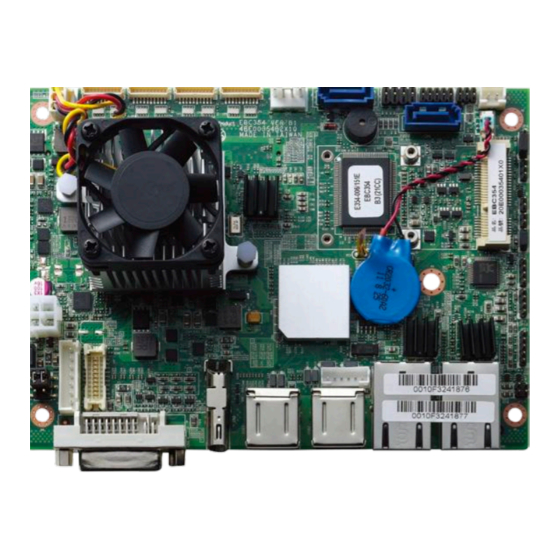
Page 18: Knowing Your Ebc 354
(under the fan/ heatsink) Reset Power AT/ATX Select Line-out Mic-in +12V DC Input Speaker out LVDS LVDS Backlight DVI-I HDMI USB1 USB2 LAN1 LAN2 USB 4/5 Copyright © 2012 NEXCOM International Co., Ltd. All rights reserved EBC 354 User Manual... -
Page 19: Chapter 2: Jumpers And Connectors
• Always disconnect the unit from the power outlet whenever you are recommended that you do not use needle-nosed pliers to disconnect working inside the case. Copyright © 2012 NEXCOM International Co., Ltd. All rights reserved EBC 354 User Manual... - Page 20 • Leave all components inside the static-proof packaging that they shipped with until they are ready for installation. • Use correct screws and do not over tighten screws. Copyright © 2012 NEXCOM International Co., Ltd. All rights reserved EBC 354 User Manual...
-
Page 21: Jumper Settings
(on) and open (off). Two-Pin Jumpers: Open (Left) and Short (Right) Three-Pin Jumpers: Pins 1 and 2 are Short Copyright © 2012 NEXCOM International Co., Ltd. All rights reserved EBC 354 User Manual... -
Page 22: Locations Of The Jumpers And Connectors
Chapter 2 : Jumpers and Connectors Locations of the Jumpers and Connectors The figure below shows the location of the jumpers and connectors. Copyright © 2012 NEXCOM International Co., Ltd. All rights reserved EBC 354 User Manual... -
Page 23: Jumpers
Connector location: JP8 Settings Settings 1-2 On Normal 1-2 On 2-3 On Clear BIOS 2-3 On 1-2 On: default 1-2 On: default Definition Definition I_PWRBT# I_RTCRST# AT_PWRBT# ATX_BOT Copyright © 2012 NEXCOM International Co., Ltd. All rights reserved EBC 354 User Manual... -
Page 24: Lvds Power Select
VCC_SEL PL_BKLTCTRL CCFLBKLTCTRL VCC5 P_BKLTCTRL PWM_DUTY 1-2 On: default 1-3 On: Analog signal output for dimming control. (default) 3-5 On: PWM signal output for dimming control. Copyright © 2012 NEXCOM International Co., Ltd. All rights reserved EBC 354 User Manual... -
Page 25: Connector Pin Definitions
CH_TX0_P HDMI_DATA0_N HDMI_CLK_P DVI_I_GND DDCCLK_VGA HDMI_CLK_N DDCDATA_VGA DVI_I_GND CH_CLK_P CH_CLK_N HDMI_CTRL_CLK HDMI_CTRL_DATA RED_VGA GREEN_VGA HDMI_VCC5 BLUE_VGA HSYNC_VGA HDMI_HPD_R Chassis_GND1 VGADET CRT_GND Chassis_GND1 Chassis_GND1 CHASIS_GND CHASIS_GND Chassis_GND1 Copyright © 2012 NEXCOM International Co., Ltd. All rights reserved EBC 354 User Manual... -
Page 26: Usb0/1 Ports
Connector location: USB2 Definition Definition Definition Definition P5V_USB_P01 USBCON_0N P5V_USB_P23 USBCON_2N USBCON_0P USBCON_2P P5V_USB_P01 USBCON_1N P5V_USB_P23 USBCON_3N USBCON_1P USBCON_3P USB1_MTH_GND USB1_MTH_GND USB2_MTH_GND USB2_MTH_GND USB1_MTH_GND USB1_MTH_GND USB2_MTH_GND USB2_MTH_GND Copyright © 2012 NEXCOM International Co., Ltd. All rights reserved EBC 354 User Manual... -
Page 27: Lan1 Port
LAN2_MDI1P LAN2_MDI2P LAN1TCT(LAN11V9) LAN1TCTG LAN2TCT(LAN21V9) LAN2TCTG LAN1_MDI2N LAN1_MDI1N LAN2_MDI2N LAN2_MDI1N LAN1_MDI3P LAN1_MDI3N LAN2_MDI3P LAN2_MDI3N LAN1_LEDACT# LAN1_ACTPW LAN2_LEDACT# LAN2_ACTPW LAN1_LINK LAN1_LINK100# LAN2_LINK LAN2_LINK100# LAN1_MTH_GND LAN1_MTH_GND LAN2_MTH_GND LAN2_MTH_GND Copyright © 2012 NEXCOM International Co., Ltd. All rights reserved EBC 354 User Manual... -
Page 28: Internal Connectors
Connector type: 1x10 10-pin header, 1.0mm pitch Connector location: CN3 Connector location: J3 Definition +12V CPUFANIN_R Definition Definition CPUFANOUT_R SP1_DCD SP1_RXD SP1_TXD SP1_DTR SP1_DSR SP1_RTS SP1_CTS SP1_RI Copyright © 2012 NEXCOM International Co., Ltd. All rights reserved EBC 354 User Manual... -
Page 29: Com2 Connector
Definition TXD- TXD+ RXD+ RXD- RTS- RTS+ CTS+ CTS- RS485 Pin Definition Definition Definition Definition TXD- TXD+ Reserve RXD- RXD+ Reserve Reserve Reserve Reserve Reserve Reserve Copyright © 2012 NEXCOM International Co., Ltd. All rights reserved EBC 354 User Manual... -
Page 30: Com4 Connector
Connector type: 1x4 4-pin Wafer, 2.54mm pitch Connector location: J1 Connector location: CN1 Definition +12V VCC5 Definition Definition SP4_DCD SP4_RXD SP4_TXD SP4_DTR SP4_DSR SP4_RTS SP4_CTS SP4_RI Copyright © 2012 NEXCOM International Co., Ltd. All rights reserved EBC 354 User Manual... -
Page 31: Sata1 Connector
Connector type: Standard Serial ATAII 7P (1.27mm, SATA-M-180) Connector type: Standard Serial ATAII 7P (1.27mm, SATA-M-180) Connector location: CN2 Connector location: CN4 Definition Definition SATA_TXP0_C SATA_TXP1_C SATA_TXN0_C SATA_TXN1_C SATA_RXN0_C SATA_RXN1_C SATA_RXP0_C SATA_RXP1_C Copyright © 2012 NEXCOM International Co., Ltd. All rights reserved EBC 354 User Manual... -
Page 32: Sata Dom Power Connector
Connector type: 1x2 JST, 2-pin header, 2.5mm pitch Connector type: 2x4 8-pin header, 2.54mm Connector location: J5 Connector location: JP3 Definition Definition Definition Definition VCC5 5V_KB 5V_KB KDAT_R MDAT_R KCLK_R MCLK_R KBMS_GND KBMS_GND Copyright © 2012 NEXCOM International Co., Ltd. All rights reserved EBC 354 User Manual... -
Page 33: Gpio Connector
Connector type: 2x3 6-pin header, 2.0mm pitch Connector location: JP2 Connector location: JP1 Definition Definition Definition Definition VCC5 UIM_PWR SIO_GPO24 SIO_GPI20 UIM_RESET UIM_VPP SIO_GPO25 SIO_GPI21 UIM_CLK UIM_DATA SIO_GPO26 SIO_GPI22 SIO_GPO27 SIO_GPI23 Copyright © 2012 NEXCOM International Co., Ltd. All rights reserved EBC 354 User Manual... -
Page 34: Battery Connector
Connector type: 1x2 JST, 2-pin header, 2.5mm pitch Connector type: 1x3 3-pin header 2.00mm-M-180 Connector location: J6 Connector location: JP5 Definition Definition Definition Definition BAT_C SMBCLK_MAIN SMBDATA_MAIN Copyright © 2012 NEXCOM International Co., Ltd. All rights reserved EBC 354 User Manual... -
Page 35: Reset Button Connector
Connector type: 1x2 2-pin header, 2.00mm pitch Connector type: 1x2 2-pin header, 2.00mm pitch Connector location: JP6 Connector location: JP7 Definition Definition Definition Definition I_SYSRST# ATX_BOT Copyright © 2012 NEXCOM International Co., Ltd. All rights reserved EBC 354 User Manual... -
Page 36: Line-Out Connector
Connector type: 1x4 4-pin header, 2.0mm pitch Connector type: 1x4 4-pin header, 2.0mm pitch Connector location: JP9 Connector location: JP10 Definition Definition Definition Definition LOUT_L2 AGND MIC_L3 AGND EXLINEOUT_JD LOUT_R2 MIC_JD LOUT_R3 Copyright © 2012 NEXCOM International Co., Ltd. All rights reserved EBC 354 User Manual... -
Page 37: Speaker-Out Connector
Connector type: 1x5 5-pin header, 2.0mm pitch Connector type: 2x2 4-pin header, 2.0mm pitch Connector location: JP11 Connector location: JP14 Definition Definition Definition Definition FRONT_L+ FRONT_L- PWRLEDP AGND FRONT_R+ HDDLEDP FRONT_R Copyright © 2012 NEXCOM International Co., Ltd. All rights reserved EBC 354 User Manual... -
Page 38: Usb4/5 Jst Connector
M_LVDSDDCCLK M_LVDSDDCDATA VCC_LCD LVDS_CH_TX0_P LVDS_CH_TX3_P LVDS_CH_TX0_N Definition Definition LVDS_CH_TX3_N VCC_LCD P5V_USB_P45 USBCON_4N LVDS_CH_TX1_P USBCON_4P USBCON_5N LVDS_CH _CLK_P LVDS_CH_TX1_N USBCON_5P LVDS_CH _CLK_N V_INV(+12V) LVDS_CH_TX2_P V_INV (+12V) LVDS_CH_TX2_N Copyright © 2012 NEXCOM International Co., Ltd. All rights reserved EBC 354 User Manual... -
Page 39: Lvds Backlight Connector
Connector type: 1x7 JST, 7-pin header, 2.5mm pitch Connector type: 2x2 Aux power connector Connector location: J8 Connector location: CON1 Definition Definition Definition Definition VCC5 V_INV(+12V) V_INV(+12V) BKLTCTRL +12V +12V M_BKLTEN_R Copyright © 2012 NEXCOM International Co., Ltd. All rights reserved EBC 354 User Manual... -
Page 40: Mini-Pcie Slot
Mini-PCIe Slot Connector location: CN5 Definition Definition I_WAKE# +3VSB_MINI1 SMB_CLK I_PETXN3_C SMB_DATA I_PETXP3_C MINICARD1CLKREQ# MINI1USBN MINI1USBP G_MINIPCIECLKN +3VSB_MINI1 G_MINIPCIECLKN +3VSB_MINI1 MINICARD1DIS# I_SLOTPLTRST# I_PERXN3 +3VSB_MINI1 +3VSB_MINI1 I_PERXP3 Copyright © 2012 NEXCOM International Co., Ltd. All rights reserved EBC 354 User Manual... -
Page 41: Block Diagram
Page 31 Page 34 HEAD PHONE Page 22 TPS6047A4RHBR SPEAKER Thermal Sensor *2 Page 22 Voltages *4 Page 22 Page 31 35 FAN *1 Page 35 Copyright © 2012 NEXCOM International Co., Ltd. All rights reserved EBC 354 User Manual... -
Page 42: Board Dimensions
Chapter 2 : Jumpers and Connectors Board Dimensions Copyright © 2012 NEXCOM International Co., Ltd. All rights reserved EBC 354 User Manual... -
Page 43: Chapter 3: Bios Setup
BIOS is updated in the future. use the computer. To check for the latest updates and revisions, visit the NEXCOM Web site When to Configure the BIOS at www.nexcom.com.tw. -
Page 44: Default Configuration
Use the up and TO ENTER SETUP BEFORE BOOT PRESS <CTRL-ALT-ESC> down arrow keys to scroll through all the available fields. Press the <Del> key to enter Setup: Copyright © 2012 NEXCOM International Co., Ltd. All rights reserved EBC 354 User Manual... - Page 45 When “” appears on the left of a particular field, it indicates that a submenu which contains additional options are available for that field. To display the submenu, move the highlight to that field and press <Enter>. Copyright © 2012 NEXCOM International Co., Ltd. All rights reserved EBC 354 User Manual...
-
Page 46: Bios Setup Utility
Monday to Sunday. Month displays the month, from January to December. Date displays the date, from 1 to 31. Year displays the year, from 1999 to 2099. Copyright © 2012 NEXCOM International Co., Ltd. All rights reserved EBC 354 User Manual... - Page 47 00 to 23. Minute displays minutes from 00 to 59. Second displays seconds from 00 to 59. Access Level Displays the access level of the current user in the BIOS. Copyright © 2012 NEXCOM International Co., Ltd. All rights reserved EBC 354 User Manual...
-
Page 48: Advanced
OS (Windows Server 2003 SP1, to LAN1 and LAN2. Windows XP SP2, SuSE Linux 9.2, RedHat Enterprise 3 Update 3). Copyright © 2012 NEXCOM International Co., Ltd. All rights reserved EBC 354 User Manual... - Page 49 Windows series operating systems. If you are using an operating system other than Windows, this problem may occur. To avoid this problem, enable this field to limit the return value to 3 or lesser than 3. Copyright © 2012 NEXCOM International Co., Ltd. All rights reserved EBC 354 User Manual...
- Page 50 Host Controller Interface). AHCI allows the storage driver to enable the advanced Serial ATA features which will increase storage performance. SATA Controller(s) Enables or disables SATA ports 0-3. Copyright © 2012 NEXCOM International Co., Ltd. All rights reserved EBC 354 User Manual...
- Page 51 Legacy USB Support] Enable Enables Legacy USB. Auto Disables support for Legacy when no USB devices are connected. Disable Keeps USB devices available only for EFI applications. Copyright © 2012 NEXCOM International Co., Ltd. All rights reserved EBC 354 User Manual...
- Page 52 Selects an optimal setting for the Super IO device. Onboard Serial Port Max Baud Rate Select this to change the max baud rate of the serial port. Copyright © 2012 NEXCOM International Co., Ltd. All rights reserved EBC 354 User Manual...
- Page 53 Select this to change the max baud rate of the serial port. Onboard Serial Port Max Baud Rate Select this to change the max baud rate of the serial port. Copyright © 2012 NEXCOM International Co., Ltd. All rights reserved EBC 354 User Manual...
- Page 54 Onboard Serial Port Max Baud Rate Select this to change the max baud rate of the serial port. Detects and displays the current CPU fan speed. Copyright © 2012 NEXCOM International Co., Ltd. All rights reserved EBC 354 User Manual...
- Page 55 Chapter 3: BIOS Setup CPU: Vcore Detects and displays the output voltages. Copyright © 2012 NEXCOM International Co., Ltd. All rights reserved EBC 354 User Manual...
-
Page 56: Chipset
Intel IGD Configuration Configures the options for Intel IGD function. Memory Information Detects and displays information on the memory installed in the system. Copyright © 2012 NEXCOM International Co., Ltd. All rights reserved EBC 354 User Manual... - Page 57 Enables or disables the Azalia HD audio. SMBus Controller Enables or disables the SMBus controller. High Precision Timer Enables or disables the high precision event timer. Copyright © 2012 NEXCOM International Co., Ltd. All rights reserved EBC 354 User Manual...
-
Page 58: Boot
Adjust the boot sequence of the system. Boot Option #1 is the first boot device that the system will boot from, next will be #2 and so forth. Copyright © 2012 NEXCOM International Co., Ltd. All rights reserved EBC 354 User Manual... -
Page 59: Security
To exit the Setup utility without saving the changes, select this field then press <Enter>. You may be prompted to confirm again before exiting. You can also press <ESC> to exit without saving the changes. Copyright © 2012 NEXCOM International Co., Ltd. All rights reserved EBC 354 User Manual... - Page 60 To use the current configurations as user default settings for the BIOS, select this field then press <Enter>. A dialog box will appear. Confirm by selecting Yes. Copyright © 2012 NEXCOM International Co., Ltd. All rights reserved EBC 354 User Manual...
-
Page 61: Appendix A: Watchdog Timer
Users can set time-out value. al, 07h 2eh, al Step4: See ExitSetup procedure al, 07h ;Select logical device for Watch Dog. #Exit Setup Environment 2fh, al (ref) SetupWDT ENDP Copyright © 2012 NEXCOM International Co., Ltd. All rights reserved EBC 354 User Manual... - Page 62 73h ;WDT Time-out register. 2eh, al al, 03h ;Here!! Set count 3. 2fh, al TimeCountWDT ENDP ExitSetup PROC al, 02h 2eh, al al, 02h 2fh, al ExitSetup ENDP Copyright © 2012 NEXCOM International Co., Ltd. All rights reserved EBC 354 User Manual...
-
Page 63: Appendix B: Gpi/O Programming Guide
GPO25 GPI21 Bit4 : GPO24 GPO26 GPI22 Bit5 : GPO25 GPO27 GPI23 Bit6 : GPO26 Bit7 : GPO27 1. Read/Write GPIO data by I/O port A04h Copyright © 2012 NEXCOM International Co., Ltd. All rights reserved EBC 354 User Manual...
Need help?
Do you have a question about the EBC 354 and is the answer not in the manual?
Questions and answers