
Subscribe to Our Youtube Channel
Related Manuals for Nexcom PEAK 760 Series


Summary of Contents for Nexcom PEAK 760 Series
- Page 1 Single Board Computer PEAK 760 Series User’s Manual 01-17-2005 Build 02-09-2006 Update Prepared by Zack...
-
Page 2: Preface
Any implied warranties of merchantability of fitness for any particular purpose is also disclaimed. Acknowledgements The PEAK 760 series is a trademark of NEXCOM international CO., LTD. All other product names mentioned herein are registered trademarks of their respective owners. Regulatory Compliance Statements This section provides the FCC compliance statement for Class A devices and describes how to keep the system CE compliant. -
Page 3: Ce Certification
correct the interference (take adequate measures) at their own expense. CE Certification The product(s) described in this manual complies with all applicable European Union (CE) directives if it has a CE marking. For computer systems to remain CE compliant, only CE-compliant parts may be used. Maintaining CE compliance also requires proper cable and cabling techniques. -
Page 4: Table Of Contents
Table of Content Preface ……………...……………..……………………………………….………….…………………..1 Copyright ………………..……………………………………….……………………………………..1 Disclaimer ………………………..………………………………..…………………………………….. 1 Acknowledgements ……………………………………………..………………………………..…… 1 Regulatory Compliance Statements ……………………..…………………………………………1 Federal Communications Commission (FCC) For Class A Device ……………..……….…1 CE Certification ………………………………………………………………………………………...2 Safety Information ……………………………………………………………………………………..2 Table of Content ……………………………………………………………………………………. Chapter 1 General Information 1.1 Main Feature…………………………………………………….…………………………………….. - Page 5 4.8 Advanced BIOS Features…………………………………………………………………………. 46 4.9 Integrated Peripherals………………………………………………………………...………… 48 4.10 Power Management Setup…………………………………………………………………….. 50 4.11 PnP/PCI Configurations…………………………………………………………………………. 52 4.12 PC Health Status………………………………………………………………………………… 53 4.13 Load Fail-Safe Defaults…………………………………………………………………………. 53 4.14 Load Optimized Defaults………………………………………………………………………... 53 4.15 Set Password…………………………………………………………………………………….. 54 4.16 Save & Exit Setup……………………………………………………………………………….. 54 4.17 Exit Without Saving……………………………………………………………………………...
- Page 6 PEAK 760 User’s Manual...
-
Page 7: Chapter 1 General Information
Chapter 1 General Information PEAK 760 User’s Manual Chapter 1... -
Page 8: Main Feature
1.1 Main Feature Support socket LGA775 Intel® Pentium 4 Hyper-Threading Technology with 533/800 MHz FSB, speed up to 3.8GHz Intel® 915GV and ICH-6 chipsets • 240-pin DIMM x 4, support dual channel DDR2 400/533 up to 3.2 GB • Intel® PC82573L PCI Express Gigabit Ethernet Controller x 2 supporting two GbE LAN ports •... - Page 9 System Architecture - PICMG Socket LGA775 Full-Sized SBC - Single socket LGA 775 CPU Support - Support Intel® Pentium® 4 processor with 533/800 MHz FSB, speed up to 3.8 GHz - Support Intel® Hyper-Threading technology Memory - 4 x 240-pin DIMM - *Dual channel DDR2 400/533 MHz, up to 3.2 GHz - Plug &...
- Page 10 - 2-pin header for SMBus 2.0 - 4-pin FAN Jst connector x 1 (For CPU); 3-pin FAN connector x 2 - 5-pin connector x 1 for Chassis or Backplane Front Keyboard - Pin Header Key Lock/Power LED/HDD LED - VGA DB-15 connector x 1 I/O on Bracket - RJ45 Gigabit Ethernet LAN port x 2 - Mini-DIN for Keyboard/mouse x 1...
-
Page 11: Power Consumption Measurement
Ordering Information PEAK 760VL (LF) Full-sized LGA775 socket support Intel Pentium-4/ Celeron-D CPU board with PCI Express Gigabit Ethernet LAN port x 1 PEAK 760VL2 (LF) Full-sized LGA775 socket support Intel Pentium-4/ Celeron-D CPU board with PCI Express Gigabit Ethernet LAN port x 2 1.3 Power Consumption Measurement Required watts and currents for Power Supply Power Type... -
Page 12: Board Layout
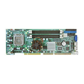
1.4 Board Layout Figure 1.2: Overview of PEAK 760 PEAK 760 User’s Manual Chapter 1... -
Page 13: Board Dimensions
1.5 Board Dimensions Figure 1.3: Mechanical Drawing of the PEAK-760 PEAK 760 User’s Manual Chapter 1... - Page 14 PEAK 760 User’s Manual Chapter 1...
- Page 15 Chapter 2 Jumper Setting PEAK 760 User’s Manual...
-
Page 16: Before You Begin
This chapter of the User’s Manual describes how to set jumpers. Note: The procedures that follow are generic for all PEAK 760 series. 2.1 Before You Begin Ensure you have a stable, clean working environment. Dust and dirt can get into components and cause a malfunction. -
Page 17: Setting Jumpers
2.3 Setting Jumpers A jumper is the simplest kind of electric switch. It consists of two metal pins and a cap. When setting the jumpers, ensure that the jumper caps are placed on the correct pins. When the jumper cap is placed on both pins, the jumper is SHORT. -
Page 18: Location Of Jumpers
2.4 Location of Jumpers Figure 2-1: Jumper Location 2.5 Function of Jumper Function RTC Clear CF Card Master/Slave Select Remark: J13 (for CF socket) has been removed as an option PEAK 760 User’s Manual... -
Page 19: Connector And Pin Definition
2.6 Connector and Pin Definition (1) AUX +12V Power Connector (J1) A. Connector size: ATX POWER CONN 2x2 B. Connector location C. Connector pin definition J1: AUX +12V Power Connector Definition Definition +12V +12V (2) SATA3/SATA 2/SATA1/SATA0 connector (J2)(J4)(J6)(J9) A. Connector size: 7 Pin, 1.27mm, 180°, SATA Connector B. - Page 20 (3) PIO Connector (J3) A. Connector size: 2 X 13 = 26 Pin, 2.0 mm, 180° ,BOX Header B. Connector location C. Connector pin definition J3: PIO Definition Definition Line Print Strobe Auto Feed# Parallel Data 0 Error# Parallel Data 1 Initialize# Parallel Data 2 Select Input#...
- Page 21 (5) CPU FAN Connector (J7) A. Connector size: 1 X 4 = 4 Pin, 2.54mm, 180°, FAN Connector B. Connector location C. Connector pin definition J7 : CPU FAN Definition Definition Sense +12V (6) SYSTEM FAN1/FAN2 Connector (J10)/(J12) A. Connector size: 1 X 3 = 3 Pin, 2.54mm, 180°, FAN Connector B.
- Page 22 (7) FLOPPY Connector (J11) A. Connector size: 2 x 17 = 34 pins, 2.54 mm, 180° ,BOX Header B. Connector location C. Connector pin definition J11: Floppy Definition Definition DIR# DENSEL# STEP# Write Data# WGATE# INDEX# TK00# MOTEA# WPT# DRVB# Read Data# DRVA# SIDE1#...
- Page 23 (9) External Keyboard Connector (J15) A. Connector size: 1 X 5 = 5 Pin, 2.54mm, 180°, JST Connector B. Connector location C. Connector pin definition J15: External Keyboard Definition Definition Keyboard Clock Keyboard Data (10) ATX Connector (J20) A. Connector size: 1 X 3 = 3 Pin, 2.54mm, 180°, JST Connector B.
- Page 24 (11) IDE Connector Primary IDE (J22) A. Connector size: 2 x 20 = 40pins, 2.54mm, 180°,BOX Header B. Connector location C. Connector pin definition J22: Primary IDE Definition Definition Reset# DMA REQ Data 7 IOW# Data 8 Data 6 IOR# Data 9 Data 5 IOCHRDY...
- Page 25 (12) Compact Flash Connector (J25) A. Connector size: Compact Flash Socket 50 Pin Connector B. Connector location C. Connector pin definition J25: CF Card Definition Definition Data 3 Data 11 Data 4 Data 12 Data 5 Data 13 Data 6 Data 14 Data 7 Data 15...
- Page 26 Data 2 Data 9 Data 10 (13) GPIO (J34) A. Connector size: 2X4 = 8 PIN, 2.54mm, 180°, PIN Header B. Connector location C. Connector pin definition J34: GPIO Definition Definition GP25_D_IN1 (PIN25) GP22_D_OUT2 (PIN22) GP20_D_OUT0 (PIN20) GP26_D_IN2 (PIN26) GP24_D_IN0 (PIN24) GP23_D_OUT3 (PIN23) GP21_D_OUT1 (PIN21) GP27_D_IN3 (PIN27)
- Page 27 (15) 82573L LAN1 (JP6) / LAN2 (JP1) LINK 100LED A. Connector size: 1X2 = 2 PIN, 2.54mm, 180° , PIN Header B. Connector location C . Connector pin definition JP6/JP1: LAN1/LAN2 LINK 100LED Definition Definition Speed1000# Speed100# (16) 82573L LAN1 (JP8) /LAN2 (JP2) LINK 1000LED A.
- Page 28 (18) IR (JP10) A. Connector size: 1X5 = 5 PIN, 2.54mm, 180°, PIN Header B. Connector location C. Connector pin definition JP10: IR Definition Definition CIRRX IRTX IRRX (19) Keyboard Lock (JP11) A. Connector size: 1X5 = 5 PIN, 2.54mm, 180°, PIN Header B.
-
Page 29: Power Led
(20) IDE LED/POWER LED/POWER ON/RESET/BUZZER/SMBUS/ System Thermal (JP19) A. Connector size: 2X8 = 16 PIN, 2.54mm, 180°, PIN Header B. Connector location C. Connector pin definition JP19: IDE LED/POWER LED/POWER ON/RESET/BUZZER/SMBUS/System Thermal Definition Definition Speaker SMB_ Data IDE_LED SMB_ Clock Power ON Reset :PIN1... - Page 30 (22) Key board + mouse Connector (CON4) A. Connector size: MINI DIN 6 Pin Connector B. Connector location C .Connector pin definition CON4: Key board + mouse Connector Definition Definition Keyboard Data +5VSB Mouse Data Keyboard Clock Mouse Clock (23) 82573L LAN2 Connector/82573L LAN1 Connector (CON5)(CON6) A.
- Page 31 (24) VGA Connector (CON7) A. Connector size: VGA DSUB 15 Pin Connector B. Connector location C. Connector pin definition CON7: VGA connector Definition Definition Green Blue DDC Data HSYNC VSYNC DDC Clock (25) RTC Clear (JP9) A. Connector size: 1X3 = 3 PIN, 2.54mm, 180° , PIN Header B.
- Page 32 (26) CF Card Master/Slave Select (J13) A. Connector size: 1 X 3 = 3 PIN, 2.54mm, 180° , PIN Header B. Connector location C. Connector pin definition CF Card Master/Slave Select Slave Master *2-3 * = DEFAULT SET Remark: J13 (for CF socket) has been removed as an option 3 PCI Device interrupt and BUS Assignments Chipset Configuration...
-
Page 33: Chapter 3 Expansion
Chapter 3 Expansion PEAK 760 User’s Manual... -
Page 34: System Memory
3.1 System Memory PEAK 760 incorporates Intel 915GV chipset supports dual channel non-ECC un-buffered DDR2 400/533 MHz memory up to 4GB. Four 240-pins DIMM sockets support up to a maximum 4GB DIMM. Followings are the recommended memory modules. Size (MB) Technology Type Vendor Remark... -
Page 35: Installing Dimm
3.2 Installing DIMM To install DIMM 1. Make sure the two handles of the DIMM sockets are in the “open” position, i.e. the handles stay outward. Figure3-1: How to Install DIMM (1) 2. Slowly slide the DIMM modules along the plastic guides in the both ends of the socket. Figure 3-2: How to Install DIMM (2) PEAK 760 User’s Manual... - Page 36 3. Then press the DIMM module down right into the socket, until a click is heard. That means the two handles automatically locked the memory modules into the right position of the DIMM socket. Figure 3-3: How to Install DIMM (3) 4.
-
Page 37: Installing Compact Flash
3.3 Installing Compact Flash 1. To install a Compact Flash memory card into PAEK 760, align the notches on the card with the Compact Flash socket in the PEAK 760. Then firmly insert the card into the socket until it is completely seated. -
Page 38: Installing Intel Pentium-M Cpu And Fan Heatsink
3.4 Installing socket LGA775 Intel Pentium-4 CPU, Heat Sink, and Fan Since the socket 775 is comprised of sensitive arrays of pins, improper or careless installation may cause permanent harm to the CPU. In some cases users may accidentally damage the socket simply by adjusting the position of the CPU. - Page 39 Step 3: a. Verify that the CPU if properly mated to the orientation keys. b. Close the upper plate, place the load lever back to the original position. Step 4: a. Place the Heat Sink with Fan Set onto the four holes around the CPU socket making sure that the four screws are aligned with the holes on the PEAK 760.
-
Page 40: Chapter 4 Award Bios Setup
Chapter 4 Award BIOS Setup PEAK 760 User’s Manual Appendix A... -
Page 41: About The Bios
BIOS modification in the future. User can download any major updated items or reversion from NEXCOM web site http://www.nexcom.com.tw. If any unclear message occurs, please contact NEXCOM customer service representative for help or log onto http://www.nexcom.com.tw/contact/contact.htm. -
Page 42: Entering Setup
4.3 Entering Setup When the system is powered on, the BIOS will enter the Power-On Self Test (POST) routines. These routines perform various diagnostic checks; if an error is encountered, the error will be reported in one of two different ways: If the error occurs before the display device is initialized, a series of beeps will be transmitted. -
Page 43: Getting Help
Standard CMOS Features Use this menu for basic system configuration. Advanced BIOS Features Use this menu to set the Advanced Features available on the system. Integrated Peripherals Use this menu to specify your settings for integrated peripherals. Power Management Setup Use this menu to specify your settings for power management. -
Page 44: Control Keys
4.6 Control Keys The table below lists the keys that help you navigate the setup program. Up arrow Move to previous item Down arrow Move to next item Left arrow Move to the item to the left Right arrow Move to the item to the right Esc key Main Menu: Quit without saving changes to CMOS Status/Option Page Setup Menus: Exit current page and... -
Page 45: Standard Cmos Features
4.7 Standard CMOS Features Selecting Standard CMOS Features on the main program screen displays the following menu: Figure 4-2: BIOS – Standard CMOS Features The Standard CMOS Setup utility is used to configure the following features: Date (mm:dd:yy) The BIOS determines the day of the week from the other data information. This field is for information only. - Page 46 Precomp Write pre-compensation cylinder Landing Zone Landing zone Sector Number of sector Refer to your drive’s documentation or look on the drive if you need to obtain this information. If no device is installed, change the value to None. Drive A Select this field to the type of floppy disk drive installed in your system.
-
Page 47: Advanced Bios Features
4.8 Advanced BIOS Features Selecting Advanced BIOS Feature on the main program screen displays this menu, which allows you to define advanced information about your system. You can make modifications to most of these items to improve your system performance or set up system features according to your preference, without causing fatal errors to your system. - Page 48 Note: This function is available only for DOS and other operating systems that do not trap INT13. For complete protection against viruses, install virus software in your operating system and update the virus definitions regularly. Many disk diagnostic programs that access the boot sector table can trigger the virus warning message.
-
Page 49: Integrated Peripherals
4.9 Integrated Peripherals Figure 4-4: BIOS – Integrated Peripherals OnChip IDE Device Select this item to setup the IDE device features. When you select this item, the following menu shows: USB Controller Select Enabled if your system contains a Universal Serial Bus controller. USB 2.0 Controller Select Enabled if your system contains a Universal Serial Bus 2.0 controller and you have USB 2.0 peripherals. - Page 50 PCI graphics card. Onboard LAN 1/2 H/W Active Enables and disables the onboard LAN modules. Onboard FDC Controller Select Enabled if your system has a floppy disk controller (FDC) installed on the system board and you wish to use it. If you install an add-in FDC or the system has no floppy drive, select Disabled to this field. Onboard Serial Ports (1, 2) This feature allows you to manually select the I/O address and IRQ for the first and second serial ports.
-
Page 51: Power Management Setup
4.10 Power Management Setup This option lets you control system power management. The system has various power-saving modes including powering down the hard disk, turning off the video, and software power down that allows the system to be automatically resumed by certain events. The power-saving modes can be controlled by timeouts. - Page 52 Video Off Method This determines the manner in which the monitor is blanked. There are three choices: 1. V/H SYNC+Blank: This selection will cause the system to turn off the vertical and horizontal synchronization port and write blanks to the video buffer. 2.
-
Page 53: Pnp/Pci Configurations
4.11 PnP/PCI Configurations This section describes configuring the PCI bus system. Peripheral Component Interface is a system, which allows I/O devices to operate at speeds nearing the speed the CPU itself, uses when communicating with its own special components. This section covers some very technical items and it is strongly recommended that only experienced users should make any changes to the default settings. -
Page 54: Pc Health Status
4.12 PC Health Status When main boards support hardware monitoring, this item lets you monitor the parameters for critical voltages, critical temperatures, and fan speeds. These are the read only items. After you have read the PC Health Status, press the <ESC> key to go back to the main program screen. Figure 4-7: PC Health Status 4.13 Load Fail-Safe Defaults This option opens a dialog box that lets you install fail-safe defaults for all appropriate items in the whole... -
Page 55: Set Password
4.15 Set Password The User Password utility sets the password. The main board is shipped with the password disabled. If you want to change the password, you must first enter the current password, then at the prompt enter your new password. The password is case sensitive. You can use up to eight alphanumeric characters. Press <Enter>... -
Page 56: Chapter 5 Driver Installation
Chapter 5 Driver Installation PEAK 760 User’s Manual Appendix A... -
Page 57: Installation Cd
3. Install the graphic driver and utilities. 4. Install the LAN drivers. It is recommended that the chipset, graphic, and LAN drivers provided on the Nexcom CD be used to ensure compatibility. Note: You should install the Intel chipset patch before installing other drivers. -
Page 58: Installing Intel Chipset
5.3 Installing Intel Chipset The chipset patch updates the chipset and enables user to adjust the advanced chipset components. Step 5.3.1 Select the Chipset folder and double-click to open it Step 5.3.2 Click OK PEAK 760 User’s Manual Appendix A... - Page 59 Step 5.3.3 Click Next to continue installation Step 5.3.4 Read the License Agreement. If you accept it, click Yes to continue. PEAK 760 User’s Manual Appendix A...
- Page 60 Step 5.3.5 Read the Readme file and click Next button to continue the installation process. Step 5.3.6 The program updates your computer driver files, and you are prompted to restart your computer. Click Yes, I want to restart my computer now and then click Finish button to reboot. PEAK 760 User’s Manual Appendix A...
-
Page 61: Installing Vga
5.4 Installing VGA Step 5.4.1 Following the steps as shown below Step 5.4.2 Select your Operation System PEAK 760 User’s Manual Appendix A... - Page 62 Step 5.4.3 Run this program from its current location then click OK Step 5.4.4 Click Yes to continue installation. PEAK 760 User’s Manual Appendix A...
- Page 63 Step 5.4.5 Click Next to continue installation. Step 5.4.6 Click Next to continue installation. PEAK 760 User’s Manual Appendix A...
- Page 64 Step 5.4.7 Read the License Agreement. If you agree it, click Yes to continue. Step 5.4.8 The complete installation screen appears. Select Yes, I want to restart my computer now, and click Finish to reboot your computer. PEAK 760 User’s Manual Appendix A...
-
Page 65: Installing The Lan
5.5 Installing the LAN Step 5.5.1 Double click the Control Panel icon to open it. Step 5.5.2 Double click the System icon. PEAK 760 User’s Manual Appendix A... - Page 66 Step 5.5.3 In the system properties dialog, click to open the Hardware page and then click Device Manager button on the page. Step 5.5.4 Click on the Ethernet Controller PEAK 760 User’s Manual Appendix A...
- Page 67 Step 5.5.5 Click right button on the Mouse, then click Properties Step 5.5.6 Then click Update driver PEAK 760 User’s Manual Appendix A...
- Page 68 Step 5.5.7 Click Next Step 5.5.8 Click Next PEAK 760 User’s Manual Appendix A...
- Page 69 Step 5.5.9 Choose Network Adapters and click Next Step 5.5.10 Choose Have Disk PEAK 760 User’s Manual Appendix A...
- Page 70 Step 5.5.11 Click Browse Step 5.5.12 Choose LAN\Windows 2KXP\PRO1000\WS03XP2K as shown below PEAK 760 User’s Manual Appendix A...
- Page 71 Step 5.5.13 Choose e1000325.inf to open the file then click OK Step 5.5.14 Click OK PEAK 760 User’s Manual Appendix A...
- Page 72 Step 5.5.15 Choose Intel® PRO/1000 PL Network Connection, then click Next Step 5.5.16 To continue the installation, click Yes PEAK 760 User’s Manual Appendix A...
- Page 73 Step 5.5.17 To continue the installation, click Next Step 5.5.18 To close this wizard, click Finish. PEAK 760 User’s Manual Appendix A...
-
Page 74: Appendix A Watchdog Timer
Appendix A Watchdog Timer PEAK 760 User’s Manual Appendix A... -
Page 75: Watchdog Timer
The PEAK 760 features a watchdog timer that reset the CPU or generates an interrupt if the processor stops operating for any reason. This feature ensures system reliability in industrial standalone or unmanned environments. Panel Button De-bounce Base Address LSB Register (Index=65h, Default=00h) Description Read/write, mapped as Base Address [7:0] Panel Button De-bounce Interrupt Level Select Register (Index=70h, Default=00h) - Page 76 Watch Dog Timer Time-Out Value Register (Index=73h, Default=00h) Description WDT time-out value 7-0 Sample Code: ;Enter config mode out 2E, 87h out 2E, 01h out 2E, 55h out 2E, 55h ;Set LDN=7 out 2E, 07h out 2F, 07h ;Set WDT enable, second mode out 2E, 72h out 2F, 0C0h ;Set value=3...
-
Page 77: Appendix B Gpi/O
Appendix B Appendix B GPI/O Programming GPI/O PEAK 760 User’s Manual Appendix B... -
Page 78: Gpio User Guide
GPIO User Guide Digital I/O UESD Port 801 GP27_D_IN3 GP26_D_IN2 GP25_D_IN1 GP24_D_IN0 GP23_D_out3 GP22_D_out2 GP21_D_out1 GP20-_D_out0 Iput Output GP20_D_out1 GP24_D_IN0 GP21_D_out2 GP25_D_IN1 GP22_D_out2 GP26_D_IN2 GP23_D_out3 GP27_D_IN3 Prepared by Zack at Taipei PEAK 760 User’s Manual Appendix B...
Need help?
Do you have a question about the PEAK 760 Series and is the answer not in the manual?
Questions and answers