Table of Contents
Advertisement
Quick Links
Preface
Copyright
This publication, including all photographs, illustrations and software, is protected under international copy-
right laws, with all rights reserved. No part of this manual maybe reproduced, copied, translated or transmit-
ted in any form or by any means without the prior written consent from NEXCOM International Co., Ltd.
Version 1.0
Copyright 2003
Disclaimer
The information in this document is subject to change without prior notice and does not represent commit-
ment from NEXCOM International Co., LTD. However, users may update their knowledge of any product in
use by constantly checking its manual posted on our website: http://www.nexcom.com. NEXCOM shall not
be liable for direct, indirect, special, incidental, or consequential damages arising out of the use of any
product, nor for any infringements upon the rights of third parties, which may result from such use. Any
implied warranties of merchantability of fitness for any particular purpose is also disclaimed.
Acknowledgements
EBC575 is a trademark of NEXCOM international CO., LTD. All other product names mentioned herein are
registered trademarks of their respective owners.
Regulatory Compliance Statements
This section provides the FCC compliance statement for Class A devices and describes how to keep the
system CE compliant.
FEDERAL COMMUNICATIONS COMMISSION (FCC) FOR CLASS A DEVICES
This equipment has been tested and verified to comply with the limits for a Class A digital device, pursuant to
Part 15 of FCC Rules. These limits are designed to provide reasonable protection against harmful interfer-
ence when the equipment is operated in a commercial environment. This equipment generates, uses, and
can radiate radio frequency energy and, if not installed and used in accordance with the instructions, may
cause harmful interference to radio communications. Operation of this equipment in a residential area (domestic
environment) is likely to cause harmful interference, in which case the user will be required to correct the
interference (take adequate measures) at their own expense.
CE CERTIFICATION
The product(s) described in this manual complies with all applicable European Union (CE) directives if it has
a CE marking. For computer systems to remain CE compliant, only CE-compliant parts may be used. Main-
taining CE compliance also requires proper cable and cabling techniques.
1
Advertisement
Table of Contents

Subscribe to Our Youtube Channel
Related Manuals for Nexcom EBC575 Series


Summary of Contents for Nexcom EBC575 Series
- Page 1 This publication, including all photographs, illustrations and software, is protected under international copy- right laws, with all rights reserved. No part of this manual maybe reproduced, copied, translated or transmit- ted in any form or by any means without the prior written consent from NEXCOM International Co., Ltd. Version 1.0...
- Page 2 WARNINGS Read and adhere to all warnings, cautions, and notices in this guide and the documentation supplied with the chassis, power supply, and accessory modules. If the instructions for the chassis and power supply are inconsistent with these instructions or the instructions for accessory modules, contact the supplier to find out how you can ensure that your computer meets safety and regulatory CAUTION Electrostatic discharge (ESD) can damage EBC components.
-
Page 3: Table Of Contents
Table of Contents Preface ..........................1 Chapter ..........................5 1.1 Features ...............................6 1.2 Specification ............................6 1.3 Checklist ..............................8 1.4 Board Layout ............................9 1.4.1 Front Layout ............................9 1.4.2 Rear Layout ...........................10 1.5 Board Dimensions ..........................11 Chapter 2 Jumper Setting ...................12 2.1 Before You Begin ..........................13 2.2 Precautions ............................13 2.3 Setting Jumpers ...... - Page 4 4.13 PC Health Status ..........................50 4.14 Load Fail-Safe Defaults ........................51 4.15 Load Optimized Defaults ........................51 4.16 Set Supervisor/User Password ......................52 4.17 Save & Exit Setup ..........................52 4.18 Exit Without Saving ..........................52 Chapter 5 Driver Installation ..................53 5.1 Installation CD ............................54 5.2 Installing Drivers for EBC575 .......................55 5.3 Installing Intel Chipset ..........................55 5.4 Installing the On-board VGA ........................57...
- Page 5 Chapter 1 General Information...
-
Page 6: Features
1.1 Features EBC575 Series is a member of NEXCOM’s P4-based Industrial Embedded Main Board Computer family. The features of this series are as follows: ® ® ® ® ® ® Intel Pentium 4 processor, Intel Celeron processor, or Intel Pentium -M processor, up to 3.06... - Page 7 On-board VGA ® Intel 82845GV chipset integrated with graphics controller Hardware motion compensation assist for software MPEG/DVD decode 64MB VGA share memory AGP 4X interface (1.5V) Fully PC98 and PC99 compliant On-board LVDS transmitters I/O ports VGA: 15-pin CRT connector x 1 / 2.0mm box header 8 x 2 CRT connector / RHS FD 14-pin connector for LVDS panel output LAN: RJ45 with LED connector x 3 USB port x 2, JST 2.0mm 6 pin Connector x 1...
-
Page 8: Checklist
Watchdog Timer Watchdog timeout can be programmable by software from 1 ~ 128 seconds Dimensions 203mm (L) x 146mm (W) Power Requirements +5V / +12V / +3.3V / +3.3VSB / 5VSB Note: Make sure that your ATX 12V power supply can provide at least 8 mA on the 12V lead and at least 1 mA on the +5 volt standby lead (+5VSB). -
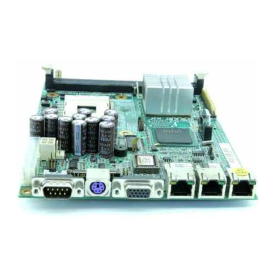
Page 9: Board Layout
1.4 Board Layout 1.4.1 Front Layout Figure 1-1: EBC575 Front Layout EBC575 User’s Manual Chapter 1... -
Page 10: Rear Layout
1.4.2 Rear Layout Compact Flash Connector Figure 1-2: EBC575 Rear Layout EBC575 User’s Manual Chapter 1... -
Page 11: Board Dimensions
1.5 Board Dimensions Physical Dimensions: 203mm (L) x 146mm (W) This concludes Chapter 1. The next chapter covers setting up the EBC575. EBC575 User’s Manual Chapter 1... -
Page 12: Chapter 2 Jumper Setting
Chapter 2 Jumper Setting... -
Page 13: Before You Begin
This chapter of the User’s Manual describes how to set jumpers. 2.1 Before You Begin Ensure you have a stable, clean working environment. Dust and dirt can get into components and cause a malfunction. Use containers to keep small components separated. Adequate lighting and proper tools can prevent you from accidentally damaging the internal components. -
Page 14: Setting Jumpers
2.3 Setting Jumpers A jumper is the simplest kind of electric switch. It consists of two metal pins and a cap. When setting the jumpers, ensure that the jumper caps are placed on the correct pins. When the jumper cap is placed on both pins, the jumper is SHORT. -
Page 15: Functions Of Jumpers
2.4 Functions of Jumpers You can use jumpers to set configuration options. The table below defines function of each jumper: t l o t o l i t c t n i Table 2-2: Function of Jumpers EBC575 User’s Manual Chapter 2... -
Page 16: Locating Jumpers And Switches
2.5 Locating Jumpers and Switches This and the following pages show the location of the main board jumpers and switches: Figure 2-1: EBC575 Board Main Jumpers and Switchs EBC575 User’s Manual Chapter 2... -
Page 17: Panel Power Select (J1)
2.6 Panel Power Select (J1) * Default 2.7 CPU Type Select (J25) * Default 2.8 CMOS clear (JP1) * Default Note: Clear CMOS procedure: 1. Turn off the system power 2. Short pin 2 and pin 3 on Jumper JP1. Wait 1~2 seconds. 3. - Page 18 J1: LVDS Panel J2: LVDS Panel EBC575 User’s Manual Chapter 2...
-
Page 19: Power Led (Jp3)
2.10 Power LED (JP3) 2.11 CF Card Master/Slave Select (JP4) 2.12 Power Connector (JP5) For detail jumper setting information, please refer to Appendix A. This ends Chapter 2. The next chapter covers EBC575 expending capabilities. EBC575 User’s Manual Chapter 2... -
Page 20: Chapter 3 Capability Expanding
Chapter 3 Capability Expanding... -
Page 21: System Memory
3.1 System Memory Your system memory is provided by DIMM’s (Dual In-Line Memory Modules) on the CPU board. The board contains two memory banks: Bank 0 and 1, corresponds to connector DIMM1, DIMM2. The table below shows possible DIMM Configurations for the memory banks. Please notice that the EBC575 support Double Data Rate Ram (DDR266). -
Page 22: Installing Dimm
3.2 Installing DIMM To install DIMM 1. Make sure the two handles of the DIMM sockets are in the “open” position, i.e. the handles stay outward. Figure 3-1: How to Install DIMM (1) 2. Slowly slide the DIMM modules along the plastic guides in the both ends of the socket. Figure 3-2: How to Install DIMM (2) EBC575 User’s Manual Chapter 3... - Page 23 3. Then press the DIMM module down right into the socket, until a click is heard. That means the two handles automatically locked the memory modules into the right position of the DIMM socket. Figure 3-3: How to Install DIMM (3) 4.
-
Page 24: Installing Compact Flash
3.3 Installing Compact Flash 1. To install a Compact Flash memory card into EBC575, reverse the main board. Align the notches on the Compact Flash memory card with the Compact Flash socket in the EBC575. Firmly insert the card into the socket until it is completely seated. -
Page 25: Change Cpu
3.4 Change CPU To change the CPU: 1. Pull the handling bar of the socket upward to the other end to loosen the socket’s openings. Carefully lift the existing CPU up to remove it from the socket. 2. Place the new CPU on the middle of the socket, orienting its beveled corner to line up with the socket’s beveled corner. -
Page 26: Installing The Fan Heatsink
3.5 Installing the Fan Heatsink Use the following instructions for installing the fan heatsink: 1. The heatsink has a thermal interface material attached to the bottom, shown in Figure 3-10. Do not damage the thermal interface material while installing. 2. Align the fan heatsink and slip assembly (A in Figure 3-9) with the retention mechanism (the fan heatsink is symmetrical) and place it on the processor (as shown in Figure 3-10). - Page 27 Figure 3-9: Installing the Fan Heatsink (1) Fan Heatsink and Clip Assembly Terminology Figure 3-11: Installing the Fan Heatsink (3) Figure 3-10: Installing the Fan Heatsink (2) Push Down Clip Frame Corners to Align Fan Heatsink and Clip Assembly Secure the Retention Mechanism Hooks EBC575 User’s Manual Chapter 3...
- Page 28 Figure 3-12b: Installing the Fan Heatsink (5) Figure 3-12a: Installing the Fan Heatsink (4) Close Clip Lever (1). While Holding Close Clip Levers. One at a Time the Topside of Fan Heatsink (A) Figure 3-12c: Installing the Fan Heatsink (6) Figure 3-13: Installing the Fan Heatsink (7) Close Clip Lever (2), while Holding Connect Fan Cable to the Main board...
-
Page 29: Chapter 4 Award Bios Setup
Chapter 4 Award BIOS Setup... -
Page 30: About The Bios
BIOS modification in the future. User can download any major updated items or reversion from NEXCOM web site http://www.nexcom.com.tw. If any unclear message occurs, please contact NEXCOM customer service representative for help or log onto http://www.nexcom.com.tw/contact/contact.htm. -
Page 31: Entering Setup
4.3 Entering Setup When the system is powered on, the BIOS will enter the Power-On Self Test (POST) routines. These rou- tines perform various diagnostic checks; if an error is encountered, the error will be reported in one of two different ways: If the error occurs before the display device is initialized, a series of beeps will be transmitted. -
Page 32: Getting Help
Advanced Chipset Features Use this menu to change the values in the chipset registers and optimize the system’s performance. Integrated Peripherals Use this menu to specify your settings for integrated peripherals. Power Management Setup Use this menu to specify your settings for power management. PnP/PCI Configurations This entry appears if your system supports Plug and Play and PCI Configuration. -
Page 33: Control Keys
4.6 Control Keys The table below lists the keys that help you navigate the setup program. Up arrow Move to previous item Down arrow Move to next item Left arrow Move to the item to the left Right arrow Move to the item to the right Main Menu: Quit without saving changes to CMOS Esc key Status/Option Page Setup Menus: Exit current page... -
Page 34: Standard Cmos Features
4.7 Standard CMOS Features Selecting Standard CMOS Features on the main program screen displays the following menu: Figure 4-2: BIOS - Standard CMOS Features The Standard CMOS Setup utility is used to configure the following features: Date (mm:dd:yy) The BIOS determines the day of the week from the other data information. This field is for information only. Press the left or right arrow key to move to the desired field (date, month, year). - Page 35 Figure 4-3: BIOS – IDE Primary Master IDD HDD Auto Detection Press <Enter> while this item is highlighted if you want the Setup Utility to automatically detect and configure a hard disk drive on the IDE channel. If your system has an IDE hard drive, you can use this utility to detect its parameters and enter them into the Standard CMOS Setup automatically.
- Page 36 Access Mode This item defines some special ways that can be used to access IDE hard disks such as LBA (Logical Block Addressing). Leave this value at Auto and the system will automatically decide the fastest way to access the hard disk drive.
-
Page 37: Advanced Bios Features
Base/Extended/Total Memory This category is display-only. The contents are determined by the POST (Power-On Self-Test) of the BIOS. You cannot make changes to these fields. Base Memory: Also called conventional memory. The DOS operating system and conventional applications use this area. Extended Memory: The POST of the BIOS will determine the amount of extended memory installed in the system. - Page 38 Enabled: Activates automatically when the system boots up causing the following warning message to appear when anything attempts to access the boot sector or hard disk partition table: ! WARNING ! Disk boot sector is to be modified Type “Y” to accept write or “N” to abort write Award Software, Inc.
- Page 39 Gate A20 Option Gate A20 refers to the way the system addresses memory above 1MB (extended memory). This feature enables you to select whether the chipset or the keyboard controller should control Gate A20. The options are: Normal: A pin in the keyboard controller controls Gate A20 Fast: Let system chipsets control Gate A20.
-
Page 40: Advanced Chipset Features
HDD S.M.A.R.T. Capability Built in problem-detection capability (Self Monitoring Analysis and Reporting Technology) of hard disk drives signals warning of any foreseen problem. The choices are: Enable, Disable. For using the S.M.A.R.T. feature you would require an operating system that supports the S.M.A.R.T. feature i.e. - Page 41 Figure 4-5: BIOS – Advanced Chipset Features DRAM Timing Selectable The choices are: Manual, and By SPD. The option “By SPD” enables the system to automatically set the SDRAM timing by Serial Presence Detect (SPD). SPD is an EEPROM chip on the DIMM module that stores information about the memory chips it contains, including size, speed, voltage, row and column addresses, and manufacturer.
- Page 42 Video BIOS Cacheable Selecting Enabled allows caching of the video BIOS ROM at C0000h, resulting in better video performance. However, if any program writes to this memory area, a system error may result. The choices: Enabled, Disabled. Memory Hole At 15M – 16M In order to improve performance, certain space in memory is reserved for ISA cards;...
-
Page 43: Integrated Peripherals
4.10 Integrated Peripherals Figure 4-6: BIOS – Integrated Peripherals Onboard LAN1/2/3 H/W Active Enables and disables the onboard LAN modules. Onboard LAN Boot ROM Decides whether to invoke the boot ROM of the onboard LAN chip. The available choices are LAN1, LAN2, LAN3 and Disabled. - Page 44 USB Controller Select Enabled if your system contains a Universal Serial Bus controller and you have USB peripherals. USB 2.0 Controller Select Enabled if your system contains a Universal Serial Bus 2.0 controller and you have USB peripherals. USB Keyboard Support Select Enabled if your USB controller is enabled and it needs USB keyboard support in legacy OS operating systems such as DOS.
- Page 45 Onboard Serial Ports (1, 2) This feature allows you to manually select the I/O address and IRQ for the first and second serial ports. It is recommended that you leave it as Auto so that the BIOS can select the best settings for it. But if you need a particular I/O port or IRQ that's been taken up by this serial port, you can manually select an alternative I/O port or IRQ for it.
-
Page 46: Power Management Setup
4.11 Power Management Setup This option lets you control system power management. The system has various power-saving modes in- cluding powering down the hard disk, turning off the video, suspending to RAM, and software power down that allows the system to be automatically resumed by certain events. The power-saving modes can be controlled by timeouts. - Page 47 ACPI Function The ACPI standard (Advanced Configuration and Interface power) allows the operating system directly to check the functions of energy saving and the PnP (Plug and Play) functionality. The ACPI functions are normally activated by the BIOS. The choices are: Enabled and Disabled. Power Management This category allows you to select the type (or degree) of power saving and is directly related to the following modes: HDD Power Down, Doze Mode and Suspend Mode...
- Page 48 Power Supply Type ATX supports a smarter power supply, which can turn on and off in response to port activity and software control. Select ATX mode enable you to set soft off type and state after power failure. State After Power Failure This field determines the state that your PC returns to after a power failure.
-
Page 49: Pnp/Pci Configurations
The events are I/O events whose occurrence can prevent the system from entering a power saving mode or can awaken the system from such a mode. In effect, the system remains alert for anything, which occurs to a device, which is configured as Enabled, even when the system is in a power down mode. The choices are Enabled, and Disabled. - Page 50 Resources Controlled By The Award Plug and Play BIOS has the capacity to automatically configure all of the boot and Plug and Play compatible devices. However, this capability means absolutely nothing unless you are using a Plug and Play operating system such as going into each of the submenus that follows this field. The choices are Auto (ESCD) and Manual.
-
Page 51: Pc Health Status
4.13 PC Health Status When main boards support hardware monitoring, this item lets you monitor the parameters for critical voltages, critical temperatures, and fan speeds. Selecting PC Health Status on the main program screen displays this menu: Figure 4-9: BIOS – PC Health Status System Monitor Device Enables/Disables the System Monitor device. -
Page 52: Load Fail-Safe Defaults
4.14 Load Fail-Safe Defaults Figure 4-10: BIOS – Load Fail-Safe Defaults This option opens a dialog box that lets you install fail-safe defaults for all appropriate items in the whole setup utility. Press the <Y> key and then <Enter> to install the defaults. Press the <N> key and then <Enter> to not install the defaults. -
Page 53: Set Supervisor/User Password
This option opens a dialog box that lets you install optimized defaults for all appropriate items in the whole setup utility. Press the <Y> key and then <Enter> to install the defaults. Press the <N> key and then <Enter> to not install the defaults. The optimized defaults place demands on the system that may be greater than the performance level of the components, such as the CPU and the memory. -
Page 54: Chapter 5 Driver Installation
Chapter 5 Driver Installation... -
Page 55: Installation Cd
EBC575 Series comes with a bundled drivers CD that enables you to install Intel chipset, Intel Ata, VGA, LAN and Audio drivers. These drivers may be updated or re-versioned without any further notice. Please visit NEXCOM web site http://www.nexcom.com.tw frequently for new information. -
Page 56: Installing Drivers For Ebc575
5.2 Installing Drivers for EBC575 The following sections cover the drivers installation for the EBC575. Refer the following for the section numbers for each driver: Intel Chipset Intel ATA Audio Note: You should install the Intel chipset patch and then install Intel Ata, before installing other drivers. You may be prompted for your Windows Installation CD during setup. - Page 57 Step 5.3.4 The Welcome Screen appears, click Next button. Step 5.3.5 Read the License Agreement. If you accept it, click Yes to continue. Step 5.3.6 Read the readme file and click Next button to continue the installation process. Step 5.3.7 The program updates your computer driver files, and you are prompted to restart your computer.
-
Page 58: Installing The On-Board Vga
5.4 Installing the On-board VGA After installing Intel chipset, repeat steps 5.1.1 and 5.1.2 to open VGA folder. Step 5.4.1 Double click to open the VGA folder. Step 5.4.2 Point to the right folder according to your computer operation system. Double click to open the folder. -
Page 59: Installing The Intel Ata Driver
Step 5.4.6 Read the License Agreement. If you agree it, click Yes to continue. Step 5.4.7 The complete installation screen appears. Select Yes, I want to restart my computer now, and click Finish button to reboot your computer. 5.5 Installing the Intel ATA Driver For installing Intel ATA Driver, go back to computer desktop and open My computer. - Page 60 Step 5.5.3 Double click on ITAT_CD icon to start the installation process. Step 5.5.4 The welcome screen appears, click Next button to continue. Step 5.5.5 Read the License Agreement. If you accept it, click Yes to continue. Step 5.5.6 Point to the location where you like to install the driver.
-
Page 61: Installing The Audio Driver
Step 5.5.8 Click Yes button to continue the installation process. The setup program copies files into your computer. Step 5.5.9 The complete installation screen appears. Select Yes, I want to restart my computer new, and click Finish button to reboot your computer. -
Page 62: Installing The On-Board Usb
Step 5.6.4 The welcome screen appears, click Next button to continue. Step 5.6.5 Click Yes to continue the installation process. The setup program copies files into your computer. Step 5.6.6 The program updates your computer driver files, and you are prompted to restart your computer. - Page 63 Step 5.7.3 In the system properties dialog, click to open the Hardware page and then click Device Manager button on the page. Step 5.7.4 Click the Plus sign (+) next to Other devices. The system detects the Universal Serial Bus (USB) Controller.
-
Page 64: Installing The On-Board Lan
Step 5.7.8 Click CD-ROM drives for system to search for driver. Click Next to continue. Step 5.7.9 The wizard found the driver for the USB device. Click Next button. The setup program will start coping files into your computer. Step 5.7.10 You have completed the upgrade device driver wizard. - Page 65 Step 5.8.2 Open the Driver page, and click Update Driver button to start the Upgrade Device Driver Wizard. Step 5.8.3 Click Next button to continue the Upgrade Device Driver Wizard. Step 5.8.4 Check the radio button next to Search for a suitable driver for my device (recommended), and then click Next to continue.
- Page 66 Step 5.8.7 Make sure you have the driver CD inserted in your CD-ROM, and Click OK button to continue the installation process. Step 5.8.8 Browse to the path: D:\DRIVER\LAN\PC6.1\WINDOWS\ DRIVERS\IA32 where D: is your CD-ROM drive letter. Click OK button to continue. Step 5.8.9 Click Yes button to continue the installation process.
- Page 67 Appendix...
-
Page 68: Appendix A Connectors Pin Definition
Appendix A Connectors Pin Definition The following tables list EBC575 connectors: t l o t o l i t c t n i Table A-1: EBC575 Connectors EBC575 User’s Manual Appendix A... -
Page 69: J1: Panel Volt Select Connector
J1: Panel Volt Select Connector J2: LVDS Panel Connector J3: LVDS Panel Connector (Master) EBC575 User’s Manual Appendix A... -
Page 70: J4: Ac'97 Connector
J4: AC’97 Connector J7: IDE Active LED J9: Fan Connector J10: GPI/O J11: ASK IR Connector EBC575 User’s Manual Appendix A... -
Page 71: J12: Printer Connector
J12: Printer Connector J14: USB 2.0 Connector EBC575 User’s Manual Appendix A... -
Page 72: J15: Floppy Disk Connector
J15: Floppy Disk Connector J16: COM2 J17: VGA Connector EBC575 User’s Manual Appendix A... -
Page 73: J22: Keyboard/Mouse Connector
J22: Keyboard/Mouse Connector J23: COM1 J25: CPU Type J26: Extra Keyboard Connector EBC575 User’s Manual Appendix A... -
Page 74: J27: Smbus Connector
J27: SMBus Connector J28: Fan Connector EBC575 User’s Manual Appendix A... -
Page 75: Appendix B Watchdog Timer Setting
Appendix B Watchdog Timer Setting The EBC575 series features a watchdog timer that reset the CPU or generates an interrupt if the processor stops operating for any reason. This feature ensures system reliability in industrial standalone or unmanned environments. B.1 Watchdog Timer Working Procedure The Watchdog Timer (WDT) is a special hardware device that monitors the computer system during normal operation. -
Page 76: Watchdog Timer Control Register
B.2 Watchdog Timer Control Register The Watchdog Timer Control Register controls the EDT working mode. Write the value to the WDT Configu- ration Port. The following table describes the Control Register bit definition. Table B-2: Control Register Bit Definition B.3 Watch Dog Timer Programming Procedure Power on or reset the system The initial value of WDT Control Register (D4~D0) is zero, when power is on or reset the system. - Page 77 Initialize the SQW of RTC (set SQW output period = 0.5 second) To initialize the SQW of RTC processor is to set the SQW signal which is output period = 0.5 second. It offers the basic frequency of the WDT counter. The following is an example of initializing the SQW signal program in Intel 8086 assembly language.
- Page 78 Follow these instructions below to set the register: Select the time-out intervals of WDT (decide the values of D2, D1, D0 in F2) Exampe: If D2~D0 = 0, the time-out internal is 64 seconds. AND al, 11111000b ; Setting the time-out internal as 64 seconds. Enable or Disable WDT (decide D3 value in F2) Example: D3 = 0, Disables WDT al, 11110111b...
-
Page 79: Appendix C Programming The Gpi/O
Appendix C Programming the GPI/O GPI/O (General Purpose Input/Output) pins are provided for custom system design. This appendix provides definitions and its default setting for the ten GPI/O pins in the EBC575 series. The pin definition is shown in the following table: Table C-1: J10 –...
Need help?
Do you have a question about the EBC575 Series and is the answer not in the manual?
Questions and answers