
Related Manuals for Nexcom Peak 602VL


Summary of Contents for Nexcom Peak 602VL
- Page 1 Peak 602VL User's Guide Rev. B0 Dec. 2000 PEAK 602VL Single Board Computer User′ ′ ′ ′ s Guide NEXCOM...
- Page 2 Trademarks PEAK 602VL is a registered trademark of NEXCOM Co., Ltd., IBM PC is a registered trademark of International Business Machines Corporation. Intel and Pentium are registered trademarks of Intel Corporation.
-
Page 3: How To Use This Guide
Dec. 2000 How to use this guide This manual is written to help you use Peak 602VL. It describes how to arrange various settings on the Pentium CPU board to meet your requirements. It is briefed as follows: Chapter 1, “Introduction” gives an overview of the product‘s specifications. It also tells you what are included in the product package. -
Page 4: Table Of Contents
Peak 602VL User's Guide Rev. B0 Dec. 2000 Contents CHAPTER 1 INTRODUCTION ..................1-1 ..........................1-2 PECIFICATIONS What you will have from this package....................1-5 CHAPTER 2 SWITCHES AND CONNECTORS.............. 2-1 .........................2-1 OARD AYOUT Jumpers Switchs and Connectors ....................2-2 CHAPTER 3 CAPABILITY EXPANDING................. 3-1 ..........................3-1... - Page 5 Peak 602VL User's Guide Rev. B0 Dec. 2000 Watch Dog Timer character and function....................43 Watch Dog Timer Control Register ......................44 Watch Dog Timer Programming Procedure ..................... 45 Content...
-
Page 6: Chapter 1 Introduction
Welcome to the PEAK 602VL the most powerful Intel 815E based single board computer. The PEAK 602VL Series featured the high performance Intel Celeron / Pentium III CPU and 815E chipset, is a power packed Half-sized Single Board Computer. The PEAK 602VL Series provides 100/133 MHz FSB ®... -
Page 7: Specifications
Peak 602VL User's Guide Rev. B0 Dec. 2000 1-1 Specifications Specification System Architecture Half size SBC with ISA Golden finger Intel Socket 370 Celeron/Pentium III with 66/100/133MHz FSB CPU Support Intel Brand New Socket 370 FC-PGA Celeron / Pentium III CPU with 128/256K cache on die, Processor Max. - Page 8 Intel® SingleDriver™ technology (10/100Mbps support), that are certified and validated support for most common operating systems RJ45 connector ×1 On Board Nexcom proprietary PCI interface Reserved 32bit PCI interface for EBK SCSI 2 / EBK SCSI 160D / EBK 160SL module On Board I/O Winbond 83627 HF Enhanced Super I/O on board SIO×2, with 2x16C550 UARTs, 10 pin header ×1, 9 pin COM Port x1...
- Page 9 Relative humidity:10% to 90% (Non-condensing) Certification CE Class A FCC Class A Model Available PEAK 602VL -- Half-size Socket 370 Celeron/Pentium III CPU card w/VGA/LAN PEAK 602A – PEAK 602VL + EBK SCSI 2 PEAK 602AD – PEAK 602VL + EBK SCSI 160D...
- Page 10 Peak 602VL User's Guide Rev. B0 Dec. 2000 In addition to this manual, the PEAK 602VL package includes the following items Items PEAK 602VL PEAK 602A PEAK 602AD PEAK 602VL Board Cable Set, include UDMA66 IDE Cable x 1; FDD Cable x1 ;...
- Page 11 Peak 602VL User's Guide Peak 602VL User's Guide Rev. B0 Rev. B0 Dec. 2000 Dec. 2000 PEAK 602VL Jumper Setting Quick Reference JP12: TEMPERATURE CASEOPEN CONNECTOR PIN 1 VCC PIN 1 PIN 1 RESISTOR INPUT PIN 2 CIRR PIN 2...
- Page 12 Peak 602VL User's Guide Rev. B0 Rev. B0 Dec. 2000 Dec. 2000 PEAK 602VL Jumper Setting Quick Reference The BIOS CPU Host / PCI Clock item Must set to [Default] then the SW3 can control the CPU Speed SW3: / Sy stem Memory...
-
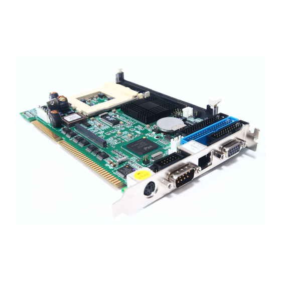
Page 13: Main Board Layout
Peak 602VL User's Guide Rev. B0 Dec. 2000 Chapter 2 Jumpers Switches and Connectors 2-1 Main Board Layout (J5) (CON2) (J2) (J4) J3:JST KEYBOARD CONNECTOR Jumpers Switch and Connectors... - Page 14 Peak 602VL User's Guide Rev. B0 Dec. 2000 2-2 Jumpers / Switches / Connectors JP1: RTC RESET 1-2 Short NORMAL 2-3 Short RTC RESET JP2: NEXCOM PCI PERIPHERAL CONNECTOR PIN No. Description PIN No. Description Ground AD10 AD11 AD12 AD13...
- Page 15 Peak 602VL User's Guide Rev. B0 Dec. 2000 GNT#2 Ground PCI Clock PCI Clock PCIRST# Lock# IRQ#A IRQ#B IRQ#C IRQ#D JP5: KEYBOARD LOCK PIN 1 PIN 2 PIN 3 PIN 4 KEYBOARD LOCK PIN 5 JP6: HDD LED PIN 1...
- Page 16 Peak 602VL User's Guide Rev. B0 Dec. 2000 JP11: SUSPEND LED CONNECTOR PIN 1 PIN 2 SUSLED JP12: TEMPERATURE CONNECTOR PIN 1 RESISTOR INPUT PIN 2 RESISTOR INPUT JP15: LAN ISOLATOR LAN ISOLATOR NORMAL JP17: LAN SPEED LED CONNECTOR PIN 1 3.3V Power...
- Page 17 Peak 602VL User's Guide Rev. B0 Dec. 2000 SMB1: SM-BUS CONNECTOR PIN 1 SM BUS CLOCK PIN 2 PIN 3 PIN 4 SM BUS DATA PIN 5 S2: CASEOPEN PIN 1 PIN 2 CASEOPEN SW3: FSB /SYSTEM MEMORY CPU DEFAULT...
- Page 18 Peak 602VL User's Guide Rev. B0 Dec. 2000 RJ45 CONNECTOR PIN No. Description TXO+ TXO- RXI+ TERMPLANE TERMPLANE RXI - TERMPLANE TERMPLANE JST KEYBOARD CONNECTOR PIN 1 KEYBOARD CLOCK PIN 2 KEYBOARD DATA PIN 3 PIN 4 PIN 5 PS2 KEYBOARD/MOUSE CONNECTOR...
-
Page 19: Com Port
Peak 602VL User's Guide Rev. B0 Dec. 2000 USB CONNECTOR PIN 1 PIN 2 SD0- PIN 3 SD0+ PIN 4 SD1- PIN 5 SD1+ PIN 6 COM PORT 1: COM PORT 1 D-SUB 9 PIN COM PORT CONNECTOR PIN No. - Page 20 Peak 602VL User's Guide Rev. B0 Dec. 2000 CON2: CON2 D-SUB 15 PIN VGA CONNECTOR PIN No. Description GREEN BLUE Ground Ground Ground Ground Ground Display Data Channel data Horizontal Sync Vertical Sync Display Data Channel clock Jumpers Switch and Connectors...
- Page 21 Peak 602VL User's Guide Rev. B0 Dec. 2000 FDC1: HEADER 17*2 PIN FLOPPY DISK CONNECTOR PIN No. Description PIN No. Description Ground Density Select bit 0 Ground Density Select bit 1 Ground Index# Ground Motor Enabled A# Ground Drive Select B#...
- Page 22 Peak 602VL User's Guide Rev. B0 Dec. 2000 IDE1: HEADER 20*2 PIN ATA100/66/33 HDD CONNECTOR PIN No. Description PIN No. Description Reset# Ground Data 7 Data 8 Data 6 Data 9 Data 5 Data 10 Data 4 Data 11 Data 3...
-
Page 23: Parallel Port
Peak 602VL User's Guide Rev. B0 Dec. 2000 PARALLEL PORT: PARALLEL PORT: HEADER 13*2 PIN PARALLEL PORT CONNECTOR PIN No. Description PIN No. Description Strobe# Data 0 Data 1 Data 2 Data 3 Data 4 Data 5 Data 6 Data 7... -
Page 24: Chapter 3 Capability Expanding
Peak 602VL User's Guide Rev. B0 Dec. 2000 Chapter 3 Capability Expanding This chapter explains how you can expand capability of your CPU board in such aspects as system memory and CPU. 3-1 System Memory Peak602VL support 2 slots for 168-pin 3.3V Non-registered DIMM modules, providing support for up to 512MB of main memory using DIMM modules from 8MB to 256MB. -
Page 25: Change Cpu
Peak 602VL User's Guide Rev. B0 Dec. 2000 3-2 Change CPU To change the CPU, pull the handling bar of the socket upward to the other end to loosen the socket's openings. Carefully lift the existing CPU up to remove it from the socket. -
Page 26: Chapter 4 Award Bios Setup
Peak 602VL User's Guide Rev. B0 Dec. 2000 Chapter 4 AWARD BIOS Setup Award's BIOS ROM has a built-in Setup program that allows users to modify the basic system configuration. This type of information is stored in battery-backed RAM (CMOS RAM) so that it retains the Setup information when the power is turned off. -
Page 27: Control Keys
Peak 602VL User's Guide Rev. B0 Dec. 2000 Control Keys Move to previous item Up arrow Move to next item Down arrow Move to the item in the left hand Left arrow Move to the item in the right hand... -
Page 28: Getting Help
Peak 602VL User's Guide Rev. B0 Dec. 2000 Getting Help Main Menu The on-line description of the highlighted setup function is displayed at the bottom of the screen. Status Page Setup Menu/Option Page Setup Menu Press <F1> to pop up a small help window that describes the appropriate keys to use and the possible selections for the highlighted item. -
Page 29: The Main Menu
Peak 602VL User's Guide Rev. B0 Dec. 2000 The Main Menu Once you enter Award BIOS CMOS Setup Utility, the Main Menu (Figure 1) will appear on the screen. The Main Menu allows you to select from ten setup functions and two exit choices. Use arrow keys to select among the items and press <Enter>... - Page 30 Peak 602VL User's Guide Rev. B0 Dec. 2000 PnP/PCI Configuration This entry appears if your system supports PnP / PCI Configuration. See Page 4-25 for details. PC health Status Display CPU/System Temperature, Fan speed and Voltages Value. See Page 4-27 for details.
- Page 31 Peak 602VL User's Guide Rev. B0 Dec. 2000 Standard CMOS Features The items in Standard CMOS Setup Menu are divided into 11 categories. Each category includes no, one or more than one setup items. Use the arrow keys to highlight the item and then use the <PgUp> or <PgDn>...
- Page 32 Peak 602VL User's Guide Rev. B0 Dec. 2000 1.2M, 5.25 in 720K, 3.5 in 1.44M, 3.5 in 2.88M, 3.5 in 3 Mode floppy disk drives (FDD) are 3 1/2” drives used in Japanese computer systems. Floppy Mode Disabled, Drive A, Drive B,...
- Page 33 Peak 602VL User's Guide Rev. B0 Dec. 2000 IDE Adapters The IDE adapters control the hard disk drive. Use a separate sub menu to configure each hard disk drive. Use the legend keys to navigate through this menu and exit to the main menu. Use below table to configure the hard disk.
-
Page 34: Advanced Bios Features Setup Menu
Peak 602VL User's Guide Rev. B0 Dec. 2000 Advanced BIOS Features Setup Menu This section allows you to configure your system for basic operation. You have the opportunity to select the system’s default speed, boot-up sequence, keyboard operation, shadowing and security. - Page 35 Peak 602VL User's Guide Rev. B0 Dec. 2000 CPU Internal Cache/External Cache These two categories speed up memory access. However, it depends on CPU/chipset design. The default value is Enable. If your CPU without Internal Cache then this item “CPU Internal Cache” will not be show.
- Page 36 Peak 602VL User's Guide Rev. B0 Dec. 2000 Gate A20 Option Select if chipset or keyboard controller should control GateA20. Normal A pin in the keyboard controller controls GateA20 Fast Lets chipset control Gate A20 Typematic Rate Setting Key strokes repeat at a rate determined by the keyboard controller. When enabled, the typematic rate and typematic delay can be selected.
- Page 37 Peak 602VL User's Guide Rev. B0 Dec. 2000 HDD S.M.A.R.T. Capability S.M.A.R.T. (Self-Monitoring, Analysis and Reporting Technology) is a technology developed to manage the reliability of the hard disk by predicting future device failures. The hard disk needs to be S.M.A.R.T.
-
Page 38: Advanced Chipset Features Setup Menu
Peak 602VL User's Guide Rev. B0 Dec. 2000 Advanced Chipset Features Setup Menu Since the features in this section are related to the chipset in the CPU board and all are optimized, you are not recommended to change the default settings in the setup table, unless you know very detailed of the chipset features. - Page 39 Peak 602VL User's Guide Rev. B0 Dec. 2000 The Choice: 5/7, 7/9. SDRAM RAS-to-CAS Delay This field let’s you insert a timing delay between the CAS and RAS strobe signals, used when DRAM is written to, read from, or refreshed.
- Page 40 Peak 602VL User's Guide Rev. B0 Dec. 2000 Delayed Transaction The chipset has an embedded 32-bit posted write buffer to support delay transactions cycles. Select Enabled to support compliance with PCI specification version 2.1. The Choice: Enabled, Disabled AGP Graphics Aperture Size This field determines the effective size of the Graphic Aperture used for a particular GMCH configuration.
- Page 41 Peak 602VL User's Guide Rev. B0 Dec. 2000 RAS# Timing This item controls RAS# active to Protegra, and refresh to RAS# active delay ( in local memory clocks). The Choice: Fast, Slow. RAS# Precharge Timing This item controls RAS# precharge (in local memory clocks).
-
Page 42: Integrated Peripherals
Peak 602VL User's Guide Rev. B0 Dec. 2000 Integrated Peripherals Onboard LAN Boot ROM Decide whether to invoke the boot ROM of the onboard LAN chip. The choice: Enable, Disabled. 4-17 BIOS Setup... - Page 43 Peak 602VL User's Guide Rev. B0 Dec. 2000 Onboard SCSI Boot ROM Decide whether to invoke the boot ROM of the onboard SCSI. The choice: Enabled, Disabled. On-Chip Primary/Secondary PCI IDE The chipset contains a PCI IDE interface with support for two IDE channels. Select Enabled to activate the primary/secondary IDE interface.
- Page 44 Peak 602VL User's Guide Rev. B0 Dec. 2000 The Choice: Enabled, Disabled. Init Display First This item allows you to decide to active whether PCI Slot or on-chip VGA first The Choice: PCI Slot, Onboard. IDE HDD Block Mode Block mode is also called block transfer, multiple commands, or multiple sector read/write. If your IDE hard drive supports block mode (most new drives do), select Enabled for automatic detection of the optimal number of block read/writes per sector the drive can support.
- Page 45 Peak 602VL User's Guide Rev. B0 Dec. 2000 ECP Mode Use DMA Select a DMA channel for the parallel port for use during ECP mode. The Choice: 3, 1. 4-20 BIOS Setup...
-
Page 46: Power Management Setup
Peak 602VL User's Guide Rev. B0 Dec. 2000 Power Management Setup The Power Management Setup allows you to configure your system to most effectively save energy while operating in a manner consistent with your own style of computer use. ACPI Function This item allows you to Enable/Disable the Advanced Configuration and Power Interface (ACPI). - Page 47 Peak 602VL User's Guide Rev. B0 Dec. 2000 Power Management This category allows you to select the type (or degree) of power saving and is directly related to the following modes: 1. HDD Power Down 2. Doze Mode 3. Suspend Mode There are four selections for Power Management, three of which have fixed mode settings.
- Page 48 Peak 602VL User's Guide Rev. B0 Dec. 2000 Suspend Mode When enabled and after the set time of system inactivity, all devices except the CPU will be shut off. The Choice: Enabled, Disabled. HDD Power Down When enabled and after the set time of system inactivity, the hard disk drive will be powered down while all other devices remain active.
- Page 49 Peak 602VL User's Guide Rev. B0 Dec. 2000 PM Events (Reload Global Timer Events) PM events are I/O events whose occurrence can prevent the system from entering a power saving mode or can awaken the system from such a mode. In effect, the system remains alert for anything which occurs to a device which is configured as Enabled, even when the system is in a power down mode.
-
Page 50: Pnp/Pci Configuration
Peak 602VL User's Guide Rev. B0 Dec. 2000 PnP/PCI Configuration This section describes configuring the PCI bus system. Peripheral Component Interface, is a system which allows I/O devices to operate at speeds nearing the speed the CPU itself uses when communicating with its own special components. - Page 51 Peak 602VL User's Guide Rev. B0 Dec. 2000 Resources Controlled by The Award Plug and Play BIOS has the capacity to automatically configure all of the boot and Plug and Play compatible devices. However, this capability means absolutely nothing unless you are using a Plug and Play operating system such as Windows95.
-
Page 52: Pc Health Status
Peak 602VL User's Guide Rev. B0 Dec. 2000 PC Health Status Shutdown Temperature This item allows you to set up the CPU shutdown Temperature. This item only effective under Windows 98 ACPI mode. The Choice: Disabled, 60°C/140°F, 65°C/149°F. 4-27 BIOS Setup... -
Page 53: Frequency/Voltage Control
Peak 602VL User's Guide Rev. B0 Dec. 2000 Frequency/Voltage Control Auto Detect DIMM/PCI Clk When enabled, this item will auto detect if the DIMM and PCI socket have devices and will send clock signal to DIMM and PCI devices. When disabled, it will send the clock signal to all DIMM and PCI socket. -
Page 54: Supervisor/User Password Setting
Peak 602VL User's Guide Rev. B0 Dec. 2000 Supervisor/User Password Setting You can set either supervisor or user password, or both of then. The differences between are: supervisor password : can enter and change the options of the setup menus. -
Page 55: Power-On Boot
Peak 602VL User's Guide Rev. B0 Dec. 2000 Power-On Boot After you have made all the changes to CMOS values and the system cannot boot with the CMOS values selected in Setup, restart the system by turning it OFF then ON or Pressing the "RESET" button on the system case. You may also restart by simultaneously press <Ctrl>, <Alt>, and <Delete>... -
Page 56: Bios Reference - Post Message
Peak 602VL User's Guide Rev. B0 Dec. 2000 4-2 BIOS Reference - POST Message During the Power On Self Test (POST), if the BIOS detects an error requiring you to do something to fix, it will either sound a beep code or display a message. - Page 57 Peak 602VL User's Guide Rev. B0 Dec. 2000 DISPLAY TYPE HAS CHANGED SINCE LAST BOOT Since last powering off the system, the display adapter has been changed. You must configure the system for the new display type. EISA Configuration Checksum Error PLEASE RUN EISA CONFIGURATION UTILITY The EISA non-volatile RAM checksum is incorrect or cannot correctly read the EISA slot.
- Page 58 Peak 602VL User's Guide Rev. B0 Dec. 2000 Hard Disk(s) fail (08) Sector Verify failed. Invalid EISA Configuration PLEASE RUN EISA CONFIGURATION UTILITY The non-volatile memory containing EISA configuration information was programmed incorrectly or has become corrupt. Re-run EISA configuration utility to correctly program the memory.
- Page 59 Peak 602VL User's Guide Rev. B0 Dec. 2000 OFFENDING SEGMENT: This message is used in conjunction with the I/O CHANNEL CHECK and RAM PARITY ERROR messages when the segment that has caused the problem has been isolated. PRESS A KEY TO REBOOT This will be displayed at the bottom screen when an error occurs that requires you to reboot.
-
Page 60: Bios Reference - Post Codes
Peak 602VL User's Guide Rev. B0 Dec. 2000 4-3 BIOS Reference - POST Codes POST (hex) Description Test CMOS R/W functionality. Early chipset initialization: -Disable shadow RAM -Disable L2 cache (socket 7 or below). -Program basic chipset registers. Detect memory -Auto-detection of DRAM size, type and ECC. - Page 61 Peak 602VL User's Guide Rev. B0 Dec. 2000 POST (hex) Description for ESCD & DMI support. Reserved Use walking 1’s algorithm to check out interface in CMOS circuitry. Also set real-time clock power status, and then check for override. Reserved Program chipset default values into chipset.
- Page 62 Peak 602VL User's Guide Rev. B0 Dec. 2000 POST (hex) Description Reserved Reserved Reserved Initialize INT 09h buffer Reserved 1. Program CPU internal MTRR (P6 & PII) for 0-640KB memory address. 2. Initialize the APIC for Pentium class CPU. 3. Program early chipset according to CMOS setup. Example: On-Board IDE controller.
- Page 63 Peak 602VL User's Guide Rev. B0 Dec. 2000 POST (hex) Description Reserved. Test 8259 interrupt mask bits for channel 2. Reserved. Reserved. Test 8259 functionality. Reserved. Reserved. Reserved. Initialize EISA slot. Reserved. 1. Calculate total memory by testing the last double word of each 64KB page.
- Page 64 Peak 602VL User's Guide Rev. B0 Dec. 2000 POST (hex) Description Initialize the combined Trend Anti-Virus code. Reserved. (Optional Feature). Show message for entering AWDFLASH.EXE from FDD (optional). Reserved. 1. Initialize Init_Onboard_Super_IO switch. 2. Initialize Init_Onboard_AUDIO switch. Reserved Reserved Okay to enter Setup utility; i.e. not until this POST stage users can enter the CMOS setup utility.
- Page 65 Peak 602VL User's Guide Rev. B0 Dec. 2000 POST (hex) Description (Optional Feature). Enter AWDFLASH.EXE if : -AWDFLASH is found in Floppy Drive. -“ALT+F2” is pressed. Reserved. Detect & install all IDE devices: HDD, LS120, ZIP, CDROM….. Reserved. Detect Serial ports & Parallel ports.
- Page 66 Peak 602VL User's Guide Rev. B0 Dec. 2000 POST (hex) Description 7. Initialize APM. 8. Clear noise of IRQs. Reserved. Reserved. Reserved. Reserved. Reserved. Reserved. Reserved. Read HDD boot sector information for Trend Anti-Virus code. 1. Enable L2 cache. 2. Program boot up speed.
- Page 67 Peak 602VL User's Guide Rev. B0 Dec. 2000 This page is intentionally left blank. 4-42 BIOS Setup...
-
Page 68: Appendix
Peak 602VL User's Guide Rev. B0 Dec. 2000 Appendix Appendix A Watch Dog Timer Watch Dog Timer Working Procedure The Watch Dog Timer (WDT) is the special hardware device. The WDT function is to monitor the computer system whether work normally, otherwise, it will have some measures to fix up the system. - Page 69 Peak 602VL User's Guide Rev. B0 Dec. 2000 Watch Dog Timer Control Register The Watch Dog Timer Control Register is to control the WDT working mode. You can write the value to WDT Configuration Port. The following is the Control Register bit definition.
- Page 70 Peak 602VL User's Guide Rev. B0 Dec. 2000 Watch Dog Timer Programming Procedure • • • • Power on or reset the system The initial value of WDT Control Register (D4~D0) is zero, when power is on or reset the system. The...
- Page 71 Peak 602VL User's Guide Rev. B0 Dec. 2000 • • • • Clear the WDT Repeatedly read WDT Configuration Port and the interval cannot be longer than the preset time, otherwise, the WDT will generate NMI or Reset signal for the system.
- Page 72 Peak 602VL User's Guide Rev. B0 Dec. 2000 After finishing the above setting, you must be output for the Control Register’s value to the WDT Configuration Port. Then WDT will start according to the above setting. dx, F2h dx, F2h ;...
Need help?
Do you have a question about the Peak 602VL and is the answer not in the manual?
Questions and answers