
Related Manuals for Nexcom EBC 300 Series


Summary of Contents for Nexcom EBC 300 Series
- Page 1 Single Board Computer EBC 300 Series User’s Manual 07-13-2006 Build Nov-15-2006 Edit EBC 300 User’s Manual Preface...
-
Page 2: Preface
Any implied warranties of merchantability of fitness for any particular purpose is also disclaimed. Acknowledgements The EBC 300 series is a trademark of NEXCOM international CO., LTD. All other product names mentioned herein are registered trademarks of their respective owners. Regulatory Compliance Statements This section provides the FCC compliance statement for Class A devices and describes how to keep the system CE compliant. -
Page 3: Ce Certification
CE Certification The product(s) described in this manual complies with all applicable European Union (CE) directives if it has a CE marking. For computer systems to remain CE compliant, only CE-compliant parts may be used. Maintaining CE compliance also requires proper cable and cabling techniques. WARNINGS Read and adhere to all warnings, cautions, and notices in this guide and the documentation supplied with the chassis, power supply, and accessory... -
Page 4: Table Of Contents
Table of Content Preface……………...……………..……………………………………….………….……..……………..2 Copyright………………..……………………………………….……………………………………..Disclaimer………………………..………………………………..…………………………………….. Acknowledgements……………………………………………..……………………………..…..…… Regulatory Compliance Statements……………………..…………………………………….……………2 Federal Communications Commission (FCC) For Class A Device……………..……….…………..…..…1 CE Certification………………………………………………………………………….……….………...3 Safety Information……………………………………………………………………….………..………..3 Table of Content………………………………………………………………………………….…………4 Chapter 1 General Information 1.1 Main Feature…………………………………………………….…………………………….……….. 7 1.2 Specifications……………………………………………………..……………………………………. 7 1.3 Power Consumption Measurement…………………..…………………………………………………10 1.4 Board Layout…………………………………………………………………….………………….….10 Chapter 2Jumper Setting 2.1 Before You Begin……………………………………………..….……………………………………12... -
Page 5: Chapter 1 General Information
Chapter 1 General Information EBC 300 User’s Manual Chapter 1... -
Page 6: Main Feature
1.1 Main Feature Support Intel Celeron M 600MHz processor with 512K L2 cache and 400MHz FSB Support Intel® Pentium® M processor or Intel® Celeron® M processor in 478-pin, Micro-FCPGA package (mPGA479M Socket) Intel® 82852GM and Intel® ICH-4 chipsets • Onboard 256 MB Non-ECC DDR 200/266/333/400 SDRAM •... - Page 7 Award system BIOS - ACPI: Only support Software Shutdown by 5Vsb Provided (S0 /S5 only) - Advanced Power Management support - 4M bits flash ROM Support Pentium M Speed Step (Customized by Nexcom) BIOS Chipset - Intel® 82852GM - ICH-4 - Realtek®...
- Page 8 - Internal CompactFlash socketx1 Support One Type II CompactFlash Card (Secondary) - On Board Power LED and HDD Active LED Pin Header Audio - REALTEK ALC655-LF AC97 CODEC - Microphone in, Speaker out (external) SIO× 1, with 1x16C550 UARTs, One DB9 Connector - USB2.0 connector x 6 (two direct output, 4 from Jst Box Header) - HDD: Support IDE with 44 pin connector ×...
-
Page 9: Ordering Information
- Board-level operating temperatures: -20°C to 60°C Environments - Storage temperatures: -20°C to 80°C - Relative humidity: 10% to 90% (Non-condensing) Certification - CE - FCC Class A Ordering Information EBC 300-C65-256M 3.5” Low Power Embedded Board with Celeron M 600MHZ 512KB L2 on Board with VGA/ LVDS/Audio/COM/ USB2.0 / Gigabit LAN EBC 300-SKT-256 3.5”... -
Page 10: Board Layout
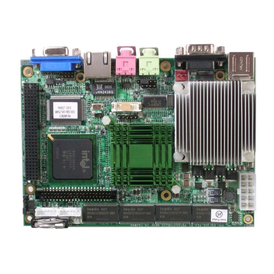
1.4 Board Layout Figure 1.2: Overview of EBC 300 EBC 300 User’s Manual Chapter 1... -
Page 11: Chapter 2Jumper Setting
Chapter 2 Jumper Setting EBC 300 User’s Manual Appendix B... -
Page 12: Before You Begin
This chapter of the User’s Manual describes how to set jumpers. Note: The procedures that follow are generic for all EBC 300 series. 2.1 Before You Begin Ensure you have a stable, clean working environment. Dust and dirt can get into components and cause a malfunction. -
Page 13: Setting Jumpers
2.3 Setting Jumpers A jumper is the simplest kind of electric switch. It consists of two metal pins and a cap. When setting the jumpers, ensure that the jumper caps are placed on the correct pins. When the jumper cap is placed on both pins, the jumper is SHORT. -
Page 14: Location Of Jumpers
2.4 Location of Jumpers =PIN 1 JP10 CON1 FAN1 USB1 LAN1 COM1 VGA1 Figure 2-1: Jumper Location 2.5 Functions of Jumpers and Connectors J1: 1x6 2.0mm JST Connector for USB Port 2-3 Pin No Definition VCC5 J2: 1x6 2.0mm JST Connector for USB Port 4-5 Pin No Definition VCC5... - Page 15 JP1: 1x2 2.0mm Pin Header for AT mode Pin No Definition PSON# JP2: 1x2 2.54mm Pin Header for IDE LED Pin No Definition VCC3 IDE_LED# JP3: 1x2 2.54mm Pin Header for Power LED Pin No Definition VCC5 JP4: 1x2 2.54mm Pin Header for Power Button Pin No Definition PWRBNT#...
- Page 16 JP8: 2x4 2.0mm Pin Header for GPIO Function Pin No. Description Pin No. Description D_IN1 D_OUT1 D_IN2 D_OUT2 D_IN3 D_OUT3 D_IN4 D_OUT4 JP9 : 1x3 2.0mm Pin Header for On Board RTC Pin No Definition *1, 2 Short by Operation Mode wire-wrap 2, 3 Short by wire-wrap Clear CMOS...
- Page 17 CN3: 2x10 Panel Connector for LVDS interface (18bit) Pin No. Description Pin No. Description LVDS_DDCPCLK LVDS_DDCPDATA PANEL1_VDD LVDS_YAP0 LVDS_YAP3 LVDS_YAM0 LVDS_YAM3 PANEL1_VDD LVDS_YAP1 LVDS_CLKAP LVDS_YAM1 LVDS_CLKAM PANEL1_BACKLIGHT LVDS_YAP2 PANEL1_BACKLIGHT LVDS_YAM2 CN4: 2x22 2.0mm Box Header for IDE Device Pin No Definition Pin No Definition...
- Page 18 COM1: SIO Connector Serial Port 1 Pin No. Description Pin No. Description SP_DCD2 SP_RXD2 SP_TXD2 SP_DTR2 SP_DSR2 SP_RTS2 SP_CTS2 SP_RI2 IDE1: Compact Flash Socket For CF Device Pin No Definition Pin No Definition CS0# VCC5 CD2# CD1# CS1# IOR# IOW# VCC5 IRQ15 VCC5...
- Page 19 USB1: USB Connector for USB Port 0-1 Pin No Definition Pin No Definition VCC5 VCC5 VGA1: DB-15 Connector for CRT Interface Definition Pin No Definition ANA-GND ANA-GND GREEN DDCDAT ANA-GND BLUE HSYNC VSYNC DIG-GND DIG-GND DDCCLK CON1: ATX Power Connector Pin No Definition Pin No...
- Page 20 LAN1: RJ45 Connector for LAN Interface Pin No Definition Pin No Definition TXD0P TXD0N TXD1P TXD2P TXD2N TXD1N TXD3P TXD3N LAN_SorL_LED +3.3VSBY LAN_LINK_LED LAN_ACT_LED LGND LGND EBC 300 User’s Manual Appendix B...
-
Page 21: Chapter 3 Expansion
Chapter 3 Expansion EBC 300 User’s Manual Appendix B... -
Page 22: System Memory
3.1 System Memory EBC 300 incorporates onboard 256 MB Non-ECC DDR SDRAM supporting frequencies from 200/266/333 up to 400. 3.2 Installing Compact Flash 1. To install a Compact Flash memory card into EBC 300, align the notches on the card with the Compact Flash socket in the EBC 300.
Need help?
Do you have a question about the EBC 300 Series and is the answer not in the manual?
Questions and answers