
Related Manuals for Nexcom EBC 500 Series


Summary of Contents for Nexcom EBC 500 Series
- Page 1 Single Board Computer EBC 500 Series User’s Manual 10-20-2006 Build EBC 500 User’s Manual Table of Content...
-
Page 2: Preface
Any implied warranties of merchantability of fitness for any particular purpose is also disclaimed. Acknowledgements The EBC 500 series is a trademark of NEXCOM international CO., LTD. All other product names mentioned herein are registered trademarks of their respective owners. Regulatory Compliance Statements This section provides the FCC compliance statement for Class A devices and describes how to keep the system CE compliant. -
Page 3: Ce Certification
measures) at their own expense. CE Certification The product(s) described in this manual complies with all applicable European Union (CE) directives if it has a CE marking. For computer systems to remain CE compliant, only CE-compliant parts may be used. Maintaining CE compliance also requires proper cable and cabling techniques. -
Page 4: Table Of Contents
Table of Content Preface Copyright Disclaimer Acknowledgements Regulatory Compliance Statements Federal Communications Commission (FCC) For Class A Device CE Certification Safety Information Table of Content Chapter 1 General Information 1.1 Main Feature 1.2 Specifications 1.3 Power Consumption Measurement 1.4 Board Layout 1.5 Board Dimensions Chapter 2Jumper Setting 2.1 Before You Begin... -
Page 5: Chapter 1 General Information
新漢電腦股份有限公司 EBC / ICES/ ICEB… NEXCOM International Co., Ltd. Chapter 1 General Information 8.5X11 Q410000-03AA... -
Page 6: Product Overview
新漢電腦股份有限公司 EBC / ICES/ ICEB… NEXCOM International Co., Ltd. 1.1 Product Feature Intel Core Solo & Core Duo and Core 2 Duo Processor Family support Intel 945GM Chipsets Two 240-pin DDR2 DIMM Socket support un-buffered non-ECC DDR2 400/533/667 up to 4GB... -
Page 7: Block Diagram
新漢電腦股份有限公司 EBC / ICES/ ICEB… NEXCOM International Co., Ltd. Block Diagram: 8.5X11 Q410000-03AA... -
Page 8: Specifications
1.2 Specification: *General Intel® Core Solo and Core Duo family processors Core 2 Duo family CPU (optional) Front Side Bus 533/667 MHz Chipset Intel 945GM and ICH7-DHM 2 x 240-pin DIMM socket, up to 4GB un-buffered non-ECC DDR 533/667 Memory SDRAM Super I/O ITE 8712F... - Page 9 Extra (External) LED: 2 x 4 pin header *Audio Realtek RTL655 CODEC for AC97 v2.1 CODEC AC97 Audio CODEC Line in with pin header Microphone in and Speaker out Interface *I/O Interface 6 x USB 2.0 port (2 on front, 4 on Board by one 2.0 mm JST USB 2.0 Connectors), bandwidth: 480 Mb/s SIO×...
-
Page 10: Ordering Information
Ordering Information: 5.25” Embedded Board supporting Intel Core Solo, Core Duo and EBC 500 Core 2 Duo CPU w/VGA/ Dual LVDS/Audio/4 COMs/6 USB2.0 /Dual (P/N: 1E00050000X0) Gigabit LAN 1.3 Power Consumption Measurement Chipset Vcore +1.8V +0.9V +1.5V +2.5V +3.3V +1.2V +3.3V +5VS Yonah +1.05... -
Page 11: Board Layout
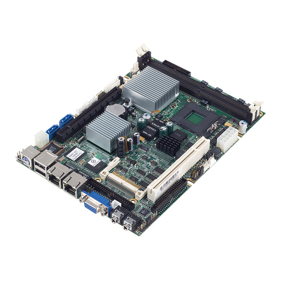
1.4 Board Layout Figure 1.2: Overview of EBC 500 EBC 500 User’s Manual Chapter 1... -
Page 12: Board Dimensions
1.5 Board Dimensions Figure 1.3: Mechanical Drawing of the EBC 500 EBC 500 User’s Manual Chapter 1... - Page 13 Chapter 2 Jumper Setting EBC 500 User’s Manual...
-
Page 14: Before You Begin
This chapter of the User’s Manual describes how to set jumpers. Note: The procedures that follow are generic for all EBC 500 series. 2.1 Before You Begin Ensure you have a stable, clean working environment. Dust and dirt can get into components and cause a malfunction. -
Page 15: Setting Jumpers
2.3 Setting Jumpers A jumper is the simplest kind of electric switch. It consists of two metal pins and a cap. When setting the jumpers, ensure that the jumper caps are placed on the correct pins. When the jumper cap is placed on both pins, the jumper is SHORT. If you remove the jumper cap, or place the jumper cap on just one pin, the jumper is OPEN. -
Page 16: Location Of Jumpers
2.4 Location of Jumpers COM x 4 CON 1 (ATX Power CON.) JP13 JP14 JP20 Speaker DIMM Compact Flash =PIN 1 JP15 JP16 JP17 LAN1 LAN2 (INTEL,ICH7) (INTEL,945GM) USBx CON 2 (ATX AUX JP12 Power CON.) JP9 PCI-e x 16 Slot JP19 LVDS LVDS... -
Page 17: Function Of Jumper
2.5 Functions of Jumpers and Connectors (1) SATA1/SATA0 connector (J8,J9) A . Connector size : 7 Pin , 1.27mm ,180°, SATA Connector B . Connector location C. Connector pin definition Definition Definition SATA_RXN SATA_TXP SATA_RXP SATA_TXN (2) PIO Connector (CN1) A . - Page 18 (3) SIO Connector (CN6) A . Connector size: 2 X 20 = 40 Pin ,2.0 mm, 180° ,BOX Header B . Connector location C . Connector pin definition Definition Definition DCD1 DCD3 DSR1 DSR3 RXD1 RXD3 RTS1 RTS3 TXD1 TXD3 CTS1 CTS3 DTR1...
- Page 19 (5) SYSTEM FAN1/FAN2 Connector(J1 , J5) A . Connector size : 1 X 3 = 3 Pin , 2.54mm ,180°, FAN Connector B . Connector location C . Connector pin definition Definition Definition Sense +12V (6) USB 2.0 , 0/1/4/5 Connector (J4 , J6 ) A .
- Page 20 (8) IDE Connector Primary (CN8) A . Connector size : 2 x 22 = 44pins,2.0mm, 180°,BOX Header B . Connector location C. Connector pin definition Definition Definition Reset# IOW# Data 7 IOR# Data 8 Data 6 IOCHRDY Data 9 Data 5 DMA ACK# Data 10 Data 4...
- Page 21 (9) Compact Flash Connector (CN7) A . Connector size : Compact Flash Socket 50 Pin Connector B . Connector location C . Connector pin definition Definition Definition Data 3 Data 11 Data 4 Data 12 Data 5 Data 13 Data 6 Data 14 Data 7 Data 15...
- Page 22 (10) GPIO (J10) A . Connector size : 2X5 = 10 PIN , 2.0mm , 180° , PIN Header B . Connector location C . Connector pin definition Definition Pin Definition GP25_D_OUT1(PIN22) GP22_D_IN2(PIN25) GP20_D_IN0(PIN27) GP26_D_OUT2(PIN21) GP24_D_OUT0(PIN23) GP23_D_IN3(PIN24) GP21_D_IN1(PIN26) GP27_D_OUT3(PIN20) *Digital I/O Used Port 801 Output Input GP24_D_OUT0(PIN23)
- Page 23 (13) 82573L LAN1 /LAN2 LINK 1000LED (JP17/JP19) A . Connector size : 1X2 = 2 PIN , 2.54mm , 180° , PIN Header B . Connector location C .Connector pin definition Pin Definition Pin Definition +3VSB Speed1000# (14) 82573L LAN1 / LAN2 Activity LED (JP16/JP18) A .
- Page 24 (17) Key board + mouse Connector(KM1) A . Connector size : MINI DIN 6 Pin Connector B . Connector location C .Connector pin definition Pin Definition Pin Definition Keyboard Data 5 +5VSB Mouse Data Keyboard Clock Mouse Clock (18) 82573L LAN1 / LAN2 Connector (CN10 , CN11) A .
- Page 25 (20) RTC Clear (JP6) A . Connector size : 1X3 = 3 PIN , 2.54mm , 180° , PIN Header B . Connector location C . Connector pin definition Normal Clear CMOS *1-2 * = DEFAULT SET (21) CF Card Master/Slave Select (JP14) A .
- Page 26 (23) Panel Voltage Select(JP1) A . Connector size : 1 X 3 = 3 PIN , 2.54mm , 180° , PIN Header B . Connector location C . Connector pin definition *2-3 Def. +3.3V * = DEFAULT SET (24) TV Output(JP2) A .
- Page 27 C . Connector pin definition Pin Definition Pin Definition HDD_ACTIVE# (27) SMBUS Connector(JP12) A . Connector size : 1X2 = 2 PIN , 2.54mm , 180° , PIN Header B . Connector location C . Connector pin definition Pin Definition Pin Definition SMB_CLK 2 SMB_DATA...
- Page 28 Pin Definition Pin Definition PWRBT (31) COM4 RS232 RI# Pin Power Select & RI# Pin Select(JP4) A . Connector size : 1X5 = 5 PIN , 2.54mm , 180° , PIN Header B . Connector location C . Connector pin definition Pin Definition Pin Definition RI4#_SELECT...
- Page 29 (33) POWER Connector (CON1) A . Connector size : 2X5 = 10PIN , 4.2mm , FEMALE B . Connector location C . Connector pin definition Pin Definition Pin Definition PSON# +5VSB +12V -12V (34) ATX AUX POWER Connector (CON2) A . Connector size : 2X2 = 2 PIN , 3.5mm , FEMALE r B .
-
Page 30: Power Consumption
2.6 Power consumption ( Unit : A ) Chipset Vcore +1.8V +0.9V +1.5V +2.5V +3.3V +1.2V +3.3V +5VS Yonah +1.05 CPU(1. Total Current 13.4 8.12 0.35 (Unit: A ) Total Watt 43.2 20.1 26.8 1.92 1.155 42.5 (Unit: W ) Transfer +12V 3VSB... -
Page 31: Chapter 3 Expansion
Chapter 3 Expansion EBC 500 User’s Manual... -
Page 32: System Memory
3.1 System Memory EBC 500 incorporates Intel 945GM chipset supports up to 4GB un-buffered non-ECC DDR 533/667 SDRAM 3.2 Installing DIMM To install DIMM 1. Make sure the two handles of the DIMM sockets are in the “open” position, i.e. the handles stay outward. - Page 33 3. Then press the DIMM module down right into the socket, until a click is heard. That means the two handles automatically locked the memory modules into the right position of the DIMM socket. Figure 3-3: How to Install DIMM (3) 4.
-
Page 34: Installing Compact Flash
3.3 Installing Compact Flash 1. To install a Compact Flash memory card into EBC 500, align the notches on the card with the Compact Flash socket in the EBC 500. Then firmly insert the card into the socket until it is completely seated. - Page 35 EBC 500 User’s Manual...
Need help?
Do you have a question about the EBC 500 Series and is the answer not in the manual?
Questions and answers