Table of Contents
Advertisement
Available languages
Available languages
AUTOMAZIONE PER CANCELLI SCORREVOLI CON MOTORE IN CORRENTE CONTINUA
AUTOMATION FOR SLIDING GATES WITH A DC POWERED MOTOR
AUTOMATISME POUR PORTAILS COULISSANTS AVEC MOTEUR À COURANT CONTINU
AUTOMATISIERUNG FÜR SCHIEBETORE MIT GLEICHSTROMMOTOR
AUTOMATIZACION PARA CANCELAS CORREDERAS CON MOTOR DE CORRIENTE CONTINUA
ITALIANO
ENGLISH
By CARDIN ELETTRONICA spa
Via Raffaello, 36
31020 San Vendemiano (TV) Italy
Tel:
+39/0438.401818
Fax:
+39/0438.401831
email (Italy):
Sales.office.it@cardin.it
email (Europe):
Sales.office@cardin.it
Http:
www.cardin.it
Pagina
2-5
Pagina
6
Pagina
7
Pagina
7
Pagina
8
Pagina
9
Pagina
10
Pagina
10
Pagina
10
Pagina
11
Pagina
12
Pagina
12
Pagina
13
Pagina
46
Page
2-5
Page
14
Page
15
Page
15
Page
16
Page
17
Page
18
Page
18
Page
18
Page
19
Page
20
Page
20
Page
21
Page
46
1
CODE
SERIES
ZVL317.03
SL
Questo prodotto è stato testato e collaudato nei laboratori della casa costruttrice, la quale ne ha verifi cato la perfetta
corrispondenza delle caratteristiche con quelle richieste dalla normativa vigente
This product has been tried and tested in the manufacturer's laboratory who have verifi ed that the product conforms
in every aspect to the safety standards in force.
Ce produit a été testé et essayé dans les laboratoires de la Maison Constructrice qui a pris soin de vérifi er la conformité de
ses caractéristiques avec les exigences des normes en vigueur.
Dieses Produkt wurde in den Werkstätten der Herstellerfi rma auf die perfekte Übereinstimmung ihrer Eigenschaften mit
den von den geltenden Normen vorgeschriebenen getestet und geprüft.
Este producto ha sido probado y ensayado en los laboratorios del fabricante, que ha comprobado la perfecta
correspondencia de sus caracteristicas con las que dispone la normativa vigente.
FRANÇAIS
DEUTSCH
ESPAÑOL
MODEL
DATE
402409
13-09-2001
101/SL402409
Page
2-5
Page
22
Page
23
Page
23
Page
24
Page
25
Page
26
Page
26
Page
26
Page
27
Page
28
Page
28
Page
29
Page
46
Seite
2-5
Seite
30
Seite
31
Seite
31
Seite
32
Seite
33
Seite
34
Seite
34
Seite
34
Seite
35
Seite
36
Seite
36
Seite
37
Seite
46
Página
2-5
Página
38
Página
39
Página
39
Página
40
Página
41
Página
42
Página
42
Página
42
Página
43
Página
44
Página
44
Página
45
Página
46
Advertisement
Table of Contents

Related Manuals for Cardin Elettronica 101/SL402409


Summary of Contents for Cardin Elettronica 101/SL402409
-
Page 1: Table Of Contents
By CARDIN ELETTRONICA spa CODE SERIES MODEL DATE Via Raffaello, 36 ZVL317.03 402409 13-09-2001 31020 San Vendemiano (TV) Italy Questo prodotto è stato testato e collaudato nei laboratori della casa costruttrice, la quale ne ha verifi cato la perfetta corrispondenza delle caratteristiche con quelle richieste dalla normativa vigente Tel: +39/0438.401818... -
Page 2: Installation Example
VERIFICHE PRELIMINARI - PRELIMINARY CHECKS - CONTRÔLES À EFFECTUER AVANT LE MONTAGE VORKONTROLLEN - PRUEBAS PREVIAS... -
Page 3: Impianto Tipo
IMPIANTO TIPO - INSTALLATION EXAMPLE - EXEMPLE D'INSTALLATION - ANLAGENART - INSTALACION ESTANDAR... - Page 4 SCHEMA ELETTRICO IMPIANTO TIPO - STANDARD WIRING DIAGRAM - SCHÉMA ÉLECTRIQUE DE L'EXEMPLE D'INSTALLATION ELEKTRISCHER SCHALTPLAN ANLAGENART - ESQUEMA ELECTRICO INSTALACION ESTANDAR Fuse T1.6A 220V~ LINE 220V~ TRF 220V~ TC TA 24V 12V 0 FTC-TX FTC-RX LEGENDA LEGEND NOMENCLATURE Lampeggiatore Flashing warning lights Clignoteur FTC-RX Fotocellula ricevitore...
- Page 5 COLLEGAMENTO SCHEDA CARICA BATTERIE 24V dc (OPZIONALE) - CONNECTING THE BATTERY CHARGER CARD 24V dc (OPTIONAL) BRANCHEMENT CARTE CHARGEUR DE BATTERIE 24V dc (EN OPTION) - KARTENANSCHLUSS BATTERIELADEGERÄT 24V dc (OPTIONAL) CONEXIÓN TARJETA CARGADOR DE BATERÍAS 24V dc (OPCIONAL) DC0303 CS1072B Fuse F1A Rd Rosso, red, rouge,...
-
Page 6: Avvertenze Importanti
Questo prodotto è stato progettato e fabbricato in tutte le sue parti a cura della legge N.46 del 5.3.1990) e richiede una buona conoscenza della della Cardin Elettronica la quale ne ha verifi cato la perfetta corrispondenza tecnica, esercitata in forma professionale e della normativa vigente. I delle caratteristiche con quelle richieste dalla normativa vigente. -
Page 7: Verifi Che Preliminari Di Montaggio
5) È buona norma segnalare l’automazione con targhe Controllare periodicamente lo stato di usura dei perni ed eventualmente ATTENZIONE di avvertenza (simili a quella in fi gura) che devono ingrassare le parti in moto (perni, cremagliera ecc), usando lubrifi canti che APERTURA AUTOMATICA mantengano uguali caratteristiche di attrito nel tempo e adatti a funzionare essere facilmente visibili. -
Page 8: Sblocco
Montaggio cremagliera SBLOCCO MANUALE • Per il fi ssaggio della cremagliera all’anta scorrevole procedere nel seguente modo: L'operazione di sblocco va fatta normalmente a motore fermo per - sbloccare il motoriduttore (fi g.11), appoggiare il primo elemento di mancanza di energia elettrica. cremagliera sul pignone e fi... -
Page 9: Programmatore Elettronico
* I LED sono accesi se la relativa sicurezza non è attivata (dipende dalla PROGRAMMATORE ELETTRONICO posizione dell'anta). Verifi care che l'attivazione delle sicurezze porti allo spegnimento del LED Programmatore per motore in corrente continua con ricevente incorporata, ad esse associato. che permette la memorizzazione di 300 codici utente (vedere "comando via radio", a pag.11). -
Page 10: Indicazioni Del Display
INDICAZIONI DEL DISPLAY (D1) PROCEDURA DI PROGRAMMAZIONE A) Impostazioni del programmatore allarme per entrambi i fi necorsa meccanici attivati contem- poraneamente Prima di iniziare accertarsi che l'anta sia chiusa, il errore sui parametri in memoria display a LED è spento e i LED L4,L5,L7,L8 siano tutti accesi. -
Page 11: Comando Via Radio
B) Programmazione del tempo di rallentamento Alla prima pressione del tasto "PROG" sul display appare il simbolo e inizia la programmazione del tempo di apertura, che viene calcolato La pressione del tasto "PROG" dal punto descritto nel riquadro 8 con l'anta in movimento; l'attivazione del fi necorsa di apertura determina porta alla fase di impostazione del tempo di rallentamento. -
Page 12: Modalità Di Funzionamento
A) Memorizzazione di un canale (fi g.12): COLLEGAMENTO ANTENNA PER MODULO RF A 433MHz 1. Premere il pulsante "P3" MEMO e tenerlo premuto: il LED "L2" lampeggia Il ricevitore è dotato di antenna propria, consistente in uno spezzone di fi lo lentamente. -
Page 13: Carica Batteria (Opzionale)
CARICA BATTERIA (OPZIONALE) Modalità di funzionamento Quando la tensione di rete è presente, i relays del carica-batterie sono normalmente eccitati e i due secondari del trasformatore vengono diret- tamente collegati ai faston della centralina. In assenza della tensione di rete, i relays tornano alla condizione di riposo, e la tensione di batteria viene applicata alla centralina, sia per quanto riguarda la parte logica che per quella di controllo del motore. -
Page 14: Important Remarks
This product and all its relative components has been designed and manufactured All materials used must be approved and must suit the environment in by Cardin Elettronica who have verifi ed that the product conforms in every which the installation is situated. -
Page 15: Preliminary Assembly Operations
5) The gate must be in full view when it is operating therefore controls Eventual repair work must be carried out by specialised personnel must be situated in a position where the operator using original spare parts. The appliance is not suitable for continuous can see the gate at all times. -
Page 16: Manual Release Mechanism
Fitting the toothed rack MANUAL RELEASE MECHANISM • To fi t the toothed rack to the sliding gate proceed as follows: - release the geared motor (fi g.11), lay the fi rst stretch of the Manual release is normally carried out with the power to the motor toothed rack on the pinion and fi... -
Page 17: Electronic Programmer
*The LEDs are "ON" if the relative security device is inactive (depends on the ELECTRONIC PROGRAMMER position of the door). Electronic programmer for a DC motor with an incorporated radio receiver Check that the activation of the safety devices switches the corresponding card, which allows the memorisation of 300 user codes (see "remote control"... -
Page 18: Indications On The Display
INDICATIONS ON THE DISPLAY (D1) PROGRAMMING PROCEDURE A) Setting the programmer alarm caused by two mechanical travel limits being acti- vated together Before commencing make sure that the door memorised parameter error is closed, the LCD display is off and the LEDS L4,L5,L7,L8 are all lit. -
Page 19: Remote Control
B) Programming the deceleration times The fi rst time you press the "PROG" button the symbol will appear on the display and the work time programming stage, which Pressing the "PROG" at the point described in fi g.8 will allow you is calculated while the gate is moving, will start;... -
Page 20: Function Modes
A) Memorising a channel (fi g.12): CONNECTING THE 433 MHZ MODULE ANTENNA 1. Press and hold down button "P3" MEMO: The LED "L2" will The receiver is supplied with its own antenna which consists of fl ash slowly. a piece of rigid wire 170mm in length. In alternative it is possible 2. -
Page 21: Battery Charger
BATTERY CHARGER (OPTIONAL) This device allows the SL402409 motor for sliding gates to work during blackouts. Warning! You may only use the battery charger with an electronic card which has a printed circuit number of 1038.02 or greater. Description When the power is switched on, the battery charger relays are activated and the two transformer secondaries are directly connected to the fastons on the main circuit board. -
Page 22: Consignes
Caractéristiques générales professionnelle pour l'installation des "appareils électriques" et requiert une Ce produit a été étudié et construit entièrement par la Sté Cardin Elettronica bonne connaissance de la technique appliquée professionnellement, ainsi qui a pris soin de vérifi er la conformité de ses caractéristiques avec les que des normes en vigueur. -
Page 23: Contrôles À Effectuer Avant Le Montage
5) Il est conseillé de signaler l'automatisation du portail par En cas de panne ou de mauvais fonctionnement, mettre l'appareil immédiatement ATTENTION des panneaux de signalisation (comme celui indiqué hors tension et contacter le service d'assistance technique. en fi gure) placés bien en vue. Dans l'hypothèse où Les éventuelles réparations devront être effectuées par un personnel spécialisé... -
Page 24: Déverrouillage
Montage de la crémaillère DÉVERROUILLAGE MANUEL • Pour la fi xation de la crémaillère au portail coulissant, observer les instructions ci-dessous: Le déverrouillage se fait normalement avec moteur arrêté par suite - déverrouiller le motoréducteur (fi g.11), poser le premier élément de la d'une coupure de courant. -
Page 25: Programmateur Électronique
Dans l'hypothèse où le LED rouge de mise sous tension ne s'allumerait PROGRAMMATEUR ÉLECTRONIQUE pas, contrôler l'état des fusibles et le branchement du câble d'alimentation sur les bornes "21"-"22" (fi g. 12). Programmateur pour moteur à courant continu avec récepteur intégré permettant la mémorisation de 300 codes usager (voir "Commande par Dans l’hypothèse où... -
Page 26: Indications De L'affi Cheur
INDICATIONS DE L’AFFICHEUR (D1) PROCÉDÉ DE PROGRAMMATION A) Confi guration du programmateur alarme pour les deux fi ns de course mécaniques activés simultanément Avant d'engager la programmation, contrôler que le portail soit fermé, que l'affi cheur à LED soit erreur des paramètres mémorisés éteint et que les leds L4, L5, L7 et L8 soient tous allumés. -
Page 27: Commande Par Radio
B) Programmation du temps de ralentissement La première pression sur "PROG" fait apparaître sur l'affi cheur le symbole et lance la programmation du temps d’ouverture qui est Une pression sur la touche "PROG" à partir du point indiqué sur calculé avec vantail en mouvement; l'activation du fi n de course en le médaillon 8 porte à... -
Page 28: Modes De Fonctionnement
A) Mémorisation d’un canal (fi g.12) BRANCHEMENT DE L'ANTENNE POUR MODULE RF 433 MHz 1. Appuyer sur le bouton "P3" MEMO et le garder enfoncé; le LED "L2" Le récepteur est équipé d'une propre antenne qui consiste en un morceau de fi... -
Page 29: Chargeur De Batterie (En Option)
• L'autonomie du système, en cas d'alimentation par batterie, est CHARGEUR DE BATTERIE (EN OPTION) strictement liée aux conditions climatiques (température) et à la charge Il permet le fonctionnement du groupe motoréducteur pour portail branchée à la sortie à 24V de la centrale (qui est alimentée même en coulissant SL402409 en cas de coupure de courant. -
Page 30: Wichtige Hinweise
Allgemeine Eigenschaften "ELEKTROGERÄTEN" (im Sinne des Gesetzes N.46 vom 5.3.1990) befähigt Dieses Produkt wurde in allen seinen Teilen von der Cardin Elettronica entwickelt sind und setzt gute technische Kenntnisse und die Kenntnis der geltenden und hergestellt. Alle Teile wurden von der Technocity Automation auf perfekte Vorschriften voraus. -
Page 31: Vorkontrollen
5) Es ist wichtig die Automatisierung durch gut sichtbare Im Falle von Störungen oder Unregelmässigkeiten beim Betrieb ist die ACHTUNG Hinweisschilder (wie in der Abbildung angezeigt) kenntlich Stromversorgung vor dem Einlass in die Apparatur zu unterbrechen und der zu machen. Falls die Automatisierung nur für die Durch- technische Kundendienst zu rufen. -
Page 32: Entriegelung
Montage der Zahnschiene MANUELLE ENTRIEGELUNG • Zwecks Anbringung der Zahnschiene an den Schiebetorfl ügel in der folgenden Weise verfahren: Die manuelle Entriegelung wird normalerweise bei durch Stromausfall - den Getriebemotor entriegeln (Abb.11), das erste Zahnschienenelement stillstehendem Motor vorgenommen. auf das Ritzel legen und dann mit dem Torfl ügel verbinden. In der gleichen Zur Entriegelung des Torfl... -
Page 33: Elektronischer Programmierer
* Die LEDS sind eingeschaltet, wenn die jeweilige Sicherheitsvorrichtung nicht ELEKTRONISCHER PROGRAMMIERER aktiviert ist (hängt von der Position des Torfl ügels ab). Sicherstellen, dass bei Aktivierung der Sicherheitsvorrichtungen die entsprechenden Programmierer für Dauerstrommotor mit eingebautem Empfänger, der die LEDs ausgeschaltet werden. Speicherung von 300 Benutzercodes ermöglicht (siehe "Funksteuerung", Seite 35). -
Page 34: Display-Anzeigen
DISPLAY-ANZEIGEN (D1) PROGRAMMIERUNG A) Einstellungen des Programmierers Alarm für beide mechanischen gleichzeitig aktivierten Endanschlagsschalter Vor Beginn der Programmierung ist sicherzustellen, dass das Tor geschlossen und das LED-Display Fehler bei den gespeicherten Parametern erloschen ist und die LEDs L4, L5, L7 und L8 alle leuchten. -
Page 35: Funksteuerung
B) Programmierung der Verlangsamungszeit Bei der ersten Betätigung der Taste "PROG" erscheint auf dem Display das Symbol und dann beginnt die Programmierung der Öffnungszeit, die bei Durch Betätigen der Taste "PROG" ab dem beschriebenen Punkt im Feld 8 wird sich bewegendem Torfl ügel berechnet wird; die Aktivierung des Endanschlags zur Einstellung der Verlangsamungszeit übergegangen. -
Page 36: Betrixebsarten
A) Speicherung eines Kanals (Abb.12) ANSCHLUSS DER ANTENNE FÜR MODUL RF MIT 433MHZ 1. Die Taste "P3" MEMO gedrückt halten, die LED "L2" blinkt Der Empfänger ist mit einer eigenen Antenne ausgestattet, die aus langsam. einem Stück Draht besteht, der 170mm lang ist. Alternativ kann eine 2. -
Page 37: Batterieladegerät (Optional)
• Die Autonomie des Systems bei Batterieversorgung hängt sehr von LADEGERÄT (OPTIONAL) den Umweltbedingungen und der am 24V-Ausgang der Steuereinheit (der im Falle eines Stromausfalls weiterhin mit Strom versorgt wird) Die Vorrichtung ermöglicht den Betrieb der Untersetzungsmotorgruppe für anliegenden Last ab. das Schiebetor SL402409 auch bei Stromausfall. -
Page 38: Advertencias Importantes
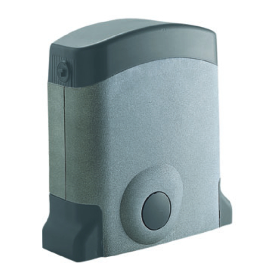
Posibilidad de uso • Los equipos detallados en este manual de instrucciones se deben destinar El grupo 101/SL402409 mueve cancelas correderas de hasta 400kg. únicamente al uso para el cual han sido expresamente concebidos: "La motorización de puertas y cancelas". El uso de los productos y su destino Descripción técnica... -
Page 39: Pruebas Previas Al Montaje
5) Es buena regla señalar la automatización mediante las En caso de avería o funcionamiento incorrecto, desconectar la alimentación ¡CUIDADO! placas de advertencia (similares a la de la fi gura) que eléctrica antes del equipo y contactar con el servicio de asistencia técnica. APERTURA AUTOMATICA debe estar fácilmente visible. -
Page 40: Desbloqueo
Montaje de la cremallera DESBLOQUEO • Para fi jar la cremallera en la cancela corredera hace falta actuar como está indicado a continuación: La operación de desbloqueo generalmente se debe hacer con el motor parado - Desbloquear el motorreductor (fi g.11), apoyar el primer elemento de la a falta de energía eléctrica. -
Page 41: Programador Electrónico
Comprobar que al activar los dispositivos de seguridad se apaguen los PILO- PROGRAMADOR ELECTRONICO TOS acoplados a éstos. Programador para motor en corriente continua con receptor incorporado, que En caso de que el PILOTO rojo de alimentación no se encienda, comprobar permite la memorización de 300 códigos para el usuario (ver "Mando vía las condiciones de los fusibles y la conexión del cable de alimentación entre radio", en pág. -
Page 42: Indicaciones En El Display
INDICACIONES EN EL DISPLAY D1 PROCEDIMIENTO PARA LA PROGRAMACION A) Programación del programador alarmas para ambos topes mecánicos activados al mismo tiempo Antes de empezar, comprobar que la puerta está cerrada, el display luminoso está apagado y los error en los parámetros almacenados en la memoria pilotos L4, L5, L7 y L8 están todos encendidos. -
Page 43: Mando Vía Radio
B) Programación del tiempo de deceleración Presionando por primera vez la tecla "PROG" en el display comparece La pulsación de la tecla "PROG" desde el punto detallado en la fi gura 8 el símbolo y empieza la programación del tiempo de apertura, que se lleva a la fase de programación del tiempo de deceleración. -
Page 44: Modalidad De Funcionamiento
A - Almacenamiento de un canal (fi g. 12) CONEXION DE LA ANTENA PARA MODULO RF DE 433MHz 1. Presionar el boton "P3" MEMO y mantenendo pulsado: el PILOTO El receptor está dotado de antena propia, que consta de un trozo de hilo "L2"... -
Page 45: Cargador De Baterías (Opcional)
• La autonomía del sistema cuando está alimentado por la batería está CARGADOR DE BATERIAS (OPCIONAL) estrictamente ligada a las condiciones ambientales y a la carga conectada en la salida de 24V de la central (que sigue estando alimentada incluso Este dispositivo permite el funcionamiento del grupo motorreductor para a falta de fl... -
Page 46: Caratteristiche Tecniche
- Nombre de fonctions disponibles Nbre - Número de funciones gobernables N° - Nombre de codes mémorisables (S449) Nbre - Número de códigos almacenables (S449) N° By CARDIN ELETTRONICA spa Via Raffaello, 36 31020 San Vendemiano (TV) Italy Tel: +39/0438.401818 Fax: +39/0438.401831 email (Italy): Sales.offi...
Need help?
Do you have a question about the 101/SL402409 and is the answer not in the manual?
Questions and answers