Table of Contents
Advertisement
Available languages
Available languages
Quick Links
CARDIN ELETTRONICA spa
Via del lavoro, 73 - Z.I. Cimavilla
3 1 0 1 3 C o d o g n è ( T V ) I t a l y
Tel:
Fax:
email (Italian): Sales.office.it@cardin.it
email (Europe):
Http:
AUTOMAZIONE INTEGRATE PER CANCELLI A BATTENTE
INTEGRATED AUTOMATION FOR HINGED GATES
AUTOMATISME INTÉGRÉ POUR PORTAILS BATTANTS
INTEGRIERTE DREHTORANTRIEBE
AUTOMATIZACIÓN INTEGRATO PARA CANCILLAS BATIENTES
DEUTSCH
ACHTUNG! Bevor mit der Installation begonnen wird, sollte
die Anleitung aufmerksam gelesen werden!
Anzeigemenü
ESPAÑOL
¡ATENCIÓN! Antes de iniciar la instalación del sistema,
leer atentamente las instrucciones.
BL
+39/0438.404011-401818
+39/0438.401831
24Vdc
Motors
Sales.office@cardin.it
www.cardin.it
Seite
28
29
Seite
29
29
Seite
30
Seite
31
Seite
32
Seite
33
33
Seite
34
Seite
34-35
Seite
48
Página
36
37
Página
37
37
Página
39
Página
40
Página
41
41
Página
42
Página
42-43
Página
48
Series
Instruction manual
ZVL513.00
BLi824
Questo prodotto è stato testato e collaudato nei laboratori della casa costruttrice, la quale ne ha verificato la
perfetta corrispondenza delle caratteristiche con quelle richieste dalla normativa vigente. This product has been
tried and tested in the manufacturer's laboratory who have verified that the product conforms in every aspect to
the safety standards in force. Ce produit a été testé et essayé dans les laboratoires du fabriquant. Pour l'installer
suivre attentivement les instructions fournies. Dieses Produkt wurde in den Werkstätten der Herstellerfirma
auf die perfekte Übereinstimmung ihrer Eigenschaften mit den von den geltenden Normen vorgeschriebenen
getestet und geprüft. Este producto ha sido probado y ensayado en los laboratorios del fabricante, que ha
comprobado la perfecta correspondencia de sus características con las contempladas por la normativa vigente.
24VDC MOTORS 205/BLi824
ITALIANO
ATTENZIONE! Prima di iniziare l'installazione leggere le
istruzioni attentamente!
ENGLISH
ATTENTION! Before installing this device read the
following instructions carefully!
FRANÇAIS
ATTENTION! Avant de commencer la pose, lire
attentivement les instructions!
Consignes importants
Model
Date
-
11-01-2011
Pagina
4
5
Pagina
5
5
6
Pagina
7
Pagina
8
Pagina
9
9
Pagina
10
Pagina
10-11
Pagina
48
Page
12
13
Page
13
13
14
Page
15
Page
16
Page
17
17
Page
18
Page
18-19
Page
48
Page
20
21
Page
21
21
22
Page
23
Page
24
Page
25
25
Page
26
Page
26-27
Page
48
Advertisement
Table of Contents

Related Manuals for Cardin Elettronica 205/BLi824


Summary of Contents for Cardin Elettronica 205/BLi824
-
Page 1: Table Of Contents
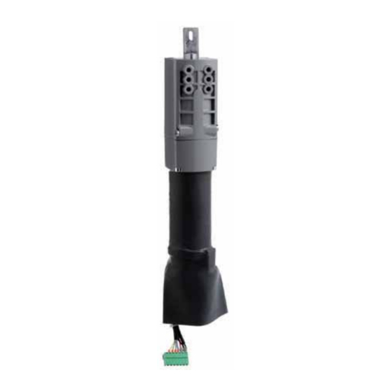
AUTOMAZIONE INTEGRATE PER CANCELLI A BATTENTE INTEGRATED AUTOMATION FOR HINGED GATES AUTOMATISME INTÉGRÉ POUR PORTAILS BATTANTS INTEGRIERTE DREHTORANTRIEBE AUTOMATIZACIÓN INTEGRATO PARA CANCILLAS BATIENTES 24VDC MOTORS 205/BLi824 ITALIANO ATTENZIONE! Prima di iniziare l'installazione leggere le istruzioni attentamente! Avvertenze importanti Pagina Istruzione per l’utilizzo... - Page 2 ESEMPIO D'INSTALLAZIONE - INSTALLATION EXAMPLE - EXEMPLE D'INSTALLATION - ANLAGENART - INSTALACIÓN ESTÁNDAR LEGENDA 1 Motoriduttore 2 Fotocellule interne 3 Fotocellule esterne 4 Fotocellule laterali di protezione (FTCS) 5 Programmatore elettronico 6 Lampeggiatore 7 Antenna esterna 8 Selettore a chiave 9 Elettroserratura Attenzione: Lo schema rappresentato è...
- Page 3 SCHEMA ELETTRICO IMPIANTO TIPO - STANDARD WIRING DIAGRAM - SCHÉMA ÉLECTRIQUE DE L'EXEMPLE D'INSTALLATION ELEKTRISCHER SCHALTPLAN ANLAGENART - ESQUEMA ELÉCTRICO INSTALACIÓN ESTÁNDAR CC242EINT ANS400 CS1283 DI 0441 Collegamento motori/encoder a 4 fili Connecting motor/4-wire encoder Branchement moeteur/encoder à 4 fils Anschluss der Motor/encoder mit 4 Drähten CSER Conexionado motor/encoder con 4 conductores...
-
Page 4: Avvertenze Importanti
ESSERE IMPIEGATI SOLO SU STRUTTURE METALLICHE OPPORTUNA- bili. Qualora l’automazione sia adibita al solo passaggio di veicoli MENTE PREDISPOSTE. LA CARDIN ELETTRONICA NON GARANTISCE I dovranno essere poste due targhe di avvertenza di divieto di transito PRODOTTI CHE SONO STATI INSTALLATI IN MANIERA NON CONFORME pedonale (una all’interno, una all’esterno). -
Page 5: Istruzione Per L'utilizzo Pagine
ISTRUZIONI PER L'UTILIZZO AVVERTENZE IMPORTANTI • Il dispositivo è stato realizzato per essere integrato su strutture di cancelli a battente Attenzione! In nessun punto della scheda del programmatore è presente predisposte a riceverlo. Il propulsore (motoriduttore) è dotato di attacchi a vite che la tensione a 230 Vac: si ha solamente la bassissima tensione di sicu- ne consentono il fissaggio all'interno di profili metallici. -
Page 6: Schema Elettrico Pagine
Collegamenti morsettiera Nota La somma delle due uscite per carichi esterni non deve superare 10W. CMN comune per tutti gli ingressi/uscite Nota Il jumper "J6" seleziona il tipo di costa sensibile collegato al morsetto 24: ELS uscita per elettroserratura (pilotata in continua) 12 Vdc – 15 W - in posizione 1 si seleziona la costa con contatto NC;... -
Page 7: Procedura Di Programmazione
PROCEDURA DI PROGRAMMAZIONE (Impostazioni del programmatore e del sensore di corrente) • È obbligatoria la presenza delle battute di apertura e chiusura per entrambe le ante. • Accertarsi che le sicurezze siano a riposo e che la scheda sia alimentata da rete: in caso contrario non si entra in programmazione. •... -
Page 8: Menu Di Visualizzazione
MENU DI VISUALIZZAZIONE Agendo sul tasto PROG si accede in sequenza alle seguenti funzioni: - regolazione del sensore di corrente; - selezione del tipo di motore; - memorizzazione dello stato dei dip-switch; - visualizzazione dello stato dei comandi e delle sicurezze; - impostazione funzione richiusura con ostacolo. -
Page 9: Comando Via Radio
4. Premere il tasto di canale precedentemente scelto sul trasmettitore da memoriz- COMANDO VIA RADIO zare; ad avvenuta memorizzazione il ricevitore emetterà 2 "bip" di mezzo secondo, dopodiché il ricevitore sarà pronto a memorizzare un altro codice. È possibile azionare a distanza l'automazione tramite radiocomando; per configurare 5. -
Page 10: Funzionamento A Batteria
FUNZIONAMENTO A BATTERIA INDICAZIONI DEL DISPLAY Il dispositivo permette il funzionamento del propulsore anche in assenza di rete. VISUALIZZAZIONI ALL’ACCENSIONE Il programmatore integra un circuito di carica per batterie NiMH a 24V gestito da un microcontrollore dedicato, che regola la tensione in relazione allo stato della batteria. Visualizzato per 2 secondi: CC242C = modello della centralina Per evitare il rischio di surriscaldamento utilizzare soltanto batterie fornite dal costruttore (codice ricambio 999540). - Page 11 SEGNALAZIONI DI FUNZIONAMENTO Programmazione del tempo di pausa Programmazione automatica in corso ln programmazione indica che il sistema si è impostato per il funzionamento a singola anta Comunicazione seriale (CSER) attivata (solo per diagnostica) Fase di apertura Blocco Pausa per la richiusura automatica (solo se abilitata) Fase di chiusura Aggiornamento del sensore di corrente anta 1 (in programmazione) Aggiornamento del sensore di corrente anta 2 (in programmazione)
-
Page 12: Important Remarks
IMPORTANT REMARKS IMPORTANT REMARKS IMPORTANT REMARKS READ THE FOLLOWING REMARKS CAREFULLY BEFORE PROCEEDING WITH THE INSTALLATION. PAY PARTICULAR ATTENTION TO ALL THE PARAGRAPHS MARKED WITH THE SYMBOL . NOT READING THESE IMPORTANT INSTRUCTIONS COULD COMPROMISE THE CORRECT WORKING ORDER OF THE SYSTEM AND CREATE DANGER SITUATIONS FOR THE USERS OF THE SYSTEM. -
Page 13: Instructions For Use Pages
IMPORTANT REMARKS INSTRUCTIONS FOR USE Attention! There is no 230 Vac contact on any part of the electronic card: • This device has been created to be integrated into the structure of specially made only low voltage safety current is available. In conformity with the electrical hinged gates. -
Page 14: Wiring Diagram Pages
Terminal board connections Note The total of the 2 external device outputs must not exceed 10 W. CMN common for all inputs and outputs. Note Jumper "J6" identifies the type of safety edge connected to binding post 24: ELS electric lock output (fed continuously) 12 Vdc - 15 W. - in position 1 the safety edge with NC contact is selected;... -
Page 15: Programming Procedure
PROGRAMMING PROCEDURE (Setting the programmer and the current sensor) • The installation of both anti-derailment buffers is absolutely obligatory before starting programming. • Make sure the safety devices are at rest and the ECU is receiving mains power otherwise you will not be able to enter programming. •... -
Page 16: Display Mode
DISPLAY MENU Using the PROG button you can access the following functions in sequence: - set the current sensor level; - memorising the status of the dip-switches; - selecting the type of motor; - display the status of the command and safety devices; - reclosure after encountering an obstacle;... -
Page 17: Remote Control
4. Press the previously chosen channel buttons on the transmitter which you wish to REMOTE CONTROL memorise; the receiver will sound 2 "beeps" of half a second each after which the receiver will be ready to receive another code. The system can be remotely activated using radio control devices; to set the two 5. -
Page 18: Battery Powered Operation
BATTERY POWERED OPERATION INDICATIONS ON THE DISPLAY This device allows the propulsion unit to work during blackouts. START UP DISPLAY • The programmer has a built in charger for NiMH 24V batteries that is managed by a dedicated micro controller. The control chip adjusts the voltage according to the condition of the batteries. - Page 19 Operational indications Pause time programming Automatic programming under way During programming this means that the system is set to single gate leaf operation Serial line (CSER) active (only for diagnostics) Opening stage Block Pause for automatic reclosing (if activated) Closing stage Current sensor updating for gate leaf 1 (only during programming) Current sensor updating for gate leaf 2 (only during programming) Current sensor updating for gate leaf 1 + 2 (only during programming)
- Page 20 POUR ÊTRE UTILISÉS EXCLUSIVEMENT SUR STRUCTURES MÉTALLIQUES vue. Dans l’hypothèse où l’automatisme serait affecté exclusivement EXPRESSÉMENT PRÉVUES À CET EFFET. CARDIN ELETTRONICA NE DONNE au passage de véhicules, il faudra prévoir deux panneaux d’interdic- AUCUNE GARANTIE POUR DES PRODUITS QUI NE SONT PAS INSTALLÉS tion de passage aux piétons (l’un à...
-
Page 21: Instructions Pour L'utilisation
CONSIGNES IMPORTANTES! INSTRUCTIONS POUR L’UTILISATION Attention! En aucun point de la carte du programmateur il y a une tension • Le dispositif a été conçu de manière à pouvoir être intégré sur structures de portails de 230 Vac mais uniquement de la très basse tension de sécurité. battants prévues à... -
Page 22: Schéma Électrique Pages
Branchements du bornier Nota Le cavalier "J6" permet de sélectionner le type de bord de sécurité branché à la borne 24: CMN commun pour toutes les entrées/sorties - en position 1, sélection du bord de sécurité avec contact N.F., ELS sortie pour serrure électrique (pilotée en continu) 12 Vdc – 15 W - en position 2, sélection du bord de sécurité... -
Page 23: Procédé De Programmation
PROCÉDÉ DE PROGRAMMATION (configurations du programmateur et du senseur de courant) • Il est obligatoire d’installer les fins de course en ouverture et fermeture pour les deux vantaux. • Contrôler que les dispositifs de sécurité soient en veille et que la carte soit alimentée par le réseau d’alimentation; en cas contraire, il est impossible d’entrer en programmation. -
Page 24: Menu De Visualisation
MENU DE VISUALISATIONS La touche PROG permet d’accéder en séquence aux fonctions suivantes: - programmation du niveau du senseur de courant; - mémorisation du réglage des dip-switches; - sélection du type de moteur; - visualisation de l’état des commandes et des dispositifs de sécurité; - programmation du fonction de refermeture avec obstacle interposé. -
Page 25: Commande Via Radio
4. Appuyer sur la touche de canal choisie précédemment sur l'émetteur à mémoriser. Le COMMANDE PAR RADIO récepteur signalera que la mémorisation a eu lieu en émettant 2 bips d'une demi-seconde. Après quoi, le récepteur sera prêt à mémoriser un autre code. Il est possible d’actionner à... -
Page 26: Fonctionnement À Batterie
INDICATIONS SUR L’AFFICHEUR FONCTIONNEMENT À BATTERIE Le dispositif permet le fonctionnement du groupe propulseur même en cas de coupure VISUALISATIONS À L’ALLUMAGE de courant. Le programmateur intègre un circuit de charge pour batteries NiMH à 24V géré par un visualisé pendant 2 secondes: “CC242C" = modèle de la centrale micro-contrôleur dédié... - Page 27 Signalisations de fonctionnement Programmation du temps de pause Programmation automatique en cours Indique en phase de programmation que le système s’est positionné pour un fonctionnement à un seul vantail Communication sérielle (CSER) activée (seulement pour diagnostique) Phase d’ouverture Blocage Pause avant la refermeture automatique (seulement si validée) Phase de fermeture Actualisation du senseur de courant vantail 1 (en programmation) Actualisation du senseur de courant vantail 2 (en programmation)
-
Page 28: Wichtige Hinweise
WICHTIGE HINWEISE WICHTIGE HINWEISE WICHTIGE HINWEISE VOR DER INSTALLATION SOLLTEN DIE NACHSTEHENDEN HINWEISE AUFMERKSAM GELESEN UND FÜR SPÄTERE VERWENDUNG AUFBEWAHRT WERDEN. BESONDERE AUFMERKSAMKEIT SOLLTE ALLEN IM TEXT BEFINDLICHEN HINWEISEN GESCHENKT WERDEN. DEREN NICHT- BEACHTUNG KÖNNTE DEN ORDENTLICHEN BETRIEB DES SYSTEMS BEEINTRÄCHTIGEN. Abbildung angezeigt) kenntlich zu machen. -
Page 29: Betriebsanleitungen Seiten
BETRIEBSANLEITUNG WICHTIGE HINWEISE Achtung! An keiner Stelle auf der Leiterplatte der Steuerung befindet • Die Vorrichtung wurde entwickelt, um in Drehflügeltore integriert zu werden, die für sich die Stromspannung von 230 Vac: es ist allein nur die sehr niedrige ihre Aufnahme vorgerüstet sind. Der Antrieb (Getriebemotor) ist mit Schrauban- Sicherheitsspannung vorhanden. -
Page 30: Elektrischer Schaltplan
Anschlussklemmleisten-Anschlüsse Anmerkung Der Jumper "J6" wählt den Typ der an Klemme 24 angeschlossenen Sicherheitsleiste aus: CMN Neutralleitung für alle Eingänge/Ausgänge - In Position 1 wird die Leiste mit NC-Kontakt ausgewählt; ELS Ausgang für Elektroschloss (ununterbrochen gesteuert) 12 Vdc – 15 W 9-10 LC-CH2 Ausgang (stromfreier Kontakt N.O.) für Aktivierung des Wachlichtes - In Position 2 wird die Sicherheitsleiste mit Kontakt 8.2 kΩ... -
Page 31: Programmierverfahren
PROGRAMMIERVERFAHREN (Einstellungen der Steuerung und des Strommess-Sensors) • Das Vorhandensein der Öffnungs- und Schließungsanschläge ist für beide Torflügel obligatorisch. • Sich vergewissern, dass die Sicherheitsvorrichtungen sich in Ruhestellung befinden und dass die elektronische Leiterplatte mit Netzstrom versorgt wird; andernfalls ist der Eintritt in die Programmierung nicht möglich. •... - Page 32 MENU DER ANZEIGE - Einstellung des Raumes für die begrenzte Öffnung; Durch Betätigung der Taste PROG erfolgt der Zugriff zu den folgenden Funktionen: - Einstellung der Stromsensorstufe; - Speicherung des Zustands der Dip-Schalter; - Motorentypwahl; - Anzeige des Zustands der Steuerungen und der Sicherheiten; - Einstellung der Schließfunktion bei einem Hindernis.
-
Page 33: Funkbefehl
5. Um den Modus zu beenden, 3 Sekunden ohne einen Code zu speichern verstreichen FERNBEDIENUNG lassen. Der Empfänger gibt einen 5 Sekunden dauernden "Bip"-Ton von sich und verlässt die Modalität. Die Automatisierung kann mittels einer Funkfernsteuerung ferngesteuert werden; zur Hinweis: Wenn der Speicher voll ist, gibt der Summer zehn, schnell aufeinanderfolgende Konfiguration der zwei Funktionen auf den Kanälen A-B-C-D werden die Wahl-Jumper Biptöne von sich und beendet automatisch den "funkgesteuerten"... -
Page 34: Batteriebetrieb
BATTERIEBETRIEB DISPLAY-ANZEIGEN Die Vorrichtung gestattet den Betrieb der Antriebsgruppe auch bei Ausfall der Netz- ANZEIGEN BEIM ANSCHALTEN stromversorgung. Die Steuerung verfügt über einen Batterieladeschaltkreis für NiMH- 24V-Batterien, der von einem dafür vorgesehenen Mikro-Kontroller zur vom Batteriezu- stand abhängigen Spannungsregelung verwaltet wird. Anzeige für zwei Sekunden: CC242C = Steuereinheitsmodell Zur Vermeidung der Überhitzungsgefahr sollten nur die vom Hersteller gelieferten Batterien (Ersatzteilnummer 999540) verwendet werden. - Page 35 BETRIEBSFUNKTIONSMELDUNGEN Programmierung der Pausenzeit Automatische Programmierung im Gange Zeigt bei der Programmierung an, dass das System sich auf die Betriebsweise mit einem einzelnen Torflügel eingestellt hat Serielle Verbindung (CSER) aktiviert (nur für Diagnose) Öffnungsphase Blockierung Pause für die automatische Wiederschließung (nur wenn freigegeben) Schließungsphase Aktualisierung des Stromsensors des Torflügels 1 (in Vorbereitung) Aktualisierung des Stromsensors des Torflügels 2 (in Vorbereitung)
-
Page 36: Advertencias Importantes
TRUIDOS PARA UTILIZARSE SOLAMENTE EN ESTRUCTURAS METÁ- Si la automatización está destinada únicamente al paso de vehículos LICAS OPORTUNAMENTE PREPARADAS. CARDIN ELETTRONICA NO se tienen que poner dos placas de advertencia de prohibición de paso GARANTIZA LOS PRODUCTOS CUYA INSTALACIÓN NO ES CONFORME peatonal (una al interior y otra al exterior). -
Page 37: Instrucciones Para El Usuario Páginas
INSTRUCCIONES PARA EL USO ADVERTENCIAS IMPORTANTES • El dispositivo ha sido realizado para incorporarlo en estructuras de cancillas de ¡Atención! En ningún punto de la tarjeta del programador está presente la batiente predispuestas para recibirlo. El propulsor (motorreductor) está provisto tensión de 230 Vac: se dispone sólo de la muy baja tensión de seguridad. - Page 38 Conexionado placa de bornes Nota la suma de las 2 salidas para cargas exteriores no debe exceder de 10W. Nota El puente "J6" selecciona el tipo de banda sensible conectada con el borne 24: CMN Común para todas las entradas/salidas - en posición 1 se selecciona la banda sensible con contacto NC;...
-
Page 39: Procedimiento De Programación
PROCEDIMIENTO DE PROGRAMACIÓN (FIJACIÓN ENTRADAS PROGRAMADOR Y SENSOR DE CORRIENTE) • Es obligatoria la presencia de los topes de apertura y cierre para las dos hojas. • Controlar que los dispositivos de seguridad se encuentren en la posición de reposo y que la tarjeta esté alimentada por la red eléctrica;... -
Page 40: Menú De Visualización
MENÚ DE VISUALIZACIÓN - configuración del nivel del sensor de corriente; Actuando sobre la tecla PROG, se accede -en secuencia- a las siguientes funciones: - selección del tipo de motor; - memorización del estado de los dip-switches; - configuración función de cierre con obstáculo; - visualización del estado de los dispositivos de mando y seguridad;... -
Page 41: Mando Vía Radio
4. Presionar la tecla de canal seleccionada con anterioridad en el emisor a memorizar; MANDO VÍA RADIO realizada la memorización, el receptor emitirá 2 "Toques" de medio segundo, después de lo cual estará listo para memorizar otro código. Es posible accionar a distancia la automatización por medio del radiomando; para confi- 5. -
Page 42: Funcionamiento Por Batería
FUNCIONAMIENTO POR BATERÍA INDICACIONES EN EL DISPLAY El dispositivo permite el funcionamiento del grupo incluso en ausencia de red. VISUALIZACIONES TRAS EL ENCENDIDO El programador incorpora un circuito de carga para baterías NiMH de 24V gobernado por un micro controlador dedicado que regula la tensión en función del estado de la batería. Visualizado por dos segundos: CC242C = modelo de la centralita Para evitar el riesgo de recalentamiento, utilizar sólo baterías que hayan... - Page 43 SEÑALIZACIONES DE FUNCIONAMIENTO Programación del tiempo de pausa Programación automática en curso En la modalidad “programación” indica que el sistema ha sido seleccionado para el funcionamiento con una sola hoja Comunicación serie (CSER) activada (solamente para diagnóstico) Fase de apertura Bloqueo Pausa para el cierre automático (sólo si ha sido habilitada) Fase de cierre...
- Page 44 NOTES...
- Page 45 NOTES...
- Page 46 NOTES...
- Page 47 Sales.office.it@cardin.it email (Europe): Sales.office@cardin.it (Direttiva Macchine 89/392/CEE, All. II) Http: www.cardin.it CARDIN ELETTRONICA S.p.A. Il costruttore: DICHIARA CHE L'APPARECCHIATURA DESTINATA AD ESSERE INSERITA IN MACCHINE E NON FUNZIONANTE IN MODO INDIPENDENTE: Nome dell'apparato Motoriduttore BLi824 - BLi924 - BLi924ESB Tipo di apparato...
-
Page 48: Technische Eigenschaften
CARATTERISTICHE TECNICHE DIMENSIONI D'INGOMBRO - EXTERNAL DIMENSIONS DIMENSIONS D'ENCOMBREMENT Specifiche tecniche dell'attuatore Alimentazione AUSSENABMESSUNGEN - DIMENSIONES MÁXIMAS Assorbimento Potenza assorbita Ciclo di lavoro 4 fori filettati M8 Velocità riduttore giri/min 1,27 4 threaded holes M8 Coppia 4 trous fileté M8 Grado di protezione 4 Gewindebohrung M8 4 agujeros roscados M8...
Need help?
Do you have a question about the 205/BLi824 and is the answer not in the manual?
Questions and answers