Table of Contents
Advertisement
Available languages
Available languages
Quick Links
CARDIN ELETTRONICA spa
Via Raffaello, 36
31020 San Vendemiano (TV) Italy
Tel:
Fax:
email (Italian): Sales.office.it@cardin.it
email (Europe): Sales.office@cardin.it
Http:
AUTOMAZIONE INTERRATA PER CANCELLI A BATTENTE CON MOTORE IN CORRENTE CONTINUA
UNDERGROUND AUTOMATION FOR HINGED GATES WITH A DC POWERED MOTOR
AUTOMATISME ENTERRE POUR PORTAILS BATTANTS AVEC MOTEUR À COURANT CONTINU
UNTERFLUR-DREHTORANTRIEBE MIT GLEICHSTROMMOTOR
AUTOMATIZACION ENTERRADA PARA CANCILLAS BATIENTES CON MOTOR DE CORRIENTE CONTINUA
ITALIANO
ATTENZIONE! Prima di iniziare l'installazione leggere
le istruzioni attentamente!
Impianto tipo
ENGLISH
ATTENTION! Before installing this device read the
following instructions carefully!
HL
+39/0438.404011-401818
+39/0438.401831
www.cardin.it
Pagina
3-7
Pagina
Pagina
Pagina
Pagina
10
10-11
Pagina
12
Pagina
13
Pagina
14
14-15
Pagina
15
Pagina
16
Pagina
20
Page
3-7
Page
Page
11
17-18
Page
18
18-19
Page
20
Page
21
Page
22
22-23
Page
23
Page
24
Page
52
Instruction manual
ZVL480.00
Questo prodotto è stato testato e collaudato nei laboratori della casa costruttrice, la quale ne ha verificato la
perfetta corrispondenza delle caratteristiche con quelle richieste dalla normativa vigente. This product has been
tried and tested in the manufacturer's laboratory who have verified that the product conforms in every aspect to
the safety standards in force. Ce produit a été testé et essayé dans les laboratoires du fabriquant. Pour l'installer
24Vdc
suivre attentivement les instructions fournies. Dieses Produkt wurde in den Werkstätten der Herstellerfirma
auf die perfekte Übereinstimmung ihrer Eigenschaften mit den von den geltenden Normen vorgeschriebenen
Motors
getestet und geprüft. Este producto ha sido probado y ensayado en los laboratorios del fabricante, que ha
comprobado la perfecta correspondencia de sus características con las contempladas por la normativa vigente.
24 Vdc Motors
ATTENTION! Avant de commencer la pose, lire atten-
tivement les instructions!
Type d'installation
ACHTUNG! Bevor mit der Installation begonnen wird,
sollte die Anleitung aufmerksam gelesen werden.
2
8
9
9
Anzeigemenü
¡ATENCIÓN! Antes de iniciar la instalación del sistema,
leer atentamente las instrucciones.
2
8
1
Series
Model
HL
2524ESB-1824ESB 13-09-2005
800/HL2524ESB
800/HL1824ESB
FRANÇAIS
Page
Page
Page
Page
Page
Page
Page
Page
Page
Page
DEUTSCH
Seite
Seite
Seite
Seite
Seite
Seite
Seite
Seite
Seite
Seite
Seite
ESPAÑOL
Página
Página
Página
Página
Página
Página
Página
Página
Página
Página
Date
2
3-7
8
25
25-26
26
26-27
28
29
30
30-31
31
32
52
2
3-7
8
33
33-34
34
34-35
36
37
38
38-39
39
40
52
2
3-7
8
41
41-42
42
42-43
44
45
46
46-47
47
48
52
Advertisement
Table of Contents

Related Manuals for Cardin Elettronica 800/HL2524ESB


Summary of Contents for Cardin Elettronica 800/HL2524ESB
-
Page 1: Table Of Contents
CARDIN ELETTRONICA spa Series Date Instruction manual Model Via Raffaello, 36 ZVL480.00 2524ESB-1824ESB 13-09-2005 31020 San Vendemiano (TV) Italy Questo prodotto è stato testato e collaudato nei laboratori della casa costruttrice, la quale ne ha verificato la Tel: +39/0438.404011-401818 perfetta corrispondenza delle caratteristiche con quelle richieste dalla normativa vigente. This product has been tried and tested in the manufacturer's laboratory who have verified that the product conforms in every aspect to... -
Page 2: Installation Example
ESEMPIO D'INSTALLAZIONE - INSTALLATION EXAMPLE - EXEMPLE D'INSTALLATION - ANLAGENART - INSTALACIÓN ESTÁNDAR LEGENDA 1 Motoriduttore (SX) 2 Motoriduttore (DX) - 5 0 3 Fotocellula interna 4 Fotocellula esterna 5 Lampeggiatore 6 Selettore a chiave 7 Elettroserratura 8 Antenna esterna (Cavo coassiale RG58 Impedenza 50 ) 9 Interruttore onnipolare con apertura contatti min. -
Page 3: Schemi Di Montaggio Pagine
MONTAGESCHEMA GETRIEBEMOTOR - ESQUEMA DE MONTAJE MOTORREDUCTOR 800/HL2524ESB AT T E N Z I O N E ! - AT T E N T I O N ! - AT T E N T I O N ! - A C H T U N G ! - ¡ C U I D A D O ! Prima di collocare la cassetta all'interno dello scavo e di avvolgerla di calcestruzzo inserire le 6 viti "E"... - Page 4 SCHEMA DI MONTAGGIO MOTORIDUTTORE - GEARED MOTOR ASSEMBLY - SCHÉMA DE MONTAGE DU MOTORÉDUCTOR MONTAGESCHEMA GETRIEBEMOTOR - ESQUEMA DE MONTAJE MOTORREDUCTOR 800/HL1824ESB AT T E N Z I O N E ! - AT T E N T I O N ! - AT T E N T I O N ! - A C H T U N G ! - ¡ C U I D A D O ! Prima di collocare la cassetta all'interno dello scavo e di avvolgerla di calcestruzzo inserire le 6 viti "E"...
- Page 5 DIMENSIONI D’INGOMBRO - EXTERNAL DIMENSIONS - DIMENSIONS D’ENCOMBREMENT AUSSENABMESSUNGEN - DIMENSIONES MAXIMAS LIMITI D’IMPIEGO - LIMITS OF USE - CONTRAINTES D'UTILISATION - ANWENDUNGSGRENZEN - LIMITES DE EMPLEO...
- Page 6 ESEMPIO D’INSTALLAZIONE - INSTALLATION EXAMPLE - EXEMPLE D'INSTALLATION INSTALLATIONS BEISPEIL - EJEMPLO DE INSTALACION 64mm...
- Page 7 MONTAGGIO DISPOSITIVO 180° - ASSEMBLING THE 180° DEVICE - MONTAGE DU DISPOSITIF 180° MONTAGE VORRICHTUNG 180° - MONTAJE DISPOSITIVO 180° Pos. 0 Pos. 180 REGOLAZIONE FINECORSA MECCANICI - ADJUSTING THE MECHANICAL TRAVEL LIMITS - RÉGLAGE DES FINS DE COURSE MÉCANIQUES - EINSTELLUNG DES MECHANISCHEN ENDANSCHLAGES - REGULACION TOPES MECANICOS SBLOCCO MANUALE - MANUAL RELEASE MECHANISM - DÉVERROUILLAGE MANUEL MANUELLE ENTRIEGELUNG - DESBLOQUEO MANUAL...
-
Page 8: Schema Elettrico (Impianto Tipo)
SCHEMA ELETTRICO IMPIANTO TIPO - STANDARD WIRING DIAGRAM - SCHÉMA ÉLECTRIQUE DE L'EXEMPLE D'INSTALLATION - ELEKTRISCHER SCHALTPLAN ANLAGENART - ESQUEMA ELECTRICO INSTALACION ESTÁNDAR CC242ESBBS CC242ESBBS ANS400 CS 1218 DI0355 Collegamento motori/encoder a 4 fili Connecting motor/4-wire encoder Branchement moeteur/encoder à 4 fils Anschluss der Motor/encoder mit 4 Drähten CSER Conexionado motor/encoder con 4 conductores... -
Page 9: Avvertenze Importanti
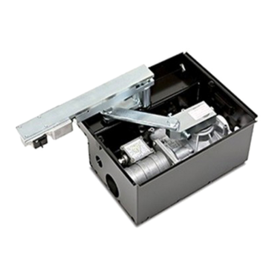
PROCEDURA DI MONTAGGIO DESCRIZIONE TECNICA perno d'incernieramento del cancello rispetto al pilastro e al tipo di apertura 800/HL2524ESB Motoriduttore autobloccante, apertura anta max 110°. (90°-110°-180°) da realizzare (fig. 5). 806/HLCF1Z Cassa di fondazione in acciaio zincato con leve per apertura anta I", fig. -
Page 10: Sblocco Manuale
REGOLAZIONE FINE CORSA MECCANICO 15 "Verifica delle batterie"). (solo per mod. 800/HL2524ESB con cassa 806/HLCF1 - fig. 8) Il programmatore ha la facoltà di attivare automaticamente il motore quando Il finecorsa meccanico regolabile previsto tra la leva "N" del motoriduttore e la sporgenza... - Page 11 Collegamenti morsettiera Massa antenna ricevitore radio Nota La somma delle due uscite per carichi esterni non deve superare 10W. CMN comune per tutti gli ingressi/uscite ELS uscita per elettroserratura (pilotata in continua) 12 Vdc – 15 W TUTTI I CONTATTI N.C. NON UTILIZZATI VANNO PONTICELLATI e di 9-10 LC-CH2 uscita (contatto puro, N.A.) per attivazione luce di cortesia conseguenza i test sulle sicurezze corrispondenti (FTCI, FTCS –...
-
Page 12: Procedura Di Programmazione
PROCEDURA DI PROGRAMMAZIONE (Impostazioni del programmatore e del sensore di corrente) È obbligatoria la presenza delle battute di apertura e chiusura per entrambe le ante. Elettroserratura (DIP 10) Attenzione: Se sul display compare il simbolo trascorsi 3 minuti Dip 10 “ON” = Elettroserratura abilitata 1 2 3 4 5 6 7 8 9 10 da quando è... -
Page 13: Menu Di Visualizzazione
Riposizionamento automatico in modo da recuperare la posizione. A questo punto il programmatore riprende Se si dovesse verificare un blocco del programmatore dovuto ad un’anomalia del il normale funzionamento. Per eseguire il riposizionamento automatico senza conteggio encoder , ad un reset del programmatore , allo sblocco attendere i 3 minuti, è... -
Page 14: Comando Via Radio
Nota: Quando la memoria del ricevitore è prossima al completamento, la ricerca COMANDO VIA RADIO (figura 10 - pagina 8) dell’utente può durare un massimo di 1 secondo da quando è stato ricevuto il comando radio. Se il Led "L4" è sempre acceso, la memoria è interamente È... -
Page 15: Funzionamento A Batteria
4) Manovra di emergenza LED di segnalazione (vedi pag. 8) Nel caso in cui il programmatore elettronico non dovesse più rispondere ai comandi per un malfunzionamento, agire sugli ingressi EMRG1 o EMRG2 per muovere L2: acceso quando la corrente erogata dal circuito di carica-batterie è superiore alla anta 1 in modalità... -
Page 16: Indicazioni Del Display
Segnalazioni di funzionamento INDICAZIONI DEL DISPLAY (D1 - pagina 8) Visualizzazioni all’accensione Programmazione del tempo di pausa Visualizzato per due secondi: "CC242E" = modello della centralina Programmazione automatica in corso segnala la memorizzazione della configurazione dei dip-switch e la versione del firmware. Durante la programmazione indica che il sistema si è... -
Page 17: Important Remarks Page
This product and all its relative components has been designed and manufac- spare parts. The appliance is not suitable for continuous operation and must be tured by Cardin Elettronica who have verified that the product conforms in every adjusted according to the model (see technical data on page 52). -
Page 18: Manual Release Mechanism
MECHANICAL TRAVEL LIMIT ADJUSTMENT The programmer can activate the motor automatically. This is indicated (only for mod. 800/HL2524ESB with embedding case 806/HLCF1- fig. 8) by the warning lights pre-flashing for 10 seconds, and by the symbol The adjustable travel limit placed between the lever "N" of the geared motor and the appearing on the display. - Page 19 Terminal board connections Outer conductor for radio receiver antenna CMN common for all inputs and outputs. Note The total of the 2 external device outputs must not exceed 10 W. ELS electric lock output (fed continuously) 12 Vdc - 15 W. ALL UNUSED NC CONTACTS MUST BE JUMPED and consequently the 9-10 LC-CH2 Potential free contact for the activation of the courtesy light security device test must also be deactivated (FTCI , FTCS - Dip 7 and Dip...
-
Page 20: Caratteristiche Tecniche
PROGRAMMING PROCEDURE (Setting the programmer and the current sensor) absolutely obligatory before starting programming. display menu" (page 21). Electric lock (DIP 10) Caution: If the symbol appears on the display after 3 Dip 10 "ON" = Electric lock enabled 1 2 3 4 5 6 7 8 9 10 minutes has passed since the programmer was powered Dip 10 "OFF"... -
Page 21: Automatic Repositioning
Automatic repositioning To carry out automatic repositioning without waiting for 3 minutes you may send If the programmer blocks due to an encoder count error , after a program- a (TA, TC, TAL or TD) command to the programmer. If a “TA” command is given mer reset , when one of the motors has been released or there is a... -
Page 22: Remote Control
Note: When the memory is almost full the time required to search for a user REMOTE CONTROL (fig. 10 - page 8) code could take up to 1 second from when the command was received. If LED "L4" remains lit memory is completely full. To memorise a new transmit- The system can be remotely activated using radio control devices;... -
Page 23: Battery Powered Operation
4) Emergency manoeuvre If the electronic programmer no longer responds to commands due to a power. malfunction you may use the EMRG1 or EMRG2 inputs to move gate leaf 1 manually. The EMRG1 and EMRG2 inputs directly command the motor Signal LEDs (page 8) relays without passing through the logic control. -
Page 24: Indications On The Display
INDICATIONS ON THE DISPLAY (D1, page 8) Operational indications Start up display Pause time programming Shown for 2 seconds: "CC242E" = ECU model; Automatic programming under way Indicates the dip-switch setting memorisation stage and firmware version During programming this means that the system is set to single gate leaf operation Alarm indications Serial line (CSER) active... -
Page 25: 806/Hlcf1
DESCRIPTION TECHNIQUE - Installer une butée d’arrêt mécanique en fermeture (dét. "1", fig. 5) 800/HL2524ESB Motoréducteur irréversible, ouverture de vantail 110° maxi. 806/HLCF1 Caisson de fondation en acier galvanisé traité par cataphorèse avec - Réaliser un puits bétonné "A" (fig. 6), à l’endroit prédéterminé, en fonction de la leviers pour une ouverture de vantail 110°... -
Page 26: Déverrouillage Manuel
CONSIGNES IMPORTANTES! - Placer le levier du portail "H" sur le pivot du caisson, après avoir graissé ce dernier. Attention! En aucun point de la carte du programmateur il y a une tension Introduire la bille d’articulation "L" dans le levier. de 230 Vac mais uniquement de la très basse tension de sécurité. - Page 27 Branchements du bornier Nota La somme des deux sorties pour dispositifs externes ne doit pas être CMN commun pour toutes les entrées/sorties supérieure à 10 W. ELS sortie pour serrure électrique (pilotée en continu) 12 Vdc – 15 W FAIRE UN PONT SUR TOUS LES CONTACTS N.F. INUTILISÉS et, en consé- 9-10 LC-CH2 sortie (contact non alimenté, N.O.) pour activation de l’éclairage quence, invalider les tests sur les dispositifs de sécurité...
-
Page 28: Procédé De Programmation
PROCÉDÉ DE PROGRAMMATION (configurations du programmateur et du senseur de courant) obligatoire d’installer les fins de course en ouverture et fermeture pour les deux vantaux. est impossible d’entrer en programmation. Décalage en ouverture (DIP 9) Attention: si le symbole apparaît sur l’afficheur 3 minutes Dip 9 “ON”... -
Page 29: Menu De Visualisation
Repositionnement automatique de nouveau normalement. Pour effectuer le repositionnement automatique sans attendre que les 3 Si le programmateur se bloque à cause d’une anomalie de comptage de minutes s’écoulent, il suffit d’envoyer une commande (TA, TC, TAL ou l’encodeur , d’un reset du programmateur , d’un débrayage TD) au programmateur. -
Page 30: Commande Via Radio
Nota: lorsque la mémoire du récepteur est presque saturée, la recherche de l'usager COMMANDE PAR RADIO (fig. 10 - page 8) peut durer au maximum 1 seconde à compter de la réception de la de radio. Si le LED "L4" reste toujours allumé, la mémoire est saturée. Pour pouvoir mémoriser Il est possible d’actionner à... -
Page 31: Fonctionnement À Batterie
4) manœuvre d’urgence Quand les batteries se déchargent complètement (en cas de coupure de courant), le programmateur perd la mémorisation de la position En cas de défaillance du programmateur électronique qui ne répond plus aux occupée par le vantail, donc, une fois que l’alimentation de réseau a commandes, intervenir sur l’entrée EMRG1 ou EMRG2 pour manœuvrer le vantail été... -
Page 32: Indications De L'afficheur
Signalisations de fonctionnement INDICATIONS SUR L’AFFICHEUR (D1, page 8) Visualisations à l’allumage Programmation du temps de pause visualisé pendant deux secondes: “CC242E” = modèle de la centrale Programmation automatique en cours signale la mémorisation de la configuration des dip-switches Indique en phase de programmation que le système et la version du firmware. -
Page 33: Wichtige Hinweise
Seite 52) proportional ist. einstellen und sich an den Vertrieb der Produkte wenden. MONTAGEVERFAHREN TECHNISCHE BESCHREIBUNG 800/HL2524ESB Selbsthemmender Getriebemotor, max. Flügelöffnungswinkel 110°. dungsbolzens gegenüber dem Pfeiler und dem zu erstellenden Öffnungswinkel (90°-110°-180°) wählen (Abb. 5). 806/HLCF1 Versenkbares Grundgehäuse aus verzinktem Stahl mit Kataphoresela- ckierung und Hebeln für maximale Flügelöffnung 110°. -
Page 34: Manuelle Entriegelung
(siehe Seite 39 “Prüfung der Batterien”). EINSTELLUNG DES MECHANISCHEN ENDANSCHLAGES Die Steuerung kann den Motor automatisch aktivieren, wenn auf dem (nur für Mod.800/HL2524ESB mit Gehäuse 806/HLCF1 Abb. 8) Display das Zeichen erscheint; dies wird durch ein Vorblinken von Der vorgesehene einstellbare mechanische Endanschlag zwischen dem Hebel "N" des 10 Sekunden angezeigt. - Page 35 Anschlussklemmleisten-Anschlüsse Anmerkung : Die Summe der beiden Ausgänge für die externen Stromabnehmer darf nicht mehr als 10 W betragen. CMN Neutralleitung für alle Eingänge/Ausgänge ELS Ausgang für Elektroschloss (ununterbrochen gesteuert) 12 Vdc – 15W ALLE NICHT VERWENDETEN N.C.-KONTAKTE MÜSSEN ÜBERBRÜCKT 9-10 LC-CH2 Ausgang (stromfreier Kontakt N.O.) für Aktivierung des Wachlichtes und somit auch die Tests der entsprechenden Sicherheitsvorrichtungen (FTCI, FTCS...
-
Page 36: Programmierverfahren
PROGRAMMIERVERFAHREN (Einstellungen der Steuerung und des Strommess-Sensors) obligatorisch. versorgt wird; andernfalls ist der Eintritt in die Programmierung nicht möglich. Phasenverschiebung bei der Öffnung (DIP 9) Achtung: Wenn auf dem Display das Symbol 3 Minuten Dip 9 “ON” = Phasenverschiebung bei der Öffnung 1 2 3 4 5 6 7 8 9 10 nach dem Einschalten der Stromversorgung für die Steuerung eingeschaltet... - Page 37 Automatische Rückstellung Danach nimmt die Steuerung den normalen Betrieb wieder auf. Zur Ausführung Falls eine Blockierung der Steuerung eintreten sollte, aufgrund einer Ano- der automatischen Rückstellung ohne die 3 Minuten abwarten zu müssen, malie bei der Encoder-Zählung , einer Rückstellung (Reset) der braucht nur ein Befehl (TA, TC, TAL oder TD) an die Steuerung gegeben Steuerung , einer Entriegelung eines der Motoren...
-
Page 38: Funkbefehl
Hinweis: Wenn der Speicher des Empfängers fast voll ist, kann die Suche des FERNBEDIENUNG (Abb. 10 Seite 8) Benutzers maximal 1 Sekunde nach Erhalt der Funksteuerung dauern. Wenn die Led "L4" immer eingeschaltet ist, ist der Speicher vollständig belegt. Um Die Automatisierung kann mittels einer Funkfernsteuerung ferngesteuert werden;... -
Page 39: Batteriebetrieb
3) Manuelle Betätigung mit entriegelten Motoren Achtung!: Falls ein externer Empfänger verwendet werden soll muss dieser, gemäß dem oben Geschilderten, über die Anschlussklemmen 16-17 (Seite 8) Bei entriegelten Motoren können die Torflügel von Hand bewegt werden; bei diesem versorgt werden. Nur so ist es möglich, dass ein über Funk abgegebener Befehl Vorgang kontrolliert die Steuerung nicht die Torflügelpositionen und aus diesem das Tor aktivieren kann. -
Page 40: Displayanzeigen
Betriebsfunktionsmeldungen DISPLAY-ANZEIGEN (D1 - Seite 8) Anzeigen beim Anschalten Programmierung der Pausenzeit Anzeige für zwei Sekunden: "CC242E" = Steuereinheitsmodell Automatische Programmierung im Gange Signalisiert die Speicherung der Konfiguration der Dip-Schalters Zeigt bei der Programmierung an, dass das System sich und der Firmware-Version. auf die Betriebsweise mit einem einzelnen Torflügel eingestellt hat Alarmsignale... -
Page 41: Advertencias Importantes
(intermitencia de trabajo en pág. 52). al distribuidor de los productos. PROCEDIMIENTO DE MONTAJE DESCRIPCION TECNICA 800/HL2524ESB Motorreductor irreversible, apertura hoja máx. 110°. de engoznado de la cancilla respecto al pilar y al tipo de apertura (90°-110°-180°) 806/HLCF1 Caja de cimientos de acero galvanizado con tratamiento con a realizar (fig. -
Page 42: Desbloqueo Manual
- Cerrar la tapa "P" por medio de los dos tornillos suministrados. El programador tiene la posibilidad de activar automáticamente el motor REGULACION DEL TOPE MECANICO (sólo para el mod. 800/HL2524ESB con cuando en el display se visualiza ; esto se señaliza por medio de caja 806/HLCF1 - fig. - Page 43 Conexionado placa de bornes Nota la suma de las 2 salidas para cargas exteriores no debe exceder de 10W. CMN Común para todas las entradas/salidas TODOS LOS CONTACTOS N.C. QUE NO SE UTILICEN DEBEN PUENTEARSE ELS salida para cerradura eléctrica (controlada en continuo) 12 Vdc–15W y, en consecuencia, deben deshabilitarse los test en los dispositivos de seguridad 9-10 LC-CH2 salida (contacto libre de potencial, NA) para activación luz de zona correspondientes (FTCI, FTCS –...
-
Page 44: Procedimiento De Programación
PROCEDIMIENTO DE PROGRAMACIÓN (Fijación entradas programador y sensor de corriente) obligatoria la presencia de los topes de apertura y cierre para las dos hojas. en caso contrario, no se entrará en programación. Cerradura eléctrica (DIP 10) Atención: si en el display se visualiza el símbolo después DIP 10 “ON”... -
Page 45: Menú De Visualización
Reposicionamiento automático este punto, el programador reinicia el funcionamiento corriente. Para realizar el Si se verificara un bloqueo del programador debido a una anomalía de la cuenta reposicionamiento automático sin esperar los 3 minutos, es suficiente enviar un del encoder , tras un reinicio del programador , el desbloqueo de mando de control (TA, TC, TAL o TD) al programador. -
Page 46: Mando Vía Radio
Nota: Cuando la memoria del receptor está a punto de agotarse, la búsqueda del MANDO VÍA RADIO (fig. 10, pág. 8) usuario puede durar 1 segundo como máximo después de recibir el mando radio. Si el LED "L4" está siempre encendido, la memoria está enteramente ocupada. Es posible accionar a distancia la automatización por medio del radiomando;... -
Page 47: Funcionamiento Por Batería
4) Maniobra de emergencia Cuando las baterías se descargan completamente (en ausencia Si el programador electrónico no reaccionara a los controles por un mal fun- de tensión de red), el programador no reconoce la posición de la cionamiento, actuar sobre las entradas EMRG1 o EMRG2 para mover la hoja hoja y, en consecuencia, tras el restablecimiento de la alimentación 1 en modalidad “hombre presente”. -
Page 48: Indicaciones En El Display
INDICACIONES EN EL DISPLAY (D1 - página 8) Señalizaciones de funcionamiento Visualizaciones tras el encendido Programación del tiempo de pausa Visualizado por dos segundos: "CC242E" = modelo de la centralita Programación automática en curso Señaliza la memorización de la configuración de los dip-switches y la versión del firmware. - Page 49 NOTES...
- Page 50 NOTES...
- Page 51 (Italy): Sales.office.it@cardin.it email (Europe): Sales.office@cardin.it (Direttiva Macchine 89/392/CEE, All. II) Http: www.cardin.it CARDIN ELETTRONICA S.p.A. Il Costruttore: DICHIARA CHE L'APPARECCHIATURA DESTINATA AD ESSERE INSERITA IN MACCHINE E NON FUNZIONANTE IN MODO INDIPENDENTE: Nome dell'apparato Motoriduttore serie HL Tipo di apparato...
-
Page 52: Technical Specifications
Par máx. Número de canales N° Grado de protección Número de funciones gobernables N° Número de códigos almacenables N° CARDIN ELETTRONICA spa Via Raffaello, 36 - 31020 San Vendemiano (TV) Italy Tel: +39/0438.404011-401818 Fax: +39/0438.401831 email (Italian): Sales.office.it@cardin.it email (Europe): Sales.office@cardin.it...
Need help?
Do you have a question about the 800/HL2524ESB and is the answer not in the manual?
Questions and answers