Table of Contents
Advertisement
Quick Links
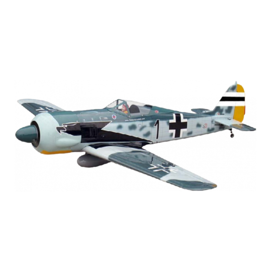
Requires : 0.46-0.55 cu. in. displacement 2-stroke
Wing Span
Wing Area
Flying Weight
Fuselage Length
Warning! This model is not a toy.
It is designed for maximum performance. Please seek advice if one is not familiar with this kind
of engine powered precision model. Operating this model without prior preparation may cause
injuries. Remember, safety is the most important thing. Always keep this instruction manual at
hand for quick reference.
The World Models
Manufacturing Co., Ltd.
www.theworldmodels.com
A322PO31941709
0.70-0.81 cu. in. displacement 4-stroke
6-channel radio w/ 6 standard servos.
Specifications
*Specifications are subject to change without notice.*
58.5 in / 1485 mm
539 sq in / 34.8 sq dm
6.5 Ib / 2970 g
49 in / 1250 mm
ALMOST-READY-TO-FLY(ARF)SERIES
INSTRUCTION MANUAL
( A322S )
FACTORY PRE-FABRICATED
MADE IN CHINA
Advertisement
Table of Contents

Related Manuals for THE WORLD MODELS A322S


Summary of Contents for THE WORLD MODELS A322S
- Page 1 INSTRUCTION MANUAL ( A322S ) Requires : 0.46-0.55 cu. in. displacement 2-stroke 0.70-0.81 cu. in. displacement 4-stroke 6-channel radio w/ 6 standard servos. Specifications Wing Span 58.5 in / 1485 mm Wing Area 539 sq in / 34.8 sq dm Flying Weight 6.5 Ib / 2970 g...
-
Page 2: Before You Begin
INDEX BEFORE YOU BEGIN PARTS LIST ASSEMBLY P.3-P.13 SAFETY PRECAUTIONS P.14 BEFORE YOU BEGIN Read through the manual before you begin, so you will have an overall idea of what to do. Check all parts. If you find any defective or missing parts contact your local dealer. Please DRY FIT and check for defects for all parts that will require CA or Epoxy for final assembly. -
Page 3: Parts List
Parts List 1.MAIN WING -- 1 pair 10.PUSHROD Ø1.8x740mm w/ Threads (For Rudder) -- 1 pc. SCREW PB2x16mm -- 3 pcs 2.M2 NUT -- 8 pcs TRI-HORN M3x22mm (S) PL4111301 -- 1 set SCREW PM2x6mm -- 8 pcs CLEVIS PL4112103 -- 1 pc. WASHER d2xD5mm -- 16 pcs FUEL TUBE Ø6x5mm -- 1 pc. -
Page 4: Bottom View
Main Wing Aileron Servo Lead Pre-glued Bottom View Retractable Landing Gear PM2x6mm Screw d2xD5mm M2 Nut Washer d2xD5mm PM2x6mm Washer d2xD5mm Washer d2xD5mm M2 Nut Washer 4.8V - 6.0V operation only, higher voltage Bottom View will burn out the retract motor. Main Wing Please dry fit wing joiner into left and right wing to make sure they fit with the proper dihedral angle, mark the wing joiner if necessary. - Page 5 Aileron Servo & Drop Tank Ø1mm pilot holes for World Models tri-horn are PB2x22mm Screw pre-drilled. Please look for pin-hole marks at PB2x18mm Screw under side of control surfaces. PWA2x8 mm Screw Fuel Tube Straper PWA2x8mm Ø 6x5mm 1.5mm PB 2 x 18mm PB 2 x 22mm Clevis Fuel Tube...
- Page 6 Flap Flaps up Flaps Down Lead to Flap Servo Lead to Flap Servo Lead to Aileron Servo Lead to Aileron Servo TWM PL8210010 CLEVIS WRENCH Straper Fuel Tube 6 x 5mm Ø Clevis Clevis Y-Type Pushrod 1.8 x 92mm Ø Ring A322PO31941709...
-
Page 7: Tail Landing Gear
Tail Landing Gear PA3x10mm Screw 2.1mm Collar Set Screw Tail Wheel Ø25mm 1.5mm 2.1mm Collar PA3x10mm 3mm Set Screw Bottom View Vertical Fin & Rudder (Vertical Fin) Pre-glued A=A' 2.5mm Completed A322PO31941709... -
Page 8: Stabilizer & Elevator
Stabilizer & Elevator (Stabi l i zer) (Mai n Wi ng) C=C' B=B' Temporary install the main wing, adjust leveling of the stabilizer to make it as parallel to the main wing as possible Completed Elevator Pushrod Ø1m m pilot holes for Wor ld Models tr i-hor n ar e pr e-dr illed. Please look for pin-hole m ar ks at under side of contr ol sur faces. -
Page 9: Engine Mount
Engine Mount M4x25mm Socket Head Screw Apply thread locker to screws Blind nuts are off-centered to keep d4xD9mm Washer the spinner at the fuselage axis. d4xD9mm Washer Socket Head Screw M4x25mm Engine Mount PL5111050 Bottom View Fuel Tank Double-side Tape 40x100mm Fuel Tank 380cc... - Page 10 Engine Installed Engine Position M3x30mm Socket Head Screw 130mm d3xD7mm Washer 5.12in M3 Nut Nu t d3xD7 Washer M3x30mm Socket Head Screw Plastic Tube d2xD3x230mm Throttle Pushwire Ø1.2x320mm Completed Cowling First insert the grommet to the cowling then apply screw. PWA2.6x12mm Screw Please refer to the attached sheet for usage of the...
-
Page 11: Radio Equipment
Servo Set 3x3mm Set Screw 3x3mm Set Screw Throttle Pushwire Linkage Connector Washer M2 Nut Washer 1.5mm Throttle Servo. 2mm Washer M2 Nut Please refer to the attached sheet for linkage connector installation. Radio Equipment Install and arrange the servos as shown in the diagram. J1(Pushrod Ø1.8x65mm) Elevator Pushrod Ø1.8x65mm... - Page 12 Main Wing HM4x40mm Screw d4.2xD14.5mm Washer Bottom View HM4x40mm Bottom View d4.2xD14.5mm Washer Canopy First insert the grommet to the canopy then apply screw. PWA2.3x8mm Screw d1.5xD6.5mm Silicon Grommet Pilot Silicon Grommet PWA2.3x8mm d1.5xD6.5mm Wire Ø1.8mm A322PO31941709 P.11...
- Page 13 Wing Setting Adjust the wing and fuselage configuration as shown in the diagrams. A=A` B=B` C=C` D=D` A322PO31941709 P.12...
-
Page 14: Control Throws
Control Throws Adjust the control throws as shown in the diagram. These throws are good for general flying. You can adjust according to your personal preference. Elevator 18mm 18mm Rudder 25mm 25mm Flaps (near fuselage ) 35mm Ailerons ( away from fuselage ) 12mm 12mm C.G. -
Page 15: Important Safety Precautions
Warning! I m portant S afety P recauti ons F irst tim e flyer sh o u ld n ever fly b y h im self / h erself. Assistan ce fro m exp erien ced flyer is ab so lu tely n ecessary. Pre - flig h t ad ju stm en t m u st b e d o n e b efo re flyin g , it is very d an g ero u s to fly a b ad ly p re - ad ju sted aircraft. - Page 16 LINKAGE CONNECTOR HW7111050 & HW7111060 Drill 2mm hole at servo horn. Insert linkage connector into servo horn. Make sure shoulder of screw is cleared from servo horn. Add washer to reduce play if necessary. Shoulder Tighten up the round nut against the shoulder.
- Page 17 Product Registration Form (US Customers) We would like to share with you any relevant information regarding your model, including product news and free upgrade parts when applicable. Please fill in the following and send to AirBorne Models, 4749-K,Bennett Drive, Livermore, CA 94551 USA. 1.
- Page 18 Usage of the transparent 3D template This transparent 3D template is used for position guidance of the actual cutting of the pre-painted cowling. Simply cut the transparent 3D template to fit your engine and exhaust pipe, then slide onto the actual cowling and use as template to mark the openings required for final cutting.
-
Page 19: Optional Parts
Optional Parts ACCESSORIES) Clevis Wrench 180mm Extension Code No. Size Package Code No. Size Package PL8210010 1 set KW0011800 180mm 1 set Small Clevis Large Clevis Special tool for clevis installation. Suitable for standard and small (EP) clevis. 180mm Y-Cord Code No. - Page 20 The World Models Manufacturing Co., Ltd. www.theworldmodels.com A322PO31941709...
Need help?
Do you have a question about the A322S and is the answer not in the manual?
Questions and answers