Table of Contents
Advertisement
Advertisement
Table of Contents

Related Manuals for Mitsubishi Electric FR-A8NP


Summary of Contents for Mitsubishi Electric FR-A8NP
-
Page 1: Instruction Manual
PRE-OPERATION INSTRUCTIONS INVERTER INSTALLATION Plug-in option FR-A8NP WIRING INSTRUCTION MANUAL INVERTER SETTING PROFIBUS-DP FUNCTIONS communication function PROFIBUS DEVICE DATA PPO TYPE SUPPORT SPECIFICATION PPO TYPE NON-SUPPORT SPECIFICATION TROUBLESHOOTING... -
Page 2: Safety Instructions
Thank you for choosing this Mitsubishi inverter plug-in option. This Instruction Manual provides handling information and precautions for use of this product. Incorrect handling might cause an unexpected fault. Before using this product, always read this Instruction Manual carefully to use this product correctly. Please forward this Instruction Manual to the end user. - Page 3 Additional instructions The following instructions must be also followed. If the product is handled incorrectly, it may cause unexpected fault, an injury, or an electric shock. Caution Transportation and mounting Do not install or operate the plug-in option if it is damaged or has parts missing. ...
-
Page 4: Table Of Contents
─ CONTENTS ─ 1 PRE-OPERATION INSTRUCTIONS Unpacking and product confirmation..........................7 Component names ................................8 Specifications ..................................9 1.3.1 Inverter option specifications ..............................9 1.3.2 Communication specifications .............................. 9 2 INSTALLATION Pre-installation instructions ............................10 Installation procedure ..............................11 Node address switch setting ............................15 3 WIRING Terminals..................................16 Wiring....................................17 4 INVERTER SETTING... - Page 5 Input to the inverter from the network.........................33 6 PROFIBUS DEVICE DATA Device data (GSD file) ..............................34 Slave user parameter ..............................39 7 PPO TYPE SUPPORT SPECIFICATION PROFIBUS profiles ................................40 7.1.1 Setting the PROFIBUS format (Pr.1110) ..........................40 ID definitions ..................................42 Buffer memory configuration ............................43 Buffer memory details..............................45 Outline of PNU ................................54 PROFIBUS PNU................................55...
- Page 6 8 PPO TYPE NON-SUPPORT SPECIFICATION PROFIBUS profiles ................................72 ID definitions ..................................73 Buffer memory configuration ............................74 Buffer memory details..............................75 Outline of PNU ................................79 PROFIBUS PNU (module type A5NP) ..........................80 8.6.1 Real-time monitor area (IND=H0000 (IND=H00, PP=H00)) ....................80 8.6.2 System environment variable (sev) area (IND = H01PP (IND = H01, PP = H00, H01)) ............. 81 Standard parameters..............................85 8.7.1 Normal parameter area (IND = H0200 (IND = H02, PP = H00))..................
- Page 7 MEMO...
-
Page 8: Pre-Operation Instructions
PRE-OPERATION INSTRUCTIONS Unpacking and product confirmation Take the plug-in option out of the package, check the product name, and confirm that the product is as you ordered and intact. This product is a plug-in option for the FR-A800/F800 series inverter. ... -
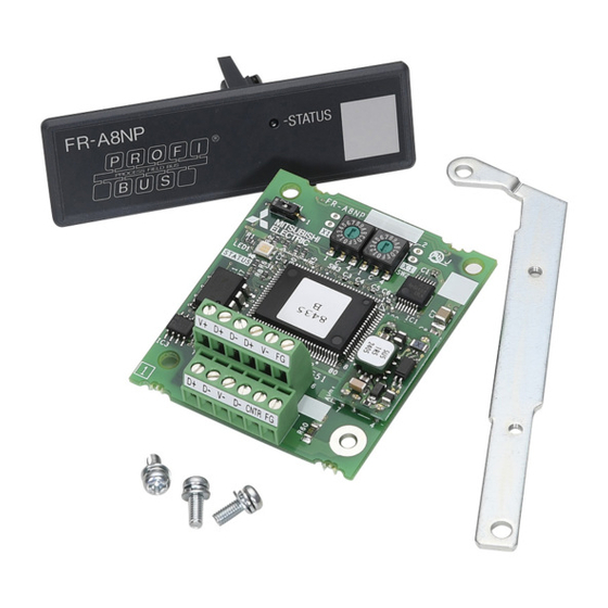
Page 9: Component Names
Component names Front view Pin assignment Rear view (SW2) (SW3) Symbol Name Description Refer to page Mounting hole Fixes the option to the inverter with screws, or installs spacers. Terminal block Connect the communication cable. ON/OFF indicator of the LED indicates inverter operation status. LED status Description Inverter power OFF... -
Page 10: Specifications
Specifications 1.3.1 Inverter option specifications Type Inverter plug-in option type Number of nodes occupied One inverter occupies one node. Connection cable Cable which supports 12.0 Mbps communication (EIA-485(RS-485) standard) 1.3.2 Communication specifications Wiring length 1200 m or less 9600 bps, 19.2 Kbps, 93.75 Kbps Wiring length 600 m or less 187.5 Kbps Communication speed... -
Page 11: Installation
INSTALLATION Pre-installation instructions Check that the inverter's input power and the control circuit power are both OFF. Caution With input power ON, do not install or remove the plug-in option. Otherwise, the inverter and plug-in option may be damaged. ... -
Page 12: Installation Procedure
Installation procedure Installing the communication option LED display cover (1) Remove the inverter front cover. (Refer to Chapter 2 of the Instruction Manual (Detailed) of the inverter for details on how to remove the front cover.) Mount the cover for displaying the operation status indication LED for the communication option on the inverter front cover. (2) Cut off hooks on the rear of the inverter front cover with nipper, etc. - Page 13 Installing the option (1) For the two mounting holes (as shown in the next page) Inverter side that will not be tightened with mounting screws, insert option connector spacers. Spacer (2) Fit the connector of the plug-in option to the guide of the connector on the inverter unit side, and insert the plug-in option as far as it goes.
- Page 14 Connector 3 Do not insert the plug-in option to the connector 2 or 3. Mounting screw Spacer Connector 2 Connector 1 Spacer Mounting screw Mounting screw Earth plate Insertion positions for screws and spacers INSTALLATION...
- Page 15 NOTE • When mounting/removing the plug-in option, hold the sides of the option. Do not press on the parts on the option circuit board. Stress applied to the parts by pressing, etc. may cause a failure. • Caution must be applied to mounting screws falling off when removing and mounting the plug-in option. •...
-
Page 16: Node Address Switch Setting
Node address switch setting Set the node address between "H00" and "H7D" using the node address switches on the FR-A8NP board. (Refer to page The setting is applied at the next power-ON. Set the arrow () of the corresponding switches to a number or an alphabet to set a desired address. -
Page 17: Wiring
WIRING Terminals Terminal no. Terminal name Definition V+ (VP) Voltage output (approx. 5 V to V-) D+ (RXD/TXD-P) Sends and receives PROFIBUS signal+ (B-line) D+ (RXD/TXD-P) Sends and receives PROFIBUS signal+ (B-line) V+ D+ D- D+ V- FG D- (RXD/TXD-N) Sends and receives PROFIBUS signal- (A-line) D- (RXD/TXD-N) -
Page 18: Wiring
Wiring Use the network connection cable which supports 12.0 Mbps communication. (1) Strip off the sheath of the PROFIBUS communication dedicated cable and wind wires and shield cables to use. Strip off the sheath for the below length. If the length of the sheath peeled is too long, a short circuit may occur with neighboring wires. - Page 19 (2) Loosen the terminal screw and insert the cable into the terminal. Tighten each cable with fixing screws to the recommended tightening torque. <Cable connection example> <Connection example of multiple inverters> To next inverter D+ D- D+ D- D+ D- To master Screw size Tightening torque...
- Page 20 (3) Terminating resistor Connect terminating resistors to the both ends of a network if the both ends are FR-A8NP-mounted inverters. Connection example Inverter Inverter Master station PLC etc. Terminating resistor Terminating resistor Power Power Motor Motor supply supply PROFIBUS communication cable R1=390Ω...
-
Page 21: Inverter Setting
INVERTER SETTING Parameter list The following parameters are used for the communication option (FR-A8NP). Set the values according to need. Minimum setting Initial Refer to Name Setting range group increments value page D000 Operation mode selection 0 to 4, 6, 7... -
Page 22: Inverter Setting
0, 1 Parameters which can be displayed when the plug-in option (FR-A8NP) is mounted. Parameters which can be displayed when the plug-in option (FR-A8AP) is mounted. The setting is applied after an inverter reset or power-ON. -
Page 23: Operation Mode Setting
Operation mode setting 4.2.1 Operation mode switching and communication startup mode (Pr.79, Pr.340) Operation mode switching conditions Operation mode switching conditions • The inverter is at a stop; • Both the STF and STR signals are off; and • The Pr.79 Operation mode selection setting is correct. (Set with the operation panel of the inverter.) ... - Page 24 Pr.340 Pr.79 Operation mode at power ON or power Operation mode switchover setting setting restoration 0 (initial Switching among the External, PU, and NET operation External operation mode value) mode is enabled. PU operation mode PU operation mode fixed Switching between the External and Net operation mode is External operation mode enabled.
- Page 25 Pr.340 Pr.79 Operation mode at power ON or power Operation mode switchover setting setting restoration Switching between the PU and NET operation mode is NET operation mode enabled. PU operation mode Same as when Pr.340 = "0" NET operation mode NET operation mode fixed 10, 12 ...
-
Page 26: Operation At Communication Error Occurrence
Operation at communication error occurrence 4.3.1 Operation selection at communication error occurrence (Pr.500 to Pr.502, Pr.779) You can select operations at communication error occurrences by setting Pr.500 to Pr.502, Pr.779 under network operation. Waiting time for the communication line error output after a communication error Waiting time for the communication error output after a communication line error occurrence can be set. - Page 27 Displaying and clearing the communication error count The cumulative count of communication error occurrences can be displayed. Write "0" to clear this cumulative count. Minimum setting Name Setting range Initial value increments Communication error occurrence count display Normal Error Normal Error Count timing depending on...
- Page 28 About setting • Operation at an error occurrence Fault description Pr.502 setting Operation Indication Fault output Communication line Continued Normal indication Not provided 0, 3 Coast to stop E. 1 lit Provided Communication option itself 1, 2 Decelerated to stop E.
- Page 29 • Operation at error removal Fault description Pr.502 setting Operation Indication Fault output Kept stopped E.OP1 kept lit Kept provided Communication line Restart Normal indication Not provided Normal operation 0, 3 Communication option Kept stopped E. 1 kept lit Kept provided itself 1, 2 NOTE...
-
Page 30: Fault And Measures
4.3.2 Fault and measures Inverter operation in each operation mode at error occurrences Operation mode Location Status Network operation External operation PU operation Inverter operation Inverter trip Inverter trip Inverter trip Inverter Data communication Continued Continued Continued Inverter operation Inverter trip Continued Continued... -
Page 31: Inverter Reset
Inverter reset Operation conditions of inverter reset Which resetting method is allowed or not allowed in each operation mode is described below. Operation mode Resetting method Network External PU operation operation operation Inverter reset (Class 0x2A, Instance 1, Attribute 101) (Refer Allowed Disallowed Disallowed... - Page 32 Error reset operation selection at inverter fault An error reset command from communication option can be invalid in the External operation mode or PU operation mode. Use Bit2 of Byte0 of Output Instance 20, 21, 126, or 129 and Class 0x29 Instance 1 Attribute 12 for error reset commands via the network.
-
Page 33: Functions
FUNCTIONS Output from the inverter to the network Main items to be output from the inverter (FR-A8NP) to the network and their descriptions are explained below. Refer to page PPO type PPO type Item Description support non-support specification specification Monitor various items such as inverter output frequency and output Inverter monitor current. -
Page 34: Input To The Inverter From The Network
Input to the inverter from the network Main items which can be commanded from the network to the inverter and their descriptions are explained below. Refer to page PPO type PPO type Item Description support non-support specifications specifications Frequency setting Set the running frequency of the inverter. -
Page 35: Profibus Device Data
PROFIBUS DEVICE DATA Device data (GSD file) A GSD file is required to connect the inverter (FR-A8NP) to the Profibus network and use Profibus configuration software. The GSD file contains information on the communication setting of the inverter (FR-A8NP). GSD file can be downloaded from the web site. - Page 36 • Details of the GSD file Parameter Value Description #Profibus_DP File header GSD_Revision ID version of GSD file Vendor_Name "Mitsubishi Electric" Manufacturer name Model_Name "FR-A8NP" Product name Revision — Product version Ident_Number H0EA8 Device number obtained from Profibus Nutzer Organization Protocol_Ident PROFIBUS-DP is 0 fixed.
- Page 37 Parameter Value Description MaxTsdr_9.6 Longest time 15 bit times at communication speed 9600 bps MaxTsdr_19.2 Longest time 15 bit times at communication speed 19.2 Kbps MaxTsdr_93.75 Longest time 15 bit times at communication speed 93.75 Kbps MaxTsdr_187.5 Longest time 15 bit times at communication speed 187.5 Kbps MaxTsdr_500 Longest time 15 bit times at communication speed 500 Kbps MaxTsdr_1.5M...
- Page 38 Parameter Value Description Max_Data_Len Input and output data: Maximum 28 + 28 = 56 bytes Fail_Safe Failsafe not supported Max_Diag_Data_Len Diagnostic data of 6 bytes secured (no external diagnosis) Slave_Family Drives defined as function class (Main Family) PrmText Text selection 1 registration Text(0) "No byte swapping"...
- Page 39 Parameter Value Description EndModule Module "PPO type 4" HF5 PPO type 4 selection EndModule Module "PPO type 5" HF3, HF9 PPO type 5 selection EndModule Module "500 series" H75 FR-A5NP intercompatibility protocol selection EndModule Description is not included in the ASCII file itself. ...
-
Page 40: Slave User Parameter
Slave user parameter By changing the slave user parameter value, you can use the byte swapping function (byte inversion function). Setting "1" at Address H1 (Bit 0) enable the byte swapping function. Since " " is an unused bit, set "0". —... -
Page 41: Ppo Type Support Specification
PPO TYPE SUPPORT SPECIFICATION PROFIBUS profiles The option unit operates as a "slave of the PROFIBUS DP master" or a "controller equivalent to PROFIBUS DP master class 1 on an RS-485 network". The PROFIBUS profile (data buffer) can be selected from among six different types, "PPO type1" to "PPO type5", and "A5NP". (For the module type "A5NP"... - Page 42 Standard format (Pr.1110 = "0" (initial value)) The following shows the configuration of the PPO type in the standard format. Module type Input Data : 6 Words STW/ HSW/ PPO type1 Output Data : 6 Words Input Data : 10 Words STW/ HSW/ ECW/...
-
Page 43: Id Definitions
ID definitions Definition PNU number (PNU) and task or response Id (AK) Sub-Index number and Ext-Index number (Refer to page Set 0 since high bits (Bits 16 to 31) are not used. Low bits (Bits 0 to 15): Parameter value STW: Control Word (command request) ... -
Page 44: Buffer Memory Configuration
Buffer memory configuration The buffer memory configuration is shown below. Master Slave (command request) Slave Master (command response) 15 14 13 12 11 10 9 8 7 6 5 4 3 2 1 0 bit 15 14 13 12 11 10 9 8 7 6 5 4 3 2 1 0 PNU(parameter number) PNU(parameter number) Task... - Page 45 15 14 13 12 11 10 9 8 7 6 5 4 3 2 1 0 15 14 13 12 11 10 9 8 7 6 5 4 3 2 1 0 ESW (Standard format) ECW (Standard format) Command count Command count 0 0 0 0 15 14 13 12 11 10 9 8 7 6 5 4 3 2 1 0...
-
Page 46: Buffer Memory Details
Buffer memory details The following indicates the buffer memory details of the Profibus profiles. PKW Name Definition 0 to 10 PNU number Not used (0 is set) [Command request] Value Operation No task Parameter value is requested (read request) Parameter value (word) is changed (write request) Parameter value (array) is requested (read request) Parameter value (array word) is changed (write request) - Page 47 Name Definition Ext-Index number 0 to 7 When Bit 0 (extended parameter access) = "1" and AK = "1 or 2", the PNU value (parameter number) plus 1000 can be read or written. Sub-Index number 8 to 15 At command request, set this number when AK ="6, 7". PNU read value/write value When command response AK ="7"...
- Page 48 PZD Name Definition — 0 to 2 Not used (1 is set) Control enable 0: Inverter output shutoff, 1: Inverter output shutoff is cancelled — 4 to 6 Not used (1 is set) [At inverter error] 0: No action Fault reset 1: Fault reset (Reset).
- Page 49 Name Definition — 0 to 2 Not used (1 is returned) 0: Inverter normal Fault 1: Inverter alarm occurrence — 4, 5 Not used (1 is returned) Power-on inhibit 0 is returned Command execution normal Alarm Command execution error — Not used (0 is returned) Control request 1 is returned...
- Page 50 Name Definition Terminal RH function High speed operation command Terminal RM function Middle-speed operation command Terminal RL function Low-speed operation command Functions assigned to terminal RH, RM, Terminal JOG function Jog operation command RL, JOG, AU and CS are activated. Terminal AU function Current input selection ...
- Page 51 Name Definition Terminal RH function High speed operation command Terminal RM function Middle-speed operation command Terminal RL function Low-speed operation command Functions assigned to terminal RH, RM, Terminal JOG function Jog operation command RL, JOG, AU and CS are activated. Terminal AU function Current input selection ...
- Page 52 Name Definition SU signal 0: OFF, 1: ON (up to frequency) OL signal 0: OFF, 1: ON (overload alarm) IPF signal 0: OFF, 1: ON (an instantaneous power failure or undervoltage occurs) The function assigned to the terminal Terminal RUN function Inverter running ...
- Page 53 Name Definition Monitor item assignment Function number of the monitor item assigned to STS1 to STS7 (Refer to page 0 to 7 to STS1 to STS7 REF1 to REF7 (when AK = "15") Command assignment 8 to 15 Function number of the command assigned to REF1 to REF7 (Refer to page to REF1 to REF7 Monitor item assignment...
- Page 54 When the slave side is busy, request from the master is invalid. Therefore, the same request must be sent again. The response data of the FR-A8NP during Busy status is as follows.
-
Page 55: Outline Of Pnu
Outline of PNU You can use the PNU to make inverter settings from the network. The data used with the network is denoted PNU (P) to differentiate it from the parameter (Pr.) of the inverter. This chapter explains the module type "PPO type 1" to "PPO type 5". NOTE •... -
Page 56: Profibus Pnu
PROFIBUS PNU 7.6.1 Real-time monitor Different inverter data can be monitored using the master. The data type for each monitor item is AUs16. The PNU number for the real-time monitor is 1. The monitored item and the sub-index number are the same as those of the RS-485 communication dedicated monitor of the inverter. -
Page 57: Parameter Clear
7.6.2 Parameter clear Parameter clear can be performed from the master. Item Data definition Data type P2.2 Parameter clear H965A AUs16 P2.3 All parameter clear H99AA AUs16 P2.5 Parameter clear H5A96 AUs16 P2.6 All parameter clear HAA99 AUs16 P2.8 Faults history clear H0000... -
Page 58: Terminal Input Read
7.6.5 Terminal input read Analog input values of terminals 2, 4, and 1 can be read. Item Data definition Data type P5.1 Terminal 2 input value read Terminal 2 input value (%) is read. AUs16 P5.2 Terminal 4 input value read Terminal 4 input value (%) is read. - Page 59 • For details of the commands (settings) which can be assigned to REF1 to REF7, refer to the following table. Setting Resolution Condition to enable a command given by the master Refer Description Unit value of the setting via the Profibus communication to page No function —...
-
Page 60: Sts Monitor Function (Available Only When The Extended Format Is Selected) (Only For The Fr-A800 Series)
7.6.8 STS monitor function (available only when the extended format is selected) (only for the FR-A800 series) When AK = "15", monitor numbers can be assigned to Bits 0 to 7 of REF1 to REF7. Assigned items can be monitored in STS1 to STS7 when AK ... -
Page 61: Faults History Read
7.6.10 Faults history read • Fault records of past eight faults occurred in the inverter can be read. (For the data codes or details of fault records, refer to the Instruction Manual (Detailed) of the inverter.) Item Data definition Data type P947.1 Data code of the fault record P947.1 to P947.8... - Page 62 • Energization time (fault monitor) for past eight alarms at the inverter alarm occurrence can be read. Item Data definition Data type P948.1 Energization time Latest fault monitor energization P948.1 to P948.8 AUs16 time read P948.2 to P948.8 All 0 P948.9 Energization time Energization time of second...
- Page 63 • Output frequency, output current and output voltage for past eight alarms at the inverter alarm occurrence can be read. Item Data definition Data type P949.1 Output frequency P949.2 Output current Latest fault monitor frequency, P949.1 to P949.8 AUs16 current and voltage read P949.3 Output voltage P949.4 to P949.8...
- Page 64 Item Data definition Data type P949.41 Output frequency P949.42 Output current Sixth fault monitor frequency, P949.41 to P949.48 AUs16 current and voltage in past read P949.43 Output voltage P949.44 to P949.48 All 0 P949.49 Output frequency P949.50 Output current Seventh fault monitor frequency, P949.49 to P949.56 AUs16 current and voltage in past read...
-
Page 65: Pnu List Read
7.6.11 PNU list read The usable PNU numbers can be read. Item Data definition Data type P980.1 to 116 P981.1 to 116 P982.1 to 116 P983.1 to 116 P984.1 to 116 PNU list read Usable PNU numbers are read in sorted status. AUs16 P985.1 to 116 P986.1 to 116... -
Page 66: Standard Parameters
NOTE • Write to Pr.77 and Pr.79 is not allowed from the network with FR-A8NP. (Read is allowed.) • To read or write parameter of Pr.1000 or later, set Bit 0 of the ext-index number (extended parameter access) = "1". - Page 67 The following parameters require the sub-index number for the PNU. Data Name Type C0 (900) P1900.1 FM/CA terminal calibration AUs16 C1 (901) P1901.1 AM terminal calibration AUs16 C2 (902) P1902.1 Terminal 2 frequency setting bias frequency AUs16 C3 (902) P1902.2 Terminal 2 frequency setting bias AUs16 125 (903)
- Page 68 Data Name Type C9 (930) P1930.2 Current output bias current AUs16 C10 (931) P1931.1 Current output gain signal AUs16 C11 (931) P1931.2 Current output gain current AUs16 C38 (932) P1932.1 Terminal 4 bias command (torque) AUs16 C39 (932) P1932.2 Terminal 4 bias (torque) AUs16 C40 (933) P1933.1...
-
Page 69: Profibus-Dp Communication Function Setting
PROFIBUS-DP communication function setting 7.8.1 PROFIBUS communication command source setting (Pr.1109) (only for the FR- A800 series) Use Pr.1109 PROFIBUS communication command source selection to set the input source for the magnetic flux command, speed control P gain, speed control integral time, and droop gain in the buffer memory REF1 to REF7 in the extended format of the PROFIBUS profiles, PPO type 2 and PPO type 5. -
Page 70: Torque Command / Torque Limit Via Profibus Communication (Pr.804) (Only For The Fr-A800 Series)
Torque command by the parameter setting (Pr.805 or Pr.806) communication is not available. (-400% to 400%) Torque command via PROFIBUS communication (FR-A8NP) Input via PROFIBUS • Torque command by the parameter setting (Pr.805 or Pr.806) communication is available. (-400% to 400%) ... -
Page 71: Torque Bias Selection (Pr.840) (Only For The Fr-A800 Series)
7.8.3 Torque bias selection (Pr.840) (only for the FR-A800 series) Under speed control under vector control, setting Pr.840 Torque bias selection = "24 or 25" enables torque bias setting via PROFIBUS communication. Initial Setting Name Description value range Set the torque bias amount using contact signals (X42, X43) in Pr.841 to Pr.843. -
Page 72: Frequency Command With Sign (Pr.541)
7.8.4 Frequency command with sign (Pr.541) By adding a sign to the frequency command value or the speed limit value, the start command (forward/reverse rotation) can be inverted to start operation. Select whether or not to use a sign for the frequency command value / speed limit value. Name Initial value Setting range... -
Page 73: Ppo Type Non-Support Specification
Module type is changed with the slave module setting. For details, refer to the instruction manual of the Network Master Configuration Software. NOTE • The "A5NP" profile is compatible with the FR-A5NP profile. Use "A5NP" profile when replacing the FR-A5NP with FR-A8NP, etc. The configuration of the "A5NP" is as follows. Module type... -
Page 74: Id Definitions
ID definitions Definition PNU number (PNU) and task or response Id (AK) Index number (Refer to page Set 0 since high bits (Bits 16 to 31) are not used. Lower (Bits 0 to 15): Parameter value Bits 0 to 7: Inverter status (Command response) ... -
Page 75: Buffer Memory Configuration
Buffer memory configuration Master Slave (command request) Slave Master (command response) 15 14 13 12 11 10 9 8 7 6 5 4 3 2 1 0 bit 15 14 13 12 11 10 9 8 7 6 5 4 3 2 1 0 PNU (parameter number) PNU (parameter number) Task... -
Page 76: Buffer Memory Details
Buffer memory details The following indicates the buffer memory details of the PROFIBUS profiles. PKW Name Definition 0 to 10 PNU number (Together, the PNU and the IND define which data word is being accessed.) Not used (0 is set) [Command request] Value Operation... - Page 77 Name Definition Page Index : • If IND = 1 (system environment variables (sev) area), the PP values specify different blocks of sev's: PP = 0 : sev_I, block I 0 to 7 PP = 1 : sev_II, block II (alarm history) PP = 2 : sev_III, block III (For details, refer to page...
- Page 78 PZD Name Definition 0 : OFF RUN signal 1 : ON (inverter running) 0 : OFF FWD signal 1 : ON (forward rotation operation being performed) 0 : OFF REV signal 1 : ON (reverse rotation operation being performed) •...
- Page 79 NOTE • Only when the contents of the command request (request for changing the inverter setting: PKW) from the master changed, the inverter processes the request. If the contents of the command request are identical with those of the last request, the inverter does not process the request. (The received request is cleared.) For instance, while the master keeps sending the "network operation mode enable"...
-
Page 80: Outline Of Pnu
Outline of PNU You can use the PNU to make inverter settings from the network. The data used with the network is denoted PNU (P) to differentiate it from the parameter (Pr.) of the inverter. This chapter explains the module type "A5NP". NOTE •... -
Page 81: Profibus Pnu (Module Type A5Np)
PROFIBUS PNU (module type A5NP) 8.6.1 Real-time monitor area (IND=H0000 (IND=H00, PP=H00)) Different inverter data can be monitored using the master. Item Increments H0000 H0 Output frequency 0.01 Hz H0000 H1 Output current 0.01 A/0.1 A H0000 H2 Output voltage 0.1 V NOTE •... -
Page 82: System Environment Variable (Sev) Area (Ind = H01Pp (Ind = H01, Pp = H00, H01))
8.6.2 System environment variable (sev) area (IND = H01PP (IND = H01, PP = H00, H01)) SEV Interface (IND = H01, PP = H00, SEV_I, Block I) Parameter clear Inverter reset and parameter clear can be performed from the master. Item Data definition H0100... - Page 83 Inverter status/operation command The inverter status can be monitored and operation command can be given from the master. Item Inverter status For details, refer to ZSW on page Run command Name Definition — Not used (0 is set) Terminal STF Forward rotation command Terminal STR Reverse rotation command...
- Page 84 Operation mode read/write Read/write of the operation mode can be performed from the master. Item Data definition External operation mode : H10 H0100 Operation mode PU operation mode : H11 (When Pr.79 = "6") Network operation mode : H14 ...
- Page 85 Faults History (IND = H01, PP = H01, SEV_II, Block II) The past eight inverter fault records can be read. (For the data codes or details of fault records, refer to the Instruction Manual (Detailed) of the inverter.) Item H0101 Latest fault/Batch clearing of fault records ...
-
Page 86: Standard Parameters
Maximum frequency Minimum frequency Base frequency H0200 Multi-speed setting (high speed) Multi-speed setting (middle speed) Multi-speed setting (low speed) NOTE • Write to Pr.77 and Pr.79 is not allowed from the network with FR-A8NP. (Read is allowed.) PPO TYPE NON-SUPPORT SPECIFICATION... -
Page 87: Pr.900 To Calibration Parameter (Frequency) Area (Ind=H0300 (Ind=H03, Pp=H00))
8.7.2 Pr.900 to calibration parameter (frequency) area (IND=H0300 (IND=H03, PP=H00)) The following parameters can be set with IND=H0300. Refer to the Instruction Manual (Detailed) of the inverter for details of the parameters. Name H0300 C0(900) FM/CA terminal calibration H0300 C1(901) AM terminal calibration H0300 C2(902) -
Page 88: Pr.900 To Calibration Parameter (%) Area (Ind=H0400 (Ind=H04, Pp=H00))
8.7.3 Pr.900 to calibration parameter (%) area (IND=H0400 (IND=H04, PP=H00)) The following parameters can be set with IND=H0400. Refer to the Instruction Manual (Detailed) of the inverter for details of the parameters. Name H0400 C3(902) Terminal 2 frequency setting bias H0400 C4(903) Terminal 2 frequency setting gain... -
Page 89: Troubleshooting
Set the same node address with the master on the PROFIBUS communication is not inverter (FR-A8NP) using the node address switches. established with the master. (Turn OFF, then ON the power supply after changing the (Incorrect node address setting) node address setting on the inverter (FR-A8NP).) - Page 90 Operation LED on panel display Possible cause Checkpoint / troubleshooting FR-A8NP on the inverter Check the network setting with the PROFIBUS-DP The network setting is incorrect. network configuration software. The network is unstable. The inverter is affected by the Check if any network error has occurred in the other other nodes.
- Page 91 REVISIONS *The manual number is given on the bottom left of the back cover. Print Date *Manual Number Revision Feb. 2014 IB(NA)-0600528ENG-A First edition Addition Oct. 2014 IB(NA)-0600528ENG-B • Compatibility with the FR-F800 series Modification Jan. 2016 IB(NA)-0600528ENG-C • Terminal name IB(NA)-0600528ENG-C...
- Page 92 INVERTER HEAD OFFICE: TOKYO BUILDING 2-7-3, MARUNOUCHI, CHIYODA-KU, TOKYO 100-8310, JAPAN IB(NA)-0600528ENG-C(1601)MEE Printed in Japan Specifications subject to change without notice.
Need help?
Do you have a question about the FR-A8NP and is the answer not in the manual?
Questions and answers