Mitsubishi Electric 800 Series Instruction Manual
Plug-in option, profibus-dp communication function
Hide thumbs
Also See for 800 Series:
- Instruction manual (727 pages) ,
- Instruction manual (function (534 pages) ,
- Manual (183 pages)
Table of Contents
Advertisement
Quick Links
Advertisement
Table of Contents

Related Manuals for Mitsubishi Electric 800 Series


Summary of Contents for Mitsubishi Electric 800 Series
- Page 1 PRE-OPERATION INSTRUCTIONS INVERTER Plug-in option INSTALLATION FR-A8NP E KIT WIRING INSTRUCTION MANUAL INVERTER SETTING PROFIBUS-DP FUNCTIONS communication function PROFIBUS DEVICE DATA PPO TYPE SUPPORT SPECIFICATION PPO TYPE NON-SUPPORT SPECIFICATION TROUBLESHOOTING...
-
Page 2: Safety Instructions
Safety instructions Thank you for choosing this Mitsubishi Electric inverter plug-in option. This Instruction Manual provides handling information and precautions for use of this product. Incorrect handling might cause an unexpected fault. Before using this product, read all relevant instruction manuals carefully to ensure proper use. - Page 3 Additional instructions The following instructions must be also followed. If this product is handled incorrectly, it may cause unexpected fault, an injury, or an electric shock. CAUTION Transportation and installation Do not install or operate this product if it is damaged or has parts missing. ...
-
Page 4: Table Of Contents
─ CONTENTS ─ Safety instructions 1 PRE-OPERATION INSTRUCTIONS Unpacking and product confirmation..........................6 Component names ................................8 Specifications ..................................9 1.3.1 Inverter option specifications ..............................9 1.3.2 Communication specifications .............................. 9 2 INSTALLATION Pre-installation instructions ............................10 Installation procedure ..............................10 Node address switch setting ............................18 3 WIRING Terminals..................................19 Wiring....................................20... - Page 5 5 FUNCTIONS Output from the inverter to the network........................35 Input to the inverter from the network.........................36 6 PROFIBUS DEVICE DATA Device data (GSD file) ..............................37 Slave user parameter ..............................41 7 PPO TYPE SUPPORT SPECIFICATION PROFIBUS profiles ................................42 ID definitions ..................................43 Buffer memory configuration ............................44 Buffer memory details..............................45 Outline of PNU ................................51...
- Page 6 8 PPO TYPE NON-SUPPORT SPECIFICATION PROFIBUS profiles ................................63 ID definitions ..................................64 Buffer memory configuration ............................65 Buffer memory details..............................66 Outline of PNU ................................70 PROFIBUS PNU (module type A5NP) ..........................70 8.6.1 Real-time monitor area (IND = H0000 (IND = H00, PP = H00)) ..................70 8.6.2 System environment variable (sev) area (IND = H01PP (IND = H01, PP = H00, H01)) .............
-
Page 7: Pre-Operation Instructions
PRE-OPERATION INSTRUCTIONS Unpacking and product confirmation Take the plug-in option out of the package, check the product name, and confirm that the product is as you ordered and intact. This product is a plug-in option for the FR-E800 series inverter. ... - Page 8 SERIAL number check The FR-A8NP can be used for the inverter models listed below with the following SERIAL number or later. Check the SERIAL number indicated on the inverter rating plate or package. Rating plate example □□ ○○ ○ ○○○○○○ Symbol Year Month Control number SERIAL SERIAL...
-
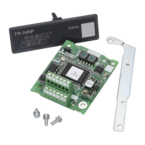
Page 9: Component Names
Component names Front view Pin assignment Rear view SW1 X16 Symbol Name Description Refer to page Mounting hole Fixes the option to the inverter with screws, or installs spacers. Terminal block Connect the communication cable. ON/OFF indicator of the LED indicates inverter operation status. OFF: Inverter power OFF ... -
Page 10: Specifications
Specifications 1.3.1 Inverter option specifications Item Description Type Inverter plug-in option type Number of nodes occupied One inverter occupies one node. Connection cable Cable which supports 12.0 Mbps communication (EIA-485 (RS-485) standard) 1.3.2 Communication specifications Wiring length Communication speed 1200 m or less 9600 bps, 19.2 Kbps, 93.75 Kbps 600 m or less 187.5 Kbps... -
Page 11: Installation
INSTALLATION Pre-installation instructions Check that the inverter's input power and the control circuit power are both OFF. CAUTION • Do not install or remove this product while the inverter power is ON. Doing so may damage the inverter or this product. •... - Page 12 For the FR-E820-0175(3.7K) or lower, FR-E840-0170(7.5K) or lower, and FR-E860-0120(7.5K) or lower Remove the inverter front cover. (Refer to the FR-E800 Instruction Manual (Connection) for instructions to remove the cover.) Use a nipper or the like to cut off the bottom of the front cover for plug-in option. Ensure no burr is left.
- Page 13 Remove the body screws of the inverter, then install the hexagon spacers to the inverter (tightening torque 0.33 to 0.40 N·m). Fit the junction connector, which has been connected to the plug-in option, to the guide of the option connector on the inverter, and insert the junction connector as far as it goes.
- Page 14 For the FR-E820-0240(5.5K) or higher Remove the upper front cover and the lower front cover from the inverter. (Refer to the FR-E800 Instruction Manual (Connection) for instructions to remove the covers.) Use a nipper or the like to cut off the dummy cover of the lower front cover in order to install the option small cover. Upper front cover Dummy cover Ensure no burr is left.
- Page 15 Remove the body screws of the inverter, then install the hexagon spacers to the inverter (tightening torque 0.33 to 0.40 N·m). Fit the junction connector, which has been connected to the plug-in option, to the guide of the option connector on the inverter, and insert the junction connector as far as it goes.
- Page 16 Install the lower front cover to the inverter. 6. Plug-in option 7. Mounting 5. Hexagon spacer screw 10. Front cover for plug-in option 4. Junction connector 9. Recessed neck screw 7. Mounting screw 4. Straight spacer 10. Option small cover 11.
- Page 17 Insertion positions for screws and spacers Mounting screw Straight spacer Connector L-shaped spacer Mounting screw Insertion positions for screws and spacers INSTALLATION...
- Page 18 NOTE • When the junction connector is installed to the plug-in option, the option is fixed with the hooks of the connector. The junction connector cannot be removed from the plug-in option. • When removing the front cover for plug-in option from the inverter, note that the recessed neck screw cannot be removed from the front cover for plug-in option.
-
Page 19: Node Address Switch Setting
Node address switch setting Set the node address between "H00" and "H7D" using the node address switches on the FR-A8NP board. (Refer to page The setting is applied at the next power-ON. Set the arrow ( ) of the corresponding switches to a number or an alphabet to set a desired address. ... -
Page 20: Wiring
WIRING Terminals V+ D+ D- V- FG D+ D- D- CNTR FG Terminal no. Terminal name Definition Voltage output (approx. 5 V to V-) V+ (VP) D+ (RXD/TXD-P) Sends and receives PROFIBUS signal+ (B-line) Sends and receives PROFIBUS signal+ (B-line) D+ (RXD/TXD-P) D- (RXD/TXD-N) Sends and receives PROFIBUS signal- (A-line) -
Page 21: Wiring
Wiring Use the network connection cable which supports 12.0 Mbps communication. Strip off the sheath of the PROFIBUS communication dedicated cable and wind wires and shield cables to use. Strip off the sheath for the below length. If the length of the sheath peeled is too long, a short circuit may occur with neighboring wires. - Page 22 NOTE Ferrule terminal commercially available (as of December 2019. The product may be changed without notice.) Ferrule terminal model Terminal Crimping tool Manufacturer Wire size (mm screw size name with insulation sleeve without insulation sleeve AI 0,34-6TQ A 0,34-7 Phoenix Contact CRIMPFOX 6 Co., Ltd.
- Page 23 Terminating resistor Connect terminating resistors to the both ends of a network if the both ends are FR-A8NP-mounted inverters. Connection example Inverter Inverter Master station PLC etc. Terminating resistor Terminating resistor Power Power Motor Motor supply supply PROFIBUS communication cable R1=390: 2% 1/4W R2=220:...
-
Page 24: Inverter Setting
INVERTER SETTING Parameter list The following parameters are used for the communication option (FR-A8NP). Set the values according to need. Minimum setting Initial Refer to Pr. group Name Setting range increments value page D000 Operation mode selection 0 to 4, 6, 7 D010 Communication operation command source 0, 1... -
Page 25: Operation Mode Setting
Operation mode setting 4.2.1 Operation mode switching and communication startup mode (Pr.79, Pr.340) Operation mode switching conditions Check the following before switching the operation mode. • The inverter is at a stop. • Both the STF and STR signals are off. •... - Page 26 Operation mode at power ON or Pr.340 setting Pr.79 setting Operation mode switchover power restoration Switching among the External, PU, and NET operation mode 0 (initial value) External operation mode *1*3 is enabled. PU operation mode PU operation mode fixed Switching between the External and Net operation mode is External operation mode enabled.
- Page 27 Operation mode at power ON or Pr.340 setting Pr.79 setting Operation mode switchover power restoration Switching between the PU and NET operation mode is NET operation mode *2*3 enabled. PU operation mode Same as when Pr.340 = "0" NET operation mode NET operation mode fixed 3, 4 External/PU combined operation mode...
-
Page 28: Operation At Communication Error Occurrence
Operation at communication error occurrence 4.3.1 Operation selection at communication error occurrence (Pr.500 to Pr.502, Pr.779) You can select operations at communication error occurrences by setting Pr.500 to Pr.502, Pr.779 under network operation. Waiting time for the communication line error output after a communication error Waiting time for the communication error output after a communication line error occurrence can be set. - Page 29 Displaying and clearing the communication error count The cumulative count of communication error occurrences can be displayed. Write "0" to clear this cumulative count. Minimum setting Name Setting range Initial value increments Communication error occurrence count display Normal Error Normal Error Count timing depending on...
- Page 30 About setting • Operation at an error occurrence Fault description Pr.502 setting Operation Indication Fault output Communication line Continued Normal Not output Output shutoff "E. 1" Provided Output to decelerate and stop 1, 2 "E. 1" after stop Provided after stop Communication option the motor Operation continued at the set...
- Page 31 • Operation at error removal Fault description Pr.502 setting Operation Indication Fault output Output stop status continues. "E.OP1" kept Kept provided Communication line Restart Normal Not output Normal Output stop status continues. "E. 1" kept Kept provided 1, 2 Communication option itself Operation continued at the set "CF"...
- Page 32 CAUTION • When Pr.502 = "6", operation continues even if a communication option fault (E.OP1) or an option fault (E.1) is displayed. When setting "6" in Pr.502, provide a safety stop countermeasure other than via communication. For example, input a signal through an external terminal (RES, MRS, or X92) or press the PU stop on the operation panel.
-
Page 33: Fault And Measures
4.3.2 Fault and measures Inverter operation in each operation mode at error occurrences Operation mode Location Status External operation PU operation Network operation Inverter operation Output shutoff Output shutoff Output shutoff Inverter Data communication Continued Continued Continued Inverter operation Continued Continued Output shutoff... -
Page 34: Inverter Reset
Inverter reset Operation conditions of inverter reset Which resetting method is allowed or not allowed in each operation mode is described below. Operation mode Resetting method Network External PU operation operation operation Allowed Disallowed Disallowed Inverter reset (Refer to page 53.) Reset from the... - Page 35 Error reset operation selection at inverter fault An error reset command from communication option can be invalid in the External operation mode or PU operation mode. An error reset command from the network is requested by STW (bit 7) (PPO type 1 to 5). (Refer to page 47.) Initial...
-
Page 36: Functions
FUNCTIONS Output from the inverter to the network Main items to be output from the inverter (FR-A8NP) to the network and their descriptions are explained below. Refer to page PPO type PPO type non- Item Description support support specification specification Inverter monitor Monitor various items such as inverter output frequency and output current. -
Page 37: Input To The Inverter From The Network
Input to the inverter from the network Main items which can be commanded from the network to the inverter and their descriptions are explained below. Refer to page PPO type PPO type non- Item Description support support specifications specifications Frequency setting Set the running frequency of the inverter. -
Page 38: Profibus Device Data
A GSD file is required to connect the inverter (FR-A8NP) to the PROFIBUS network and use PROFIBUS configuration software. The GSD file contains information on the communication setting of the inverter (FR-A8NP). GSD file can be downloaded from the web site. Mitsubishi Electric FA Global website www.MitsubishiElectric.co.jp/fa The download is free. - Page 39 • Details of the GSD file Parameter Value Description #Profibus_DP File header GSD_Revision ID version of GSD file Vendor_Name "Mitsubishi Electric" Manufacturer name Model_Name "FR-A8NP" Product name Revision Product version Ident_Number H0EA8 Device number Protocol_Ident PROFIBUS-DP is 0 fixed.
- Page 40 Parameter Value Description MaxTsdr_3M Longest time 50 bit times at communication speed 3.0 Mbps MaxTsdr_6M Longest time 100 bit times at communication speed 6.0 Mbps MaxTsdr_12M Longest time 200 bit times at communication speed 12.0 Mbps Redundancy Redundancy not supported. Repeater_Ctrl_Sig Installed as TTL level via RTS signal from module.
- Page 41 Parameter Value Description Ext_User_Prm_Data_Const(0) Initial value of user parameter's 1 byte Ext_User_Prm_Data_Const(1) Initial value of user parameter's 2 byte Byte swapping selection 1 is used on text base in user parameter's 2 Ext_User_Prm_Data_Ref(1) byte. Module "PPO type 1" HF3, HF1 PPO type 1 selection EndModule Module...
-
Page 42: Slave User Parameter
Slave user parameter By changing the slave user parameter value, you can use the byte swapping function (byte inversion function). Setting "1" at Address H1 (Bit 0) enable the byte swapping function. Since "" is an unused bit, set "0". Address Functions For manufacturer setting (Always set "1".) -
Page 43: Ppo Type Support Specification
PPO TYPE SUPPORT SPECIFICATION PROFIBUS profiles The option unit operates as a "slave of the PROFIBUS DP master" or a "controller equivalent to PROFIBUS DP master class 1 on an RS-485 network". The PROFIBUS profile (data buffer) can be selected from among six different types, "PPO type1" to "PPO type5", and "A5NP". (For the module type "A5NP"... -
Page 44: Id Definitions
ID definitions Definition PNU number (PNU) and task or response Id (AK) Sub-Index number and Ext-Index number (Refer to page 45.) Set 0 since high bits (Bits 16 to 31) are not used. Low bits (Bits 0 to 15): Parameter value STW: Control Word (command request) STW/ZSW ZSW: Status Word (command response) -
Page 45: Buffer Memory Configuration
Buffer memory configuration The buffer memory configuration is shown below. Master Slave (command request) Slave Master (command response) 15 14 13 12 11 10 9 8 7 6 5 4 3 2 1 0 bit 15 14 13 12 11 10 9 8 7 6 5 4 3 2 1 0 PNU (parameter number) PNU (parameter number) Task... -
Page 46: Buffer Memory Details
Buffer memory details The following indicates the buffer memory details of the PROFIBUS profiles. PKW Name Definition 0 to 10 PNU number Not used (0 is set) [Command request] 0: No task 1: Parameter value is requested (read request) 2: Parameter value (word) is changed (write request) 6: Parameter value (array) is requested (read request) 7: Parameter value (array word) is changed (write request) - Page 47 Name Definition PNU read value/write value When command response AK ="7" (command execution error), PWE definition is as follows. 0: Invalid PNU 1: Parameter value unchangeable (This error also occurs when Pr.77 = "1") 2: Outside setting range 0 to 15 3: Invalid Sub-Index number 4: Without array 11: No parameter change right...
- Page 48 PZD Name Definition 0 to 2 Not used (1 is set) Control enable 0: Inverter output shutoff, 1: Inverter output shutoff is cancelled 4 to 6 Not used (1 is set) [At inverter error] 0: No action Fault reset 1: Fault reset (Reset).
- Page 49 Name Definition 0 to 2 Not used (1 is returned) 0: Inverter normal Fault 1: Inverter alarm occurrence 4, 5 Not used (1 is returned) Power-on inhibit 0 is returned 0: Command execution normal Alarm 1: Command execution error ...
- Page 50 Name Definition Terminal RH function High speed operation command Terminal RM function Middle-speed operation command Terminal RL function Low-speed operation command JOG2 signal 0: OFF, 1: ON (JOG operation selection 2) AU signal 0: OFF, 1: ON (Terminal 4 input selection) ...
- Page 51 NOTE Only when the contents of the command request (request for changing the inverter setting: PKW, HSW, STW/ECW) from the master changed, the inverter processes the request. If the contents of the command request are identical with those of the last request, the inverter does not process the request.
-
Page 52: Outline Of Pnu
Outline of PNU You can use the PNU to make inverter settings from the network. The data used with the network is denoted PNU (P) to differentiate it from the parameter (Pr.) of the inverter. This chapter explains the module type "PPO type 1" to "PPO type 5". NOTE •... -
Page 53: Profibus Pnu
PROFIBUS PNU 7.6.1 Real-time monitor Different inverter data can be monitored using the master. The data type for each monitor item is AUs16. The PNU number for the real-time monitor is 1. The monitor item and the sub-index number are the same as those of the RS-485 communication dedicated monitor (monitor code 1) of the inverter. -
Page 54: Operation Mode Read/Write
7.6.3 Operation mode read/write Read/write of the operation mode can be performed from the master. Item Data definition Data type External operation mode: H10 Operation mode read/write PU operation mode: H11 (For writing, when "6" is set in Pr.79) Us16 Network operation mode: H14 7.6.4 Set frequency read... -
Page 55: Node Address Read
7.6.7 Node address read The node address of the inverter can be read. Item Data definition Data type P918 Node address read The node address settings of the inverter are read. Us16 7.6.8 Fault history read • Fault records of past eight faults occurred in the inverter can be read. (For the data codes or details of fault records, refer to the FR-E800 Instruction Manual (Maintenance).) Item Data definition... - Page 56 • Energization time (fault monitor) for past eight alarms at the inverter alarm occurrence can be read. Item Data definition Data type P948.1 Energization time P948.1 to P948.8 Latest fault monitor energization time AUs16 P948.2 to P948.8 All 0 P948.9 Energization time Energization time of second fault P948.9 to P948.16...
- Page 57 • Output frequency, output current and output voltage for past eight alarms at the inverter alarm occurrence can be read. Item Data definition Data type P949.1 Output frequency P949.2 Output current Latest fault monitor frequency, current, P949.1 to P949.8 AUs16 and voltage P949.3 Output voltage...
- Page 58 Item Data definition Data type P949.49 Output frequency P949.50 Output current Seventh fault monitor frequency, P949.49 to P949.56 AUs16 current, and voltage in past P949.51 Output voltage P949.52 to P949.56 All 0 P949.57 Output frequency P949.58 Output current Eighth fault monitor frequency, current, P949.57 to P949.64 AUs16 and voltage in past...
-
Page 59: Pnu List Read
7.6.9 PNU list read The usable PNU numbers can be read. Item Data definition Data type P980.1 to 116 P981.1 to 116 P982.1 to 116 P983.1 to 116 P984.1 to 116 PNU list read Usable PNU numbers are read in sorted status. AUs16 P985.1 to 116 P986.1 to 116... -
Page 60: Standard Parameters
Standard parameters You can use the PNU to make parameter settings from the network. The table below lists PNU numbers corresponding to parameter numbers. Standard parameter examples are introduced below. Refer to the examples and make parameter settings. For the parameter details, refer to the FR-E800 Instruction Manual (Function). Representation of the PNU for standard parameters (Example: Pr.902) P1902.1 Sub-Index Number... - Page 61 NOTE • Write to Pr.77 and Pr.79 is not allowed from the network with FR-A8NP. (Read is allowed.) • To read or write parameter of Pr.1000 or later, set Bit 0 of the ext-index number (extended parameter access) = "1". (Refer page 45.) The following parameters require the sub-index number for the PNU.
-
Page 62: Profibus-Dp Communication Function Setting
PROFIBUS-DP communication function setting 7.8.1 Torque command / torque limit via PROFIBUS communication (Pr.804) Setting Pr.804 Torque command source selection = "3 or 5" enables torque command / torque limit via PROFIBUS communication under torque control by Real sensorless vector control or under speed control. Torque limit Initial Setting... -
Page 63: Frequency Command With Sign (Pr.541)
7.8.2 Frequency command with sign (Pr.541) By adding a sign to the frequency command value or the speed limit value, the start command (forward/reverse rotation) can be inverted to start operation. Select whether or not to use a sign for the frequency command value / speed limit value. Name Initial value Setting range... -
Page 64: Ppo Type Non-Support Specification
PPO TYPE NON-SUPPORT SPECIFICATION PROFIBUS profiles The option unit operates as a "slave of the PROFIBUS DP master" or a "controller equivalent to PROFIBUS DP master class 1 on an RS-485 network". The PROFIBUS profile (data buffer) can be selected from among six different types, "PPO type 1" to "PPO type 5", and "A5NP". -
Page 65: Id Definitions
ID definitions Definition PNU number (PNU) and task or response Id (AK) Index number (Refer to page Set 0 since high bits (Bits 16 to 31) are not used. 66.) Lower (Bits 0 to 15): Parameter value Bits 0 to 7: Inverter status (Command response) (Refer to page Bits 8 to 14: Command count (command request/response) -
Page 66: Buffer Memory Configuration
Buffer memory configuration Master Slave (command request) Slave Master (command response) 15 14 13 12 11 10 9 8 7 6 5 4 3 2 1 0 bit 15 14 13 12 11 10 9 8 7 6 5 4 3 2 1 0 PNU (parameter number) PNU (parameter number) Task... -
Page 67: Buffer Memory Details
Buffer memory details The following indicates the buffer memory details of the PROFIBUS profiles. PKW Name Definition 0 to 10 PNU number (Together, the PNU and the IND define which data word is being accessed.) Not used (0 is set) [Command request] 0: No task 1: Parameter value is requested (read request) - Page 68 Name Definition PNU read value/write value When command response AK = "7" (command execution error), PWE definition is as follows. [Error definition] H0: Without error H1: Unsupported task (includes writing) 0 to 15 H2: Invalid parameter index (IND) H3: Invalid PNU H6: Invalid page index (PP) H41: Mode error H42: Instruction code error...
- Page 69 PZD Name Definition 0: OFF • For master-to-slave messages (command request), bits 0 to 7 signal 1: ON (inverter running) are not used and must be set to 0. The bit-wise data here do not reflect Pr.190 to Pr.196 (Output terminal function 0: OFF selection).
- Page 70 NOTE Only when the contents of the command request (request for changing the inverter setting: PKW) from the master changed, the inverter processes the request. If the contents of the command request are identical with those of the last request, the inverter does not process the request.
-
Page 71: Outline Of Pnu
Outline of PNU You can use the PNU to make inverter settings from the network. The data used with the network is denoted PNU (P) to differentiate it from the parameter (Pr.) of the inverter. This chapter explains the module type "A5NP". NOTE •... -
Page 72: System Environment Variable (Sev) Area (Ind = H01Pp (Ind = H01, Pp = H00, H01))
8.6.2 System environment variable (sev) area (IND = H01PP (IND = H01, PP = H00, H01)) SEV Interface (IND = H01, PP = H00, SEV_I, Block I) Parameter clear Inverter reset and parameter clear can be performed from the master. Item Data definition H0100... - Page 73 Inverter status/operation command The inverter status can be monitored and operation command can be given from the master. Item Inverter status For details, refer to ZSW on page Run command Bit 0: Not used (0 is set) Bit 1: STF signal (Forward rotation command) Bit 2: STR signal (Reverse rotation command) Bit 3: Terminal RH (High-speed operation command Bit 4: Terminal RM (Middle-speed operation command...
- Page 74 Set frequency read/write The frequency set to the inverter can be read/written from the master. Item Data definition H0100 Set frequency (RAM) is read or written. Set frequency (RAM) *1*2 H0100 Write set frequency to EEPROM. Set frequency (EEPROM) Writing to PNU = HD or PNU = HE can be read out from PNU = HD.
-
Page 75: Standard Parameters
Standard parameters 8.7.1 Normal parameter area (IND = H0200 (IND = H02, PP = H00)) You can use the PNU to make parameter settings from the network. The table below lists PNU numbers corresponding to parameter numbers. Standard parameter examples are introduced below. Refer to the examples and make parameter settings. For the parameter details, refer to the FR-E800 Instruction Manual (Function). -
Page 76: Pr.900 To Calibration Parameter (Frequency) Area (Ind = H0300 (Ind = H03, Pp = H00))
8.7.2 Pr.900 to calibration parameter (frequency) area (IND = H0300 (IND = H03, PP = H00)) The following parameters can be set with IND = H0300. For the parameter details, refer to the FR-E800 Instruction Manual (Function). Name H0300 C0 (900) FM terminal calibration [E800-1] H0300 C1 (901) -
Page 77: Pr.900 To Calibration Parameter (%) Area (Ind = H0400 (Ind = H04, Pp = H00))
8.7.3 Pr.900 to calibration parameter (%) area (IND = H0400 (IND = H04, PP = H00)) The following parameters can be set with IND = H0400. For the parameter details, refer to the FR-E800 Instruction Manual (Function). Name H0400 C3 (902) Terminal 2 frequency setting bias H0400 C4 (903) -
Page 78: Troubleshooting
TROUBLESHOOTING When a fault occurs where the inverter trips itself and the option unit, check the inverter's operation panel, the LED on the option unit, and the following checkpoints to identify the cause, then take appropriate countermeasures. If the fault does not correspond to any of the following faults or if you have any other problem, please contact your sales representative. - Page 79 Operation LED on panel display Possible cause Checkpoint / troubleshooting FR-A8NP on the inverter The inverter is affected by the other Check if any network error has occurred in the other network is nodes. nodes. unstable. No master is present in the network, or the master Check the connection and the operation of the 0.00 is not properly operating.
-
Page 80: Appendix
CE marking. • The authorized representative in the EU The authorized representative in the EU is shown below. Name: Mitsubishi Electric Europe B.V. Address: Mitsubishi-Electric-Platz 1, 40882 Ratingen, Germany EMC Directive We declare that this product conforms with the EMC Directive when installed in a compatible inverter, and affix the CE marking on the packaging plate. -
Page 81: Appendix 2 Instructions For Eac
Year, and the Month is indicated by 1 to 9, X (October), Y (November), or Z (December). • Authorized sales representative (importer) in the CU area The authorized sales representative (importer) in the CU area is shown below. Name: Mitsubishi Electric (Russia) LLC Address: 52, bld 1 Kosmodamianskaya Nab 115054, Moscow, Russia Phone: +7 (495) 721-2070... -
Page 82: Appendix 3 Restricted Use Of Hazardous Substances In Electronic And Electrical Products
Appendix 3 Restricted Use of Hazardous Substances in Electronic and Electrical Products The mark of restricted use of hazardous substances in electronic and electrical products is applied to the product as follows based on the “Management Methods for the Restriction of the Use of Hazardous Substances in Electrical and Electronic Products”... -
Page 83: Appendix 4 Referenced Standard (Requirement Of Chinese Standardized Law)
Appendix 4 Referenced Standard (Requirement of Chinese standardized law) This Product is designed and manufactured accordance with following Chinese standards. EMC: GB/T 12668.3 APPENDIX... - Page 84 MEMO APPENDIX...
-
Page 85: Revisions
REVISIONS *The manual number is given on the bottom left of the back cover. Revision Date *Manual Number Revision Apr. 2020 IB(NA)-0600929ENG-A First edition IB(NA)-0600929ENG-A... - Page 86 INVERTER HEAD OFFICE: TOKYO BUILDING 2-7-3, MARUNOUCHI, CHIYODA-KU, TOKYO 100-8310, JAPAN IB(NA)-0600929ENG-A(2004) MEE Printed in Japan Specifications subject to change without notice.
Need help?
Do you have a question about the 800 Series and is the answer not in the manual?
Questions and answers