Allied Telesis AT-TQ5403 Installation Manual
802.11ac wave2 2x2 tri-radio 2.4g/5g/5g wireless ap
Hide thumbs
Also See for AT-TQ5403:
- Management software user manual (142 pages) ,
- User manual (98 pages) ,
- Installation manual (58 pages)

Related Manuals for Allied Telesis AT-TQ5403


Summary of Contents for Allied Telesis AT-TQ5403
- Page 1 2018-04-10_Review_Draft AT-TQ5403 Wireless Access Point Installation Guide 613-002569 Rev. A...
- Page 2 Allied Telesis, Inc. has been advised of, known, or should have known, the...
-
Page 3: Electrical Safety And Emissions Standards
This product meets the following standards: Federal Communications Commission Interference Statement Declaration of Conformity Manufacturer Name: Allied Telesis Declares that the product: 802.11ac wave2 2x2 Tri-radio 2.4G/5G/5G wireless AP Model Number: AT-TQ5403 This device complies with Part 15 of the FCC Rules. Operation is subject to the following two conditions: (1) This device may not cause harmful interference, and (2) this device must accept any interference received, including interference that may cause undesired operation. - Page 4 European Union Restriction of the Use of Certain Hazardous Substances (RoHS) in Electrical and Electronic Equipment This Allied Telesis RoHS-compliant product conforms to the European Union Restriction of the Use of Certain Hazardous Substances (RoHS) in Electrical and Electronic Equipment. Allied Telesis ensures RoHS conformance by requiring supplier Declarations of Conformity, monitoring incoming materials, and maintaining manufacturing process controls.
- Page 5 2018-04-10_Review_Draft Wireless Communication • IEEE 802.11 DSSS • IEEE 802.11a OFDM • IEEE 802.11b DSSS/FHSS • IEEE 802.11g OFDM • IEEE 802.11n OFDM • IEEE 802.11ac OFDM • ARIB STD-T66 • ARIB STD-T71 Safety CB/UL • UL/IEC 60950-1: 2005+A1:2009+A2:2013 and EN60950-1:2006+A11:2009+A1:2010+A12:2011+A2:2013 •...
- Page 6 2018-04-10_Review_Draft Electro Magnetic Susceptibility - EN55024 • IEC 61000-3-2:2014 • IEC 61000-3-3:2013 • IEC 61000-4-2:2008 • IEC 61000-4-3: 2006+A1:2007+A2:2010 • IEC 61000-4-4:2012 • IEC 61000-4-5:2017 • IEC 61000-4-6:2013 • (IEC 61000-4-8:2009) • IEC 61000-4-11:2017 • IEC 61000-3-2:2014 • IEC 61000-3-3:2013 •...
- Page 7 • AS/NZS CISPR 32: 2015 • AS/NZS 4268: 2017 Translated Safety Statements Important: The indicates that a translation of the safety statement is available in a PDF document titled Translated Safety Statements on the Allied Telesis website at www.alliedtelesis.com/ support.
- Page 8 2018-04-10_Review_Draft...
-
Page 9: Table Of Contents
LAN Port .............................. 23 Redundant Power Supply .......................... 25 LEDs ................................26 Cable Specifications........................... 27 Chapter 2: AT-TQ5403 Access Point Installation ..................29 Review Safety Precautions ........................30 Unpack the AT-TQ5403 Access Point ....................... 32 AT-TQ5403 Access Point Installation Guidelines ..................33 Install the Access Point .......................... - Page 10 2018-04-10_Review_Draft Contents...
- Page 11 List of Figures Figure 1: AT-TQ5403 Model Top View......................20 Figure 2: AT-TQ5403 Model Front Edge View ....................20 Figure 3: AT-TQ5403 Model Back Edge View....................21 Figure 4: Acceptable Orientations on a Tabletop, Wall and Ceiling Installation ..........33 Figure 5: Attaching the Screws to the Access Point Chassis ................
- Page 12 2018-04-10_Review_Draft List of Figures...
- Page 13 2018-04-10_Review_Draft List of Tables Table 1. AT-TQ5403 Access Point Power Source ..................25 Table 2. AT-TQ5403 Access Points LEDs ..................... 26 Table 3. Shipping Box Components ....................... 32 Table 4. AT-TQ5403 Physical Specifications ....................45 Table 5. AT-TQ5403 Environmental Specifications ..................45 Table 6.
- Page 14 2018-04-10_Review_Draft List of Tables...
-
Page 15: Preface
2018-04-10_Review_Draft Preface This guide contains the hardware installation instructions for the AT-TQ5403 Wireless Access Point. This preface contains the following sections: “Safety Symbols Used in this Document” on page 16 “Contacting Allied Telesis” on page 17 ... -
Page 16: Safety Symbols Used In This Document
2018-04-10_Review_Draft Preface Safety Symbols Used in this Document This document uses the following conventions. Note Notes provide additional information. Caution Cautions inform you that performing or omitting a specific action may result in equipment damage or loss of data. Warning Warnings inform you that performing or omitting a specific action may result in bodily injury. -
Page 17: Contacting Allied Telesis
AT-TQ5403 Access Point Installation Guide Contacting Allied Telesis If you need assistance with this product, you may contact Allied Telesis technical support by going to the Support & Services section of the Allied Telesis web site at www.alliedtelesis.com/support. You can find links for the following services on this page: 24/7 Online Support —... - Page 18 2018-04-10_Review_Draft Preface...
-
Page 19: Chapter 1: Product Description
2018-04-10_Review_Draft Chapter 1 Product Description This chapter describes the hardware components of the AT-TQ5403 wireless access point. This chapter contains the following sections: “Overview” on page 20 “Features” on page 22 “LAN Port” on page 23 “Redundant Power Supply” on page 25 ... -
Page 20: Overview
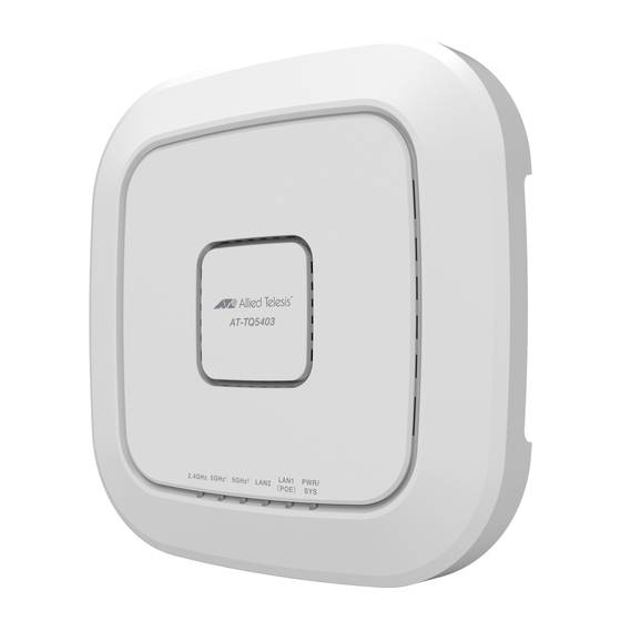
The top view of the AT-TQ5403 model is illustrated in Figure 1. Back Edge Front Edge Figure 1. AT-TQ5403 Model Top View The front edge view of the AT-TQ5403 model is illustrated in Figure 2. Mounting bracket Thumb Screw Hole Figure 2. AT-TQ5403 Model Front Edge View... -
Page 21: Figure 3: At-Tq5403 Model Back Edge View
2018-04-10_Review_Draft AT-TQ5403 Access Point Installation Guide The back edge view of the AT-TQ5403 model is illustrated in Figure 3. Kensington Ethernet DC Power Button Lock Port LAN1-PoE LAN2 Console DC Input DC Input Reset Ports Serial Port Button Jack Jack Figure 3. -
Page 22: Features
2018-04-10_Review_Draft Chapter 1: Product Description Features This section lists the main features of the AT-TQ5403 access point. Hardware The hardware features are as follows: Features Triple radio is supported. The supported frequency ranges may vary depending on the region’s regulations. For example: - USA: 2.4GHz (2412-2462 MHz) -
Page 23: Management Access
LAN Port The AT-TQ5403 access point is equipped with two Ethernet ports - LAN1 and LAN2. The LAN1 port is capable of receiving PoE+ power (PD port) as the primary power or standing by as the backup power source for an external power supply unit. - Page 24 2018-04-10_Review_Draft Chapter 1: Product Description Note The LAN port should be connected to a network device that also adjusts its speed with Auto-Negotiation. If the network device does not support Auto-Negotiation, the LAN port operates at 10 Mbps, which may reduce network performance. Duplex Mode The LAN port can operate in either half- or full-duplex mode at 10/100 Mbps, and full-duplex mode at 1000 Mbps.
-
Page 25: Redundant Power Supply
DC IN jack is the primary power source for the unit. If the power supply unit on the access point fails, power is supplied to the access point via the PoE+ port. Table 1 shows power source for the AT-TQ5403 access point under specific conditions. -
Page 26: Leds
2018-04-10_Review_Draft Chapter 1: Product Description LEDs The LEDs on the access point top panel display the AT-TQ5403 status information. This LED display status information is given in Table 2. Table 2. AT-TQ5403 Access Points LEDs State Description GREEN AT-TQ5403 is powered ON and operating normally. -
Page 27: Cable Specifications
AT-TQ5403 Access Point Installation Guide Cable Specifications The AT-TQ5403 access point is connected to your local area network with Ethernet cables from Ethernet ports LAN1 and LAN2. Refer to “Cable Specifications” on page 48 for the specifications of these cables. - Page 28 2018-04-10_Review_Draft Chapter 1: Product Description...
-
Page 29: Chapter 2: At-Tq5403 Access Point Installation
2018-04-10_Review_Draft Chapter 2 AT-TQ5403 Access Point Installation This chapter describes how to install the AT-TQ5403 access point. It contains the following sections: “Review Safety Precautions” on page 30 “Unpack the AT-TQ5403 Access Point” on page 32 “AT-TQ5403 Access Point Installation Guidelines” on page 33 ... -
Page 30: Review Safety Precautions
2018-04-10_Review_Draft Chapter 2: AT-TQ5403 Access Point Installation Review Safety Precautions Please review the following safety precautions before you begin to install the access point. Note indicates that a translation of the safety statement is available in a PDF document titled Translated Safety Statements on the Allied Telesis website at www.alliedtelesis.com/support. - Page 31 C and a maximum operating altitude of 2000 m or higher, and whose output meets SELV and is rated 12VDC, 2.0A, 2. By Power over Ethernet through an UL Listed ITE. Refer to Table 7, “AT-TQ5403 External Power Supply Specifications” on page 46.
-
Page 32: Unpack The At-Tq5403 Access Point
Name Component AT-TQ5403 Access Point 2 ea RJ-45 Dust Caps 1 ea Mounting Bracket 2 ea Screws for the Chassis (M5 x 8mm, Pan-head) 3. If any item is missing or damaged, contact your Allied Telesis sales representative for assistance. -
Page 33: At-Tq5403 Access Point Installation Guidelines
If the primary power for the access point is to be the external power supply (not provided with the AT-TQ5403 Access Point), ensure that an AC power outlet is within six feet of the planned installation site. (Refer to Table 6 on page 46 for the power supply AC power specifications.) -
Page 34: Install The Access Point
2018-04-10_Review_Draft Chapter 2: AT-TQ5403 Access Point Installation Install the Access Point The AT-TQ5403 access point can be mounted on a table, wall, or hard-surface celling. Before beginning the installation, be sure to Read “Review Safety Precautions” on page 30, and ... -
Page 35: Ceiling Or Wall - Mounting Bracket Installation
1. Go to “Install Ethernet Cables and External DC Power Supply” on page 39. 2. If you choose to install a security cable to the AT-TQ5403, go to “Install Anti-theft Device” on page 41. 3. The installation of your AT-TQ5403 Access Point on the table top surface is now complete. -
Page 36: Figure 5: Attaching The Screws To The Access Point Chassis
2018-04-10_Review_Draft Chapter 2: AT-TQ5403 Access Point Installation Pre-Fitting Mounting Bracket on AT-TQ5403 Access Point To pre-fit the the access point on the mounting bracket, perform the following procedure: 1. Install the two screws (provided) in the bottom side of the access point chassis as shown in Figure 5. -
Page 37: Figure 7: The Access Point With Two Screws Attached
2018-04-10_Review_Draft AT-TQ5403 Access Point Installation Guide 3. Tighten the screws so that they touch the mounting bracket plate and then loosen them by 1/4 turn. Note Adjust the access point chassis screws so they are loose enough to slide into the narrow end of the mounting bracket keyhole. but tight enough to be hold the access point close without rattling against the mounting bracket. -
Page 38: Figure 8: Marking/Pre-Drilling Holes The Mounting Bracket Key-Holes
2018-04-10_Review_Draft Chapter 2: AT-TQ5403 Access Point Installation 2. Using the mounting bracket as a template, mark the two key-hole slots with a pencil in the location and orientation where you want to install the access point. Refer to arrows in Figure 8. -
Page 39: Install Ethernet Cables And External Dc Power Supply
2018-04-10_Review_Draft AT-TQ5403 Access Point Installation Guide 5. Secure the physical position of the mounting bracket by pre-drilling holes through the two existing open bracket mounting holes in the opposite corners from the key-hole slots. Refer to the arrows in Figure 10. -
Page 40: Figure 12: Removing Dust Plug From Lan2 Port
For the AT-TQ5403 PoE+ input power specifications, refer to “PoE Power Requirements” on page 47. 4. Depending on the primary power source for the AT-TQ5403 access point, perform one of the following steps: a. If the access point is to be powered with the PoE+ feature only, then the PoE+ power source is already connected via the Ethernet cable connected to LAN1. -
Page 41: External Ac/Dc Power Adapter Installation
Figure 14. Connecting the External AC/DC Power Adapter Cable 3. Connect the external power supply AC plug to an appropriate AC power source. 4. On the AT-TQ5403 chassis, push the DC Power Button to the “IN” position to turn ON the power supply at the chassis. Note The DC Power Button only controls the ON/OFF power into the DC-IN jack. -
Page 42: Figure 15: Kensington Lock Port Location
Lock Port Figure 15. Kensington Lock Port Location 2. If you are installing your AT-TQ5403 on a table top surface, your unit is now ready for use. 3. If you are installing your AT-TQ5403 on the ceiling or wall installation, go to “Ceiling or Wall - Attach Chassis to Mounting Bracket”... -
Page 43: Ceiling Or Wall - Attach Chassis To Mounting Bracket
2018-04-10_Review_Draft AT-TQ5403 Access Point Installation Guide Ceiling or Wall - Perform this procedure to complete the ceiling or wall installation by attaching the chassis to the mounting bracket. Attach Chassis to Mounting 1. Align and insert the two access point chassis screws into the keyhole Bracket slots of the mounting bracket. -
Page 44: Figure 18: Securely Fasten Chassis To Mounting Bracket With Thumbscrew
3. Tighten the bracket thumbscrew into the front of the chassis until it is securely fastened. Refer to Figure 18. Figure 18. Securely Fasten Chassis to Mounting Bracket with Thumbscrew 4. The ceiling or wall installation is now complete and your AT-TQ5403 Access Point is ready for use. -
Page 45: Appendix A: Technical Specifications
“Cable Specifications” on page 48 “LAN Port Specifications and Pinouts” on page 49 Physical Specifications Table 4. AT-TQ5403 Physical Specifications Parameter Specification Dimensions (W x D x H) 214.74 mm X 214.37 mm X 48 mm (8.45 in. x 8.44 in. x 1.890 in.) Weight (AT-TQ5403 with mounting bracket) .748 Kg (1.65 lbs) -
Page 46: Power Specifications
2018-04-10_Review_Draft Appendix A: Technical Specifications Power Specifications AT-TQ5403 The power specifications for the AT-TQ5403 are given in Table 6. Input Power Specifications Table 6. AT-TQ5403 Input Power Specifications Parameter Specification Rated Input Voltage 12 VDC Maximum Input Current .7 A Average Input Current .52 A... -
Page 47: Poe Power Requirements
2018-04-10_Review_Draft AT-TQ5403 Access Point Installation Guide PoE Power The power requirements of the AT-TQ5403 LAN1 PoE+ port is given in Table 8. Requirements Table 8. AT-TQ5403 PoE+ Power Requirements Parameter Specification AT-TQ5403 25.5 watts PoE Device Classification Class 4 Powered Device... -
Page 48: Cable Specifications
2018-04-10_Review_Draft Appendix A: Technical Specifications Cable Specifications The AT-TQ5403 access point Ethernet cable requirements for the LAN ports are listed in Table 9. Table 9. LAN Port Twisted Pair Cable Requirements 10Mbps 100Mbps 1000Mbps Cable Type PoE+ PoE+ PoE+ Standard TIA/EIA 568-A-compliant... -
Page 49: Lan Port Specifications And Pinouts
2018-04-10_Review_Draft AT-TQ5403 Access Point Installation Guide LAN Port Specifications and Pinouts Port The port specifications are shown in Table 10. Specifications Table 10. LAN Port Specifications Connector Specification Standards - LAN1 and LAN2 IEEE 802.3 (10Base-T) IEEE 802.3u (100Base-TX) IEEE 802.3ab (1000Base-T) PoE standard - LAN1 only IEEE 802.3at (class 4) -
Page 50: Table 12. Mdi-X Pin Signals (10Base-T Or 100Base-Tx)
2018-04-10_Review_Draft Appendix A: Technical Specifications Table 12 lists the pin signals for the MDI-X configuration at 10/100 Mbps. Table 12. MDI-X Pin Signals (10Base-T or 100Base-TX) Signal Table 13 lists the pin signals when the LAN port is operating at 1000 Mbps. -
Page 51: Appendix B: Regulatory Statements
2018-04-10_Review_Draft Appendix B Regulatory Statements This appendix contains the following regulatory statements: “Federal Communication Commission Interference Statement” on page 52 “Europe - EU Declaration of Conformity” on page 54 ... -
Page 52: Federal Communication Commission Interference Statement
2018-04-10_Review_Draft Appendix B: Regulatory Statements Federal Communication Commission Interference Statement This device complies with Part 15 of the FCC Rules. Operation is subject to the following two conditions: (1) This device may not cause harmful interference, and (2) this device must accept any interference received, including interference that may cause undesired operation. - Page 53 2018-04-10_Review_Draft AT-TQ5403 Access Point Installation Guide Radiation Exposure Statement This equipment complies with FCC radiation exposure limits set forth for an uncontrolled environment. This equipment should be installed and operated with minimum distance 20 cm between the radiator & your body.
-
Page 54: Europe - Eu Declaration Of Conformity
2018-04-10_Review_Draft Appendix B: Regulatory Statements Europe - EU Declaration of Conformity Hereby, Allied Telesis, Inc. declares that the radio equipment type [AT-TQ5403] is in compliance with Directive 2014/53/EU. Operating The operating frequencies and maximum transmission power levels for wireless devices operated in the EU are listed below:...
Need help?
Do you have a question about the AT-TQ5403 and is the answer not in the manual?
Questions and answers