
Related Manuals for Allied Telesis AT-TQ6602


Summary of Contents for Allied Telesis AT-TQ6602
- Page 1 AT-TQ6602 Enterprise-class 802.11ax Indoor Wireless Access Point with 2.4GHz and 5GHz Radios Installation Guide 613-002891 Rev. C...
- Page 2 Allied Telesis, Inc. has been advised of, known, or should have known, the...
- Page 3 Federal Communications Commission Interference Statement Declaration of Conformity Manufacturer Name: Allied Telesis Declares that the product: 802.11ax 4x4+4x4 dual radio 2.4G/5G wireless access point Model Number: AT-TQ6602 This device complies with Part 15 of the FCC Rules. Operation is subject to the following two conditions: (1) This device may not cause harmful interference, and (2) this device must accept any interference received, including interference that may cause undesired operation.
- Page 4 European Union Restriction of the Use of Certain Hazardous Substances (RoHS) in Electrical and Electronic Equipment This Allied Telesis RoHS-compliant product conforms to the European Union Restriction of the Use of Certain Hazardous Substances (RoHS) in Electrical and Electronic Equipment. Allied Telesis ensures RoHS conformance by requiring supplier Declarations of Conformity, monitoring incoming materials, and maintaining manufacturing process controls.
- Page 5 TQ6602 Wireless Access Point Installation Guide Wire Communication • IEEE 802.1 • IEEE 802.3 • IEEE 802.3u • IEEE 802.3z • IEEE 802.3ab • IEEE 802.3bz • IEEE 802.3x • IEEE 802.3at • ITU-T G.993.1 Wireless LAN Communication • IEEE 802.11 DSSS •...
- Page 6 Electro Magnetic Susceptibility (EMS) - EN55024 and EN55035 • IEC 61000-4-2 • IEC 61000-4-3 • IEC 61000-4-4 • IEC 61000-4-5 • IEC 61000-4-6 • (IEC 61000-4-8 • IEC 61000-4-11 • IEC 61000-3-2 • IEC 61000-3-3 • 47 CFR Part15, subpart C •...
- Page 7 TQ6602 Wireless Access Point Installation Guide • ICES-003 issue 6 • RSS-102 • RSS-247 issue 2 Japan • JATE • ARIB STD-T66 • ARIB STD-T71 Hong Kong OFCA India WPC Malaysia SIRIM Singapore IMDA TS SRD Complies with IMDA Standards DB102434 Figure 1.
- Page 8 PDF document titled Translated Safety Statements on the Allied Telesis website at www.alliedtelesis.com/library. Remarque: Les consignes de sécurité portant le symbole sont traduites dans plusieurs langues dans le document Translated Safety Statements, disponible à...
-
Page 9: Table Of Contents
Contents Preface ................................15 Safety Symbols Used in this Document ....................16 Contacting Allied Telesis ........................... 17 Chapter 1: Product Description ........................19 Features ..............................20 Hardware Components ..........................23 Ethernet LAN Port ............................25 Power Over Ethernet ........................... 25 Connector Type ........................... 25 Speed .............................. - Page 10 Contents Appendix A: Technical Specifications ......................69 Physical Specifications ..........................69 Environmental Specifications ........................69 Power Specifications ..........................70 Input Power Specifications........................70 External AC/DC Power Adapter Specifications..................70 PoE+ Power Requirements........................70 Cable Specifications ...........................71 LAN Ports Specifications and Pinouts ......................72 Port Specifications ..........................72 Port Pinouts............................72 Appendix B: Regulatory Statements ......................
- Page 11 Figures Figure 1: Singapore IMDA Logo ........................7 Figure 2: Top View ............................23 Figure 3: Front Panel............................24 Figure 4: Rear Panel ............................24 Figure 5: Powering the Access Point with an AC/DC Power Adapter ............. 28 Figure 6: Powering the Access Point with a PoE Power Source..............28 Figure 7: Powering the Access Point with Both an External AC/DC Adapter and a PoE+ Power Source ..
- Page 12 List of Figures...
- Page 13 Tables Table 1. LED Status Information ........................32 Table 2. Physical Specifications ........................69 Table 3. Environmental Specifications ......................69 Table 4. Input Power Specifications ....................... 70 Table 5. External AC/DC Power Adapter Specifications ................70 Table 6. PoE Power Requirements on the Ethernet Port ................70 Table 7.
- Page 14 List of Tables...
-
Page 15: Preface
Preface This guide contains the hardware installation instructions for the indoor IEEE802.11ax TQ6602 Wireless Access Point. The preface contains the following sections: “Safety Symbols Used in this Document” on page 16 “Contacting Allied Telesis” on page 17 ... -
Page 16: Safety Symbols Used In This Document
Preface Safety Symbols Used in this Document This document uses the following conventions. Note Notes provide additional information. Caution Cautions inform you that performing or omitting a specific action may result in equipment damage or loss of data. Warning Warnings inform you that performing or omitting a specific action may result in bodily injury. -
Page 17: Contacting Allied Telesis
Contacting Allied Telesis For assistance with this product, you can contact Allied Telesis technical support by going to the Support & Services section of the Allied Telesis web site at www.alliedtelesis.com/support. You can find links for the following services on this page: 24/7 Online Support —... - Page 18 Preface...
-
Page 19: Chapter 1: Product Description
Chapter 1 Product Description The sections in this chapter describe the hardware components of the 802.11ax TQ6602 Wireless Access Point: “Features” on page 20 “Hardware Components” on page 23 “Ethernet LAN Port” on page 25 “How to Power the Wireless Access Point” on page 28 ... -
Page 20: Features
Chapter 1: Product Description Features Hardware features include: One 2.4GHz radio One 5GHz radio 4x4 MU-MIMO 2.4GHz Internal antennas 4x4 MU-MIMO 5GHz Internal antennas Transmission beamforming One 10/100Mbps/1/2.5/5Gbps Ethernet LAN port with RJ-45 connector IEEE 802.3at PoE+ Class 4 powered device ... - Page 21 TQ6602 Wireless Access Point Installation Guide Dynamic Host Control Protocol (DHCP) client Network Time Protocol (NTP) client System log Syslog client Autonomous Management Framework (AMF) Guest node Security and encryption include: Open system Shared key authentication ...
- Page 22 Chapter 1: Product Description Autonomous Management Framework (AMF) Security or Security Mini (AMF-Sec mini) SNMPv1 and v2c Note For a complete list of features, refer to the TQ6602 Wireless Access Point User Guide or the product’s data sheet.
-
Page 23: Hardware Components
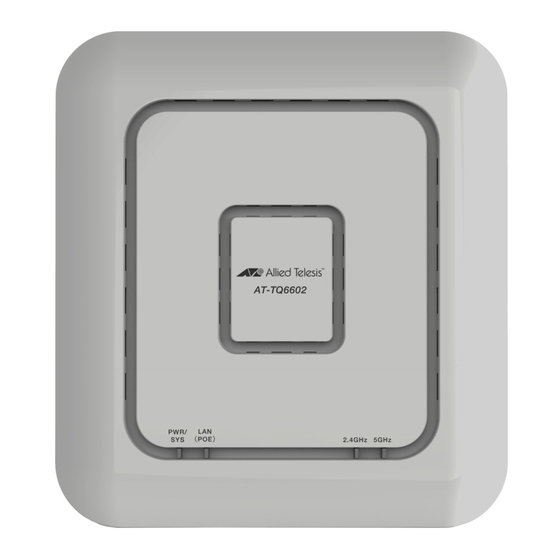
TQ6602 Wireless Access Point Installation Guide Hardware Components The top view of the TQ6602 Wireless Access Point is illustrated in Figure 1. Back Edge Front Edge LAN (PoE) 2.4GHz Radio Port LED PWR/SYS (Power/ 5GHz Radio System) LED Figure 1. Top View... - Page 24 Chapter 1: Product Description The front panel is illustrated in Figure 2. Mounting Bracket Thumbscrew Hole Figure 2. Front Panel The rear panel is shown in Figure 3. Kensington Lock Port Reset Ethernet LAN POWER Button On/Off Button for PoE+ Port DC IN Connector Console DC IN Connector...
-
Page 25: Ethernet Lan Port
PoE power source on the port. A PoE power source can be a PoE router or switch. such as the x320-10GH Switch from Allied Telesis. Electrical power is transmitted to the wireless access point by the power source over the same network cable that carries the network traffic. -
Page 26: Duplex Mode
Chapter 1: Product Description Note You should connect the LAN port to a network device that also supports Auto-Negotiation. The LAN port operates at 10Mbps if it is connected to a network device does not support Auto-Negotiation. This may result in reduced network performance. Duplex Mode The LAN port can operate in either half- or full-duplex mode at 10/100Mbps, and full-duplex mode at higher speeds. -
Page 27: Cable Requirements
TQ6602 Wireless Access Point Installation Guide Cable The minimum cable requirements for the port are listed here. Requirements 10/100 Mbps: Standard TIA/EIA 568-B-compliant Category 3 shielded or unshielded cabling. 1/2.5/5Gbps: Standard TIA/EIA 568-A-compliant Category 5 or TIA/ EIA 568-B-compliant Enhanced Category 5 (Cat 5e) shielded or unshielded cabling. -
Page 28: How To Power The Wireless Access Point
PWRADP-01 (DA-48Z12) Power Adapter from Power Adapter Allied Telesis. Refer to Figure 4. The power adapter is connected to the DC IN connector on the rear panel of the wireless access point. Figure 4. Powering the Access Point with an AC/DC Power Adapter PoE+ Power The wireless access point is a PoE+ powered device, Class 4. -
Page 29: Both Ac/Dc Power Adapter And Poe Power Source
TQ6602 Wireless Access Point Installation Guide Both AC/DC Finally, the device can be powered by both an external AC/DC power adapter and a PoE+ power source. Refer to Figure 6. Power Adapter and PoE Power Source Figure 6. Powering the Access Point with Both an External AC/DC Adapter and a PoE+ Power Source Here are the operating rules of the wireless access point when connected to both an AC/DC power adapter and a PoE+ power source:... -
Page 30: Dc Connector For An External Ac/Dc Power Adapter
DC Connector for an External AC/DC Power Adapter The DC IN connector is for an external AC/DC power adapter, such as the PWRADP-01 Power Adapter from Allied Telesis, shown in Figure 7. Figure 7. PWRADP-01 Power Adapter You can power the wireless access point with either an external power adapter on the DC IN connector or a PoE+ power source on the Ethernet LAN port. -
Page 31: Power On/Off Button
TQ6602 Wireless Access Point Installation Guide POWER On/Off Button The POWER On/Off button on the rear panel powers on or off the DC IN connector for an external AC/DC power adapter. Here are the button settings: In - The DC IN connector is On, allowing power from the AC/DC ... -
Page 32: Leds
Chapter 1: Product Description LEDs The LEDs on the top panel display status information. They are defined in Table 1. Table 1. LED Status Information State Description Solid Green The access point is powered on and operating normally. Solid Red The device is booting up or has encountered a fault condition. - Page 33 TQ6602 Wireless Access Point Installation Guide Table 1. LED Status Information State Description Solid Green The 5GHz Radio2 is enabled. The access point is querying the Slow Blinking wireless network on the 5GHz radio for Green a Smart Connect network of Vista Manager EX and the AWC plug-in.
-
Page 34: Reset Button
Chapter 1: Product Description Reset Button The wireless access point has a Reset button on the rear panel for returning the parameter settings of the device to their default values. You might reset the access point if you want to discard its current configuration or if you forgot the manager password and so cannot manage the device. -
Page 35: Management Tools
You can use SNMPv1 or v2c to view the parameter settings of the devices. The MIB is available from the Allied Telesis web site. For instructions on how to configure the unit for SNMP, refer to the TQ6602 Wireless Access... - Page 36 Chapter 1: Product Description...
-
Page 37: Chapter 2: Beginning The Installation
Chapter 2 Beginning the Installation This chapter contains the following sections: “Reviewing Safety Precautions” on page 38 “Choosing a Site for the Wireless Access Point” on page 41 “Unpacking the Shipping Box” on page 42 Note The non-US models of this product have a country code setting that has to be set during the initial management session of the units. -
Page 38: Reviewing Safety Precautions
Chapter 2: Beginning the Installation Reviewing Safety Precautions Please review the following safety precautions before installing the access point. Important: Safety statements that have the symbol are translated into multiple languages in the Translated Safety Statements document, which is available at www.alliedtelesis.com/library. Remarque: Les consignes de sécurité... - Page 39 TQ6602 Wireless Access Point Installation Guide Warning This equipment shall be installed in a Restricted Access location. Warning FCC Caution: Any changes or modifications not expressly approved by the party responsible for compliance could void the user's authority to operate this equipment. ...
- Page 40 Chapter 2: Beginning the Installation Warning To reduce the risk of electric shock, the PoE port on this product must not connect to cabling that is routed outside the building where this device is located. Warning This equipment is intended for indoor use only. ...
-
Page 41: Choosing A Site For The Wireless Access Point
TQ6602 Wireless Access Point Installation Guide Choosing a Site for the Wireless Access Point Observe these requirements when planning the installation of the wireless access point: The ceiling or wall mounting surface should be of proper material to accommodate the screws and strong enough to support the weight of the wireless access point and cables. -
Page 42: Unpacking The Shipping Box
Chapter 2: Beginning the Installation Unpacking the Shipping Box The contents of the shipping box are shown in Figure 8. Verify and inspect the contents. If any item is missing or damaged, contact your Allied Telesis sales representative for assistance. Note Store the packaging material in a safe location. -
Page 43: Chapter 3: Installing The Wireless Access Point
Chapter 3 Installing the Wireless Access Point This chapter contains the installation procedures for the TQ6602 Wireless Access Point. The procedures are detailed in the following sections: “Installing the Wireless Access Point on a Table” on page 44 “Overview to Installing the Wireless Access Point on a Wall or Ceiling” ... -
Page 44: Installing The Wireless Access Point On A Table
Kensington lock (optional). Note Allied Telesis recommends installing the wall mounting bracket on the bottom panel of the wireless access point when installing the device on a table. The bracket will facilitate airflow through the cooling fins under the device. - Page 45 TQ6602 Wireless Access Point Installation Guide Figure 10. Installing the Bracket Screws The screw collar provides the proper spacing for the mounting bracket beneath the screw head. Refer to Figure 11. Collar Figure 11. Panel Screws 3. Slide the mounting bracket beneath the screws. Refer to Figure 12 on page 46.
- Page 46 Chapter 3: Installing the Wireless Access Point Figure 12. Installing the Mounting Bracket 4. Tighten the bracket retaining screw. Refer to Figure 13. Figure 13. Tightening Bracket Retaining Screw 5. Turn the wireless access point upright on the table. 6. Place the wireless access point at the selected location.
- Page 47 TQ6602 Wireless Access Point Installation Guide 7. Go to one the following procedures “Connecting an Ethernet Cable to the Ethernet LAN Port” on page 56. “Connecting the AC/DC Power Adapter” on page 57. “Installing an Anti-theft Device” on page 61. ...
-
Page 48: Overview To Installing The Wireless Access Point On A Wall Or Ceiling
Chapter 3: Installing the Wireless Access Point Overview to Installing the Wireless Access Point on a Wall or Ceiling You can install the wireless access point on a wall with the front panel pointing to the left, down. or right. Refer to Figure 14. Figure 14. - Page 49 TQ6602 Wireless Access Point Installation Guide Figure 16 shows the device installed on a ceiling. Figure 16. TQ6602 Wireless Access Point on the Ceiling Here are the procedures for installing the wireless access point on a wall or ceiling: “Installing the Mounting Bracket on a Wall or Ceiling” on page 51 ...
- Page 50 Chapter 3: Installing the Wireless Access Point External AC/DC power supply (Optional if using PoE. Required if not using PoE or for redundant power.) Kensington lock (optional and not provided) Note The four Phillips head M4 screws/anchors, the Phillips head screwdriver, pencil, external AC/DC power supply and Kensington lock are not included with the product.
-
Page 51: Installing The Mounting Bracket On A Wall Or Ceiling
TQ6602 Wireless Access Point Installation Guide Installing the Mounting Bracket on a Wall or Ceiling To install the mounting bracket on a wall of ceiling, perform the following procedure: 1. Choose the location and orientation for the access point on the wall or ceiling. - Page 52 Chapter 3: Installing the Wireless Access Point Note For a wooden wall or ceiling, use M4, 25.0 mm flat-head wood screws and anchors, if required. The screws and anchors are not provided with the wireless access point. Figure 18. Installing Two Screws 6.
- Page 53 TQ6602 Wireless Access Point Installation Guide Figure 19. Installing the Wall Mounting Bracket On the Screws 7. Tighten the screws snugly onto the bracket. 8. To secure the mounting bracket, pre-drill holes through the two bracket mounting holes opposite the key-hole slots. Refer to Figure 20. Figure 20.
- Page 54 Chapter 3: Installing the Wireless Access Point 9. Install and tighten two M4 screws (not provided) in the holes prepared in Step 8. Refer to Figure 21. The bracket installation is now complete. Figure 21. Securing the Wall Mounting Bracket 10.
-
Page 55: Installing The Mounting Bracket Screws
TQ6602 Wireless Access Point Installation Guide Installing the Mounting Bracket Screws To install the mounting bracket screws in the wireless access point, perform the following procedure: 1. Place the wireless access point upside down on a table. 2. Install the two screws (provided) fully into the bottom panel of the access point. -
Page 56: Connecting An Ethernet Cable To The Ethernet Lan Port
Chapter 3: Installing the Wireless Access Point Connecting an Ethernet Cable to the Ethernet LAN Port This section contains the procedure for connecting an Ethernet cable to the LAN port. For information on cable specifications, refer to “Cable Requirements” on page 27. Please review the following guidelines before connecting the Ethernet cable: If you are installing the wireless access point on a ceiling or wall, ... -
Page 57: Connecting The Ac/Dc Power Adapter
TQ6602 Wireless Access Point Installation Guide Connecting the AC/DC Power Adapter You can power the wireless access point with PoE on the LAN port or an AC/DC power adapter, or both. Refer to “How to Power the Wireless Access Point” on page 28. To connect a power adapter to the wireless access point, perform the following procedure: 1. - Page 58 Chapter 3: Installing the Wireless Access Point 3. Connect the power adapter’ into an appropriate AC power source. Refer to Figure 26. Figure 26. Connecting the Power Cord on the PWRADP-01 Power Adapter to an AC Source 4. Push the DC Power On/Off Button on the wireless access point to the “IN”...
-
Page 59: Attaching The Wireless Access Point To The Wall Mounting Bracket
TQ6602 Wireless Access Point Installation Guide Attaching the Wireless Access Point to the Wall Mounting Bracket To attach the wireless access point to the wall mounting bracket on the wall or ceiling, perform the following procedure: 1. Align the bottom of the access point over the bracket so that the two screws on the bottom of the device fit into the bracket keyholes. - Page 60 Chapter 3: Installing the Wireless Access Point Figure 29. Seating the Wireless Access Point on the Wall Mounting Bracket 3. Tighten the thumbscrew to secure the wireless access point to the wall mounting bracket. Refer to Figure 30. Figure 30. Tightening the Wall Mounting Bracket Thumbscrew 4.
-
Page 61: Installing An Anti-Theft Device
Note Anti-theft devices are not available from Allied Telesis. Follow the instructions provided with the vendor’s anti-theft device for the installation. Refer to Figure 31 for the Kensington lock port location. - Page 62 Chapter 3: Installing the Wireless Access Point...
-
Page 63: Chapter 4: Managing The Wireless Access Point
Chapter 4 Managing the Wireless Access Point This chapter contains the following sections: “Starting the First Management Session Without a DHCP Server” on page 64 “Starting a Management Session” on page 67 ... -
Page 64: Starting The First Management Session Without A Dhcp Server
Chapter 4: Managing the Wireless Access Point Starting the First Management Session Without a DHCP Server After you install and power on the wireless access point, it queries the subnet on the LAN port for a DHCP server. If a DHCP server responds to its query, the unit uses the IP address the server assigns to it. -
Page 65: Starting The First Management Session With A Direct Connection
TQ6602 Wireless Access Point Installation Guide Starting the First To start the management session with a direct Ethernet connection between your computer and the LAN port on the access point, perform the Management following procedure: Session with a Direct Note Connection If the access point is powered only with PoE, you cannot perform this procedure because it requires a direct connection between your... - Page 66 Chapter 4: Managing the Wireless Access Point 2. Change the IP address on your computer to 192.168.1.n, where n is a number from 1 to 254, but not 230. Refer to the documentation that accompanies your computer for instructions on how to set the IP address.
-
Page 67: Starting A Management Session
TQ6602 Wireless Access Point Installation Guide Starting a Management Session This section explains how to start a management session on the access point from your management workstation, using a web browser. The procedure assumes that the access point has already been assigned an IP address, either manually or from a DHCP server. - Page 68 Chapter 4: Managing the Wireless Access Point Note If you use HTTPS management, your web browser might display a warning message stating that the site certificate is invalid. If this occurs, select an appropriate option to continue to the web site. To avoid the message in future management sessions, make the web site a trusted site in your web browser.
-
Page 69: Appendix A: Technical Specifications
Appendix A Technical Specifications This appendix contains the specifications for the TQ6602 Wireless Access Point in the following sections: “Physical Specifications” “Environmental Specifications” “Power Specifications” on page 70 “Cable Specifications” on page 71 “LAN Ports Specifications and Pinouts” on page 72 ... -
Page 70: Power Specifications
Rated Output Current 0-4.0A Note Allied Telesis recommends the PWRADP-01 (DA-48Z12) AC/DC power adapter. It is UL Listed and fully compatible with the above specifications, while meeting the standards of a separated extra-low voltage (SELV) product. The adapter is sold separately. -
Page 71: Cable Specifications
TQ6602 Wireless Access Point Installation Guide Cable Specifications The minimum cable requirements for the Ethernet port are listed here. 10/100Mbps: Standard TIA/EIA 568-B-compliant Category 3 shielded or unshielded cabling. 1/2.5/5Gbps: Standard TIA/EIA 568-A-compliant Category 5 or TIA/ EIA 568-B-compliant Enhanced Category 5 (Cat 5e) shielded or unshielded cabling. -
Page 72: Lan Ports Specifications And Pinouts
Appendix A: Technical Specifications LAN Ports Specifications and Pinouts Port The access point port specifications are shown in Table 7. Specifications Table 7. LAN Port Specifications Connector Specification Standards IEEE 802.3 (10Base-T) IEEE 802.3u (100Base-TX) IEEE 802.3ab (1000Base-T) IEEE 802.3bz (2.5Base-T IEEE 802.3bz (5Base-T) PoE standard IEEE 802.3at (class tbd) -
Page 73: Table 9. Mdix Pin Signals At 10/100Mbps
TQ6602 Wireless Access Point Installation Guide Table 9 lists the pin signals for ports operating at 10/100Mbps in the MDIX configuration. Table 9. MDIX Pin Signals at 10/100Mbps Signal Table 10 lists the pin signals for LAN ports operating at 1/2.5/5Gbps. Table 10. - Page 74 Appendix A: Technical Specifications...
-
Page 75: Appendix B: Regulatory Statements
Appendix B Regulatory Statements This appendix contains the following regulatory statements: “Federal Communication Commission Interference Statement” on page 76 “Industry Canada Statement” on page 78 “Europe - EU Declaration of Conformity” on page 80 “UK - UKCA Declaration of Conformity” on page 81 ... -
Page 76: Federal Communication Commission Interference Statement
Appendix B: Regulatory Statements Federal Communication Commission Interference Statement This device complies with Part 15 of the FCC Rules. Operation is subject to the following two conditions: (1) This device may not cause harmful interference, and (2) this device must accept any interference received, including interference that may cause undesired operation. - Page 77 TQ6602 Wireless Access Point Installation Guide Radiation Exposure Statement This equipment complies with FCC radiation exposure limits set forth for an uncontrolled environment. This equipment should be installed and operated with minimum distance 20 cm between the radiator & your body.
-
Page 78: Industry Canada Statement
Appendix B: Regulatory Statements Industry Canada Statement This device contains licence-exempt transmitter(s)/receiver(s) that comply with Innovation, Science and Economic Development Canada’s licence- exempt RSS(s). Operation is subject to the following two conditions: (1) This device may not cause interference. (2) This device must accept any interference, including interference that may cause undesired operation of the device. - Page 79 TQ6602 Wireless Access Point Installation Guide Avertissement: Le guide d’utilisation des dispositifs pour réseaux locaux doit inclure des instructions précises sur les restrictions susmentionnées, notamment: (i) les dispositifs fonctionnant dans la bande 5150-5250 MHz sont réservés uniquement pour une utilisation à l’intérieur afin de réduire les risques de brouillage préjudiciable aux systèmes de satellites mobiles utilisant les mêmes canaux;...
-
Page 80: Europe - Eu Declaration Of Conformity
20 cm between Statement the radiator and your body. (NI) Importer Allied Telesis International BV Incheonweg 7, 1437 EK Rozenburg Note Contact Allied Telesis for the EU conformity statement. To contact Allied Telesis, visit our web site at www.alliedtelesis.com/contact. -
Page 81: Uk - Ukca Declaration Of Conformity
TQ6602 Wireless Access Point Installation Guide UK - UKCA Declaration of Conformity Hereby, Allied Telesis declares that the radio equipment type [AT- TQ6602] is in compliance with The Radio Equipment Regulations 2017. Operating The operating frequencies and maximum transmission power... - Page 82 Appendix B: Regulatory Statements...
-
Page 83: Appendix C: Radiation Patterns
Appendix C Radiation Patterns This appendix contains the following sections: “2.4GHz Antenna 1” on page 84 “2.4GHz Antenna 2” on page 87 “2.4GHz Antenna 3” on page 90 “2.4GHz Antenna 4” on page 93 “5GHz Antenna 1” on page 96 ... -
Page 84: Ghz Antenna 1
Appendix C: Radiation Patterns 2.4GHz Antenna 1 X - Z Plane (E-total) - Page 85 TQ6602 Wireless Access Point Installation Guide Y - Z Plane (E-total)
- Page 86 Appendix C: Radiation Patterns X - Y Plane (E-total)
-
Page 87: Ghz Antenna 2
TQ6602 Wireless Access Point Installation Guide 2.4GHz Antenna 2 X - Z Plane (E-total) - Page 88 Appendix C: Radiation Patterns Y - Z Plane (E-total)
- Page 89 TQ6602 Wireless Access Point Installation Guide X - Y Plane (E-total)
-
Page 90: Ghz Antenna 3
Appendix C: Radiation Patterns 2.4GHz Antenna 3 X - Z Plane (E-total) - Page 91 TQ6602 Wireless Access Point Installation Guide Y - Z Plane (E-total)
- Page 92 Appendix C: Radiation Patterns X - Y Plane (E-total)
-
Page 93: Ghz Antenna 4
TQ6602 Wireless Access Point Installation Guide 2.4GHz Antenna 4 X - Z Plane (E-total) - Page 94 Appendix C: Radiation Patterns Y - Z Plane (E-total)
- Page 95 TQ6602 Wireless Access Point Installation Guide X - Y Plane (E-total)
-
Page 96: 5Ghz Antenna 1
Appendix C: Radiation Patterns 5GHz Antenna 1 X - Z Plane (E-total) - Page 97 TQ6602 Wireless Access Point Installation Guide Y - Z Plane (E-total)
- Page 98 Appendix C: Radiation Patterns X - Y Plane (E-total)
-
Page 99: 5Ghz Antenna 2
TQ6602 Wireless Access Point Installation Guide 5GHz Antenna 2 X - Z Plane (E-total) - Page 100 Appendix C: Radiation Patterns Y - Z Plane (E-total)
- Page 101 TQ6602 Wireless Access Point Installation Guide X - Y Plane (E-total)
-
Page 102: 5Ghz Antenna 3
Appendix C: Radiation Patterns 5GHz Antenna 3 X - Z Plane (E-total) - Page 103 TQ6602 Wireless Access Point Installation Guide Y - Z Plane (E-total)
- Page 104 Appendix C: Radiation Patterns X - Y Plane (E-total)
-
Page 105: 5Ghz Antenna 4
TQ6602 Wireless Access Point Installation Guide 5GHz Antenna 4 X - Z Plane (E-total) - Page 106 Appendix C: Radiation Patterns Y - Z Plane (E-total)
- Page 107 TQ6602 Wireless Access Point Installation Guide X - Y Plane (E-total)
- Page 108 Appendix C: Radiation Patterns...
Need help?
Do you have a question about the AT-TQ6602 and is the answer not in the manual?
Questions and answers