Advertisement
Quick Links
Advertisement

Related Manuals for Extreme Flight EXTRA 300-E


Summary of Contents for Extreme Flight EXTRA 300-E
- Page 1 EXTRA 300-E 58” ELECTRIC ARF Instruction Manual ©Copyright 2007 EXTREME FLIGHT RC, Ltd.
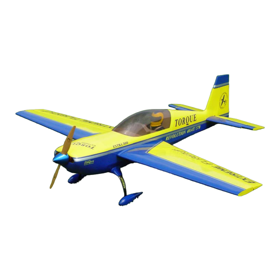
- Page 2 Congratulations on your purchase of the Extreme Flight RC Extra 300 58 inch Electric ARF. This aircraft was designed to provide maximum performance and fun in a great looking, lightweight, easily transported, fully aerobatic ARF aircraft. Using a powerful and efficient brushless outrunner motor and speed controller and a single high discharge 5S1P Lithium Polymer battery (3300-5000 mah), the 58 inch Extra provides unlimited precision and 3D aerobatic performance capability.
- Page 3 Tips for Success-Please read before beginning assembly!!! 1. Read the instruction manual thoroughly before starting assembly. 2. We are very pleased with the level of craftsmanship exhibited by the workers in our factory. However, these are mass produced models. As with any ARF, take a few minutes to go over the model and add CA to high stress areas or any joints that appear to need more glue.
-
Page 4: Wing Assembly
Wing assembly 1. Locate one of the aileron control horns and its mounting base. Remove one of the ailerons from the wing, making sure to keep track of the CA hinges 2. Use a sharp hobby knife to open the slot for the aileron control horn on the bottom of the surface. - Page 5 3. Remove the control horn and use your knife to remove the covering where the base will be glued. Scuff the part of the control horn that will be glued into the aileron slot with sandpaper. Mix up some 30 minute epoxy and apply to the slot and control horn and its base.
- Page 6 5. Place the aileron back on the wing, making sure the hinges are centered between the aileron and wing. Deflect the control surface to full deflection. Use thin CA and a fine tube applicator to apply a couple drops to each hinge. I’ve recently become a convert to the new Mercury adhesives and the M5T thin viscosity formula works great for CA hinges.
- Page 7 6. Remove the covering from the aileron servo bay and install the servo using the manufacturer supplied servo mounting hardware. Position the servo as shown in the picture. You will need to attach a 6 inch servo extension to the aileron servo.
-
Page 8: Fuselage Assembly
7. Locate the threaded aileron pushrods, 2 ball links, 2 screws, 2 nuts and 2 washers that make up the aileron linkage. 8. We highly recommend the use of the Dubro heavy duty control arm set for the Extra, Dubro part number 670 for Futaba, 671 for JR, and 672 for Hitec. For the aileron linkage we will use the 1.14”... - Page 9 11. Before mounting the landing gear, take a minute to wick thin CA into all joints of the landing gear mounting area, both internal and external. Slide the 2 main landing gear legs into position from the side under the retaining lip. Secure the legs with the 4 3mm bolts, using a washer on each bolt.
- Page 10 13. Glue the plywood mounting plate in the center of the wheel pant opening with 30 minute epoxy. Scuff the inside of the wheel pant with sandpaper before gluing. Once dry use a rotary tool to open a slot in the wheel pant using the slot in the ply plate as a guide.
- Page 11 15. Next let’s mount the tailwheel and rudder so we can get the Extra up on its feet, which will make the remainder of assembly much easier. Locate the rudder, 2 cut-down rudder horns and bases, tailwheel wire, aluminum mount, 2 coarse threaded wood screws, tailwheel and 2 small wheel collars.
- Page 12 17. Slide one of the small wheel collars onto the landing gear wire and insert the wire into the aluminum mount. Use a pair of pliers to make a 90 degree bend in the wire as shown. Make sure to bend the wire so it is aligned with the rudder/fuselage.
- Page 13 19. Slide the rudder into position on the rear of the fuselage and use thin CA to secure the rudder hinges. 20. Align the aluminum mounting plate on the rear of the fuselage and secure with the 2 coarse threaded wood screws. You may want to wick a couple drops of CA into the mounting holes before final installation of the screws.
- Page 14 21. Next let’s install the horizontal stabilizer and elevator. Use a sharp hobby knife to remove the covering from the openings in the side of the fuselage to accept the horizontal stab and wing tube. Slide the carbon fiber wing tube into the fiberglass socket in the fuselage and slide the wings into position.
- Page 15 22. Now is the time to make your decision about using one or two servos for elevator actuation. Our suggestion is to use a single HS-5245MG digital servo. If converting the Extra to glow power it is probably wise to use 2 servos to counter the additional weight of the glow engine.
- Page 16 23. Using the same procedure as with the aileron and rudder, install the elevator control horn and base in the bottom of the elevator with 30 minute epoxy. You may need to trim the elevator horn slightly so it doesn’t protrude through the top surface.
- Page 17 25. Next we’ll install the rudder servo and pull-pull system. Use the manufacturer supplied hardware to mount the rudder servo in the tray as shown. Use either the double arm supplied with the servo or the double arm that is part of the Dubro set. 26.
- Page 18 28. Locate one of the brass pull-pull connectors, a ball link, screw, washer and nut. Thread the ball link onto the brass connector. Slide the crimp onto the cable, insert the cable through the hole in the brass connector and back through the crimp.
- Page 19 30. Prepare the motor for mounting. First slide the retaining collar onto the shaft and tighten the set screw. Next mount the bolt-on prop adapter using the 4 long screws included with the Torque Motor. Finally install the radial mount using the 4 beveled head screws.
- Page 20 31. Next mount the motor to the front of the motor box using the remaining 4 bolts, washers and lock nuts. In the photos the motor is mounted before installing the motor box, but this is only for a better view of the mounting procedure. I have found it much easier to mount the motor box to the fuselage first, as outlined previously.
- Page 21 35. Place the canopy/hatch into position and secure with the spring loaded hatch latch. Peel the masking tape back far enough to place the cowl into position. Mount the spinner to the motor to aid in alignment. View the cowl from several perspectives to insure proper alignment and once satisfied lay the tape back into position on the cowl.
- Page 22 37. Apply Velcro to the battery tray as shown (not included) and use a Velcro strap to secure the battery. 38. Below is a picture of our complete radio installation inside the Extra for your reference.
- Page 23 39. Insert the carbon fiber wing tube into the fiberglass socket and slide the wings into position and secure with the nylon thumb screws. The screw is inserted from inside the fuselage and into the blind nut in the wing root. Connect the aileron servo leads to the receiver.
- Page 24 41. Hold the Depron canopy floor up to the bottom of the canopy/hatch and mark the location of the center of the cross member onto the Depron. Cut the floor into 2 pieces at this location. 42. Use foam safe CA to secure the pilot and dash panel into position as shown. The dash panel should overhang the Depron floor by 1/8”...
- Page 25 This concludes the assembly of your Extra!
- Page 26 Set-up and flight tips. CG range for the Extra is from the front of the wing tube to the back of the wing tube. Use the wing tube socket in the wing root to determine the location and transfer this position to the bottom of the wing using a felt tipped marker.
Need help?
Do you have a question about the EXTRA 300-E and is the answer not in the manual?
Questions and answers