
Related Manuals for Adam Equipment WSK 8


Summary of Contents for Adam Equipment WSK 8
- Page 1 Adam Equipment WARRIOR SERIES USER MANUAL (FULL VERSION) SW Ver. 1.24 (P.N. 3136611513 - Revision A, Apr 2014) © Adam Equipment Company 2014...
- Page 2 © Adam Equipment Company 2014...
-
Page 3: Table Of Contents
CONTENTS INTRODUCTION ........................... 2 SPECIFICATIONS ..........................3 INSTALLATION ............................. 4 UNPACKING............................4 LOCATING............................4 SETTING UP THE SCALES ......................5 KEY DESCRIPTIONS ..........................6 DISPLAYS ............................. 8 OPERATION ............................9 ZEROING THE DISPLAY ........................9 TARING ............................. 9 WEIGHING A SAMPLE ........................10 PARTS COUNTING ......................... -
Page 4: Introduction
INTRODUCTION • The Adam Equipment WARRIOR series provide accurate, fast and versatile general purpose type weighing scales with parts counting, percentage weighing and check-weighing functions. • The WARRIOR has LED’s next to the display to indicate when a weight is below the low limit, in between the limits or above the high limit. -
Page 5: Specifications
SPECIFICATIONS WBK 75 WSK 8 WSK 16 WSK 32 WBK 32 WBK 32H Model # WSK 16a WSK 35a WSK 70a WBK 70a WBK70aH 165a Maximum 8000g/16lb 16kg/35lb 32kg/70lb 32kg/70lb 32kg/70lb 75kg/165lb Capacity 0.001kg/ 0.002kg/ 0.002kg/ 0.001kg/ 0.005kg/ Readability 0.5g/0.001lb 0.002lb... -
Page 6: Installation
INSTALLATION UNPACKING The WARRIOR scales have already been adjusted to work with a platform and have been configured for this application. The platform and indicator have been calibrated as a pair and must be used together. LOCATING • The scales should not be placed in a location that will reduce the accuracy. -
Page 7: Setting Up The Scales
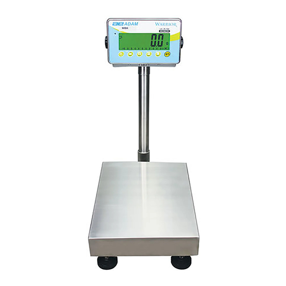
SETTING UP THE SCALES • Remove the Indicator from its box and fix it to the U shaped bracket using the 2 x fixing handles. Take the Indicator and place it onto the pillar ensuring the slack cable is pushed inside. Fix the Indicator to the pillar using the screw provided. -
Page 8: Key Descriptions
KEY DESCRIPTIONS Used to reset the display to zero. Tares the scale. Used to deduct and store the weight currently on the scale if it is not required as part of the final weighing result. A secondary function, is of an “Enter” key used when setting up a value for the Parameters. - Page 9 Selects the Function parameters of the scale. A secondary function (C) is to act as a clear key when clearing an accumulated total. Sends the results to a PC or a Printer using the RS-232 interface. It also adds the value to the accumulation memory if the accumulation function is not automatic.
-
Page 10: Displays
DISPLAYS The LCD display will show a value as well as the unit currently being used. In addition the LED’s above the display will show when a weight is below, inside or above the check-weighing limits. Other symbols will show when a weight has been tared (NET), the scale is at zero and stable, if a value has been stored in memory, or when the animal weighing function has been enabled. -
Page 11: Operation
OPERATION ZEROING THE DISPLAY • You can press the [ 0/T ] key at any time to set the display to zero. This will usually be when the platform is empty. When the zero point is obtained the display will show an indicator for zero. •... -
Page 12: Weighing A Sample
• Press the [ 0/T ] key to tare the scale. The weight is deducted and stored as the tare value leaving zero on the display. The “NET” indicator will be ON and as a product is added only the net weight of the product will be shown. -
Page 13: Parts Counting
PARTS COUNTING If parts counting is enabled, it is possible to count parts using a sample of the parts to determine average piece weight. • Before starting, tare the weight of any container that may be used, leaving the empty container on the scale. Place a known number of samples in the container, if used. -
Page 14: Check-Weighing
• Press the [Pcs/ ] key to return to normal weighing. Press the [Pcs/ ] key again to start counting a different sample. CHECK-WEIGHING Check-weighing is a procedure to cause lamps to come on (and if enabled, an alarm to sound) when the weight on the scale meets or exceeds values stored in memory. -
Page 15: Accumulated Total
ACCUMULATED TOTAL • The scale can be set to accumulate manually by pressing the [Print/M+/Esc] key or automatically when a weight is removed from the scale. See the Section 7.3 for details of setting the Parameter “C3 PRM” and “C4 Aon”. The accumulation function is available when weighing or when counting parts. -
Page 16: Percent Weighing
PERCENT WEIGHING The scale can be set to perform percent weighing. See Section 7.2. The scale will use a mass on the platform as the 100% reference weight. If the platform is empty (or the scale is tared) then the user can input a reference weight using the keypad. - Page 17 • The number of decimal points will depend on the weight used in comparison to the capacity of the system. A smaller weight will show only “100%” while a larger weight might show “100.00%”. • If the scale was showing zero weight when entering this function, then the user must manually enter the weight to be set as 100% as described below.
-
Page 18: Animal (Dynamic) Weighing
ANIMAL (DYNAMIC) WEIGHING The scale can be set to animal (dynamic) weighing for weighing any items that are unstable or may move. See Section 7.4. The scale will use a special filter to minimise the effects of any movement while the moving animal or unstable samples are on the scale. - Page 19 ANIMAL WEIGHING PROCEDURE • With the platform empty the display will show zero weight. Place containers or blankets onto the platform and press the [ 0/T ] key to zero the display. The scale may go into the animal (dynamic) weighing procedure when the items are placed on the scale but will return to showing zero when the [ 0/T...
-
Page 20: User Parameters
USER PARAMETERS Pressing the [Func/C] key during normal operation allows the user to access the parameters for customizing the scale. The parameters are split into 4 groups:- 1. Check weighing parameters, 2. Percent and Animal Weighing Functions 3. RS-232 parameters 4. -
Page 21: Percent Weighing And Animal Weighing
Parameter Description Options Default setting F1 Lo Set Low limit. Use the [Unit/ ] key 000000 and [Pcs/ ] key to set the values of the lower limit. When set press the 0/T ] key to store the value and go to F2 F2 Hi Set High limit. -
Page 22: Rs-232 Parameters
Parameter Description Options Default setting P1 PCt This parameter allows the None Enabled user to enter the Percent always weighing Function. See Section 6.7. P2 Ani Enter the Animal Weighing Set the filter value. Enabled mode of operation, See Always section 6.8 RS-232 PARAMETERS •... -
Page 23: Scale Parameters
AC oFF C5 Ln EnGLi (English) EnGLi Select Language FrEnCH (French) GErmAn (German) SPAn (Spanish) C6 UId Set User ID To be entered 000000 manually C7 Sid Set Scale ID To be entered 000000 manually Scale will perform the following, depending on the Accumulation and Print Settings: AC on AC Off CCUMULATION... - Page 24 This group of parameters is used to control the operation of the scale. Parameter Description Options Default setting S1 Un Enable or disable weighing units, will not Grams allow to disable all units, at least one has to be enabled. Parts lb:oz counting can be N (Newtons)
-
Page 25: Battery Operation
BATTERY OPERATION • The scales can be operated from the battery if desired. The battery life can be up to 70 hours depending on the load cells and how the backlight is used. • A battery symbol is shown on the display which indicates the current charge of the battery, 3 bars means fully charged. -
Page 26: Rs-232 Interface
RS-232 INTERFACE The Warrior indicator is supplied with bi-directional RS-232 interface as standard. The scale, when connected to a printer or computer outputs the weight with the selected weighing unit through the RS-232 interface. Specifications: RS-232 output of weighing data ASCII code 600 - 19200 Baud (user selectable, default 9600) 8 data bits... - Page 27 Data Format - Normal Output: <cr><lf> <cr><lf> Date 12/09/2006 <cr><lf> Time 14:56:27 <cr><lf> <cr><lf> If ID is zero, it is left blank Scale ID 123456 <cr><lf> User ID 234567 <cr><lf> <cr><lf> Net Wt. (or Gross Wt.) Net Wt 1.234 Kg <cr><lf>...
- Page 28 Data Format - Memory Recall Output: <cr><lf> Date 12/09/2006 <cr><lf> Time 14:56:27 <cr><lf> <cr><lf> Scale ID 123456 <cr><lf> User ID 234567 <cr><lf> <cr><lf> ------------------<cr><lf> TOTAL <cr><lf> 1.234 Kg <cr><lf> <cr><lf> 10 pcs <cr><lf> ------------------<cr><lf> <cr><lf> Data Format - Continuous Output, Normal weighing: ST or US for STable or UnStable, ST,GROSS 1.234 Kg <cr><lf>...
- Page 29 Number of Stck. Piezas items counted Number of weighing Anzhl Num. added to subtotals Total weight and count Total Total Gesamt Total printed Print date Date Date Datum Fecha Print time Time Heure Zeit Hora Scale ID Scale ID Bal ID Waagen ID Bal ID number...
-
Page 30: Input Commands Format
INPUT COMMANDS FORMAT The scale can be controlled with the following commands. Press the [Enter] key of the PC after each command. T<cr><lf> Tares the scale to display the net weight. This is the same as pressing [ 0/T ... -
Page 31: Relay Interface
The circuit to control the relays requires an external voltage compatible with the relays used. Contact Adam Equipment or your supplier for a relay interface that is compatible with the relay drivers, however other interfaces can be used as long as the following conditions apply. - Page 32 Connections to the relay drivers: Connections are made to the PCB, Connector P1. The connector is a spring activated type, simply press on the top of the connector and insert the wire. Do not exceed the safe limits of voltage or current of 24VDC or 15ma per output.
-
Page 33: Calibration
11.0 CALIBRATION The scale can be calibrated using the following procedure. To enter this procedure it is necessary to use Func 4 which is accessible using the [Func/C] key as described in section 7.4 in the full manual, or by using the passcode access as described in section 12.0. -
Page 34: Service Parameters
12.0 SERVICE PARAMETERS The scales will allow entry to the parameters if the [Tare] key is pressed during the power on cycle. The passwords work as above. In this case the display will show the passcode request screen, “ P - - - - “ . To continue enter a passcode as described below. -
Page 35: Using The Service Parameters
The parameters available are: “F4 Int” Initial Zero Range “F5 rEZ” Re-Zero range “F6 SCS” Successive Tare Enable “F7 Cnt” Display the A/D counts “F8 Zem” Zero Mode “F9 Lvd” Low voltage detection “FA AZn” Auto Zero Range “Fb FPS” User Function Password The description of the parameters is shown below USING THE SERVICE PARAMETERS... - Page 36 This parameter allows you to view the A/D counts from the internal A/D converter. This can be an aid to service. Press the [ 0/T ] key to return to the PARAMETER menu. Press the [Print/M+/Esc] key to return to weighing. Typical value at zero is 30,000-90,000 (approx.).
- Page 37 F9 –LOW VOLTAGE DETECTION This parameter allows detection of low voltage when the battery wears down. ] key when “F9 LVd” is shown. To enter this parameter, press the [ 0/T The display will show if the LVD Mode is set to on or oFF. Press the [Pcs/ ] key to change the value.
-
Page 38: Error Codes
13.0 ERROR CODES ERROR DESCRIPTION SUGGESTIONS CODES - -oL - - Over-range Remove weight from the scale. If the problem persists contact your dealer or Adam Equipment for assistance. Err 1 Time Setting Enter time using correct format and reasonable Error values. -
Page 39: Replacement Parts And Accessories
14.0 REPLACEMENT PARTS AND ACCESSORIES If you need to order any spare parts and accessories, contact your supplier or Adam Equipment. A partial list of such items is as follows:- • • Power Supply Module Printer, printer paper etc. •... -
Page 40: Service Information
15.0 SERVICE INFORMATION This manual covers the details of operation. If you have a problem with the scale that is not directly addressed by this manual then contact your supplier for assistance. In order to provide further assistance, the supplier will need the following information which should be kept ready: A. - Page 41 Page 39...
-
Page 42: Warranty Information
16.0 WARRANTY INFORMATION Adam Equipment offers Limited Warranty (Parts and Labour) for the components which fail due to defects in materials or workmanship. Warranty starts from the date of delivery. During the warranty period, should any repairs be necessary, the purchaser must inform their supplier, or Adam Equipment Company. -
Page 43: Fcc Compliance
Shielded interconnect cables must be employed with this equipment to insure compliance with the pertinent RF emission limits governing this device. Changes or modifications not expressly approved by Adam Equipment could void the user's authority to operate the equipment. WEEE COMPLIANCE... - Page 44 © Copyright by Adam Equipment Co. All rights reserved. No part of this publication may be reprinted or translated in any form or by any means without the prior permission of Adam Equipment. Adam Equipment reserves the right to make changes to the technology, features, specifications and design of the equipment without notice.
Need help?
Do you have a question about the WSK 8 and is the answer not in the manual?
Questions and answers