Table of Contents
Advertisement
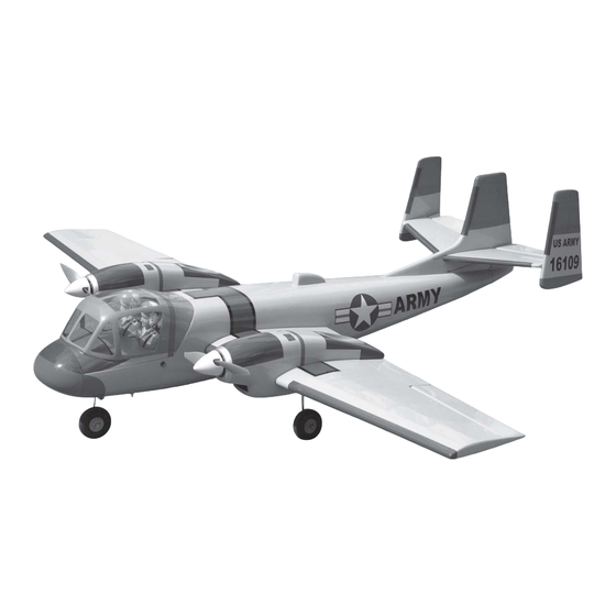
Instruction Manual book
SPECIFICATION
Wingspan :
Length
Weight
Radio
Servo
Parts Listing Required (not included).
Electric Motor (02 motors) : AXI 2814/12.
Speed Control (02pcs) : 40A.
Battery: 3 CELLS-LI-POL Y
1 1.1 v-5.000 mA.h-20C.
Propeller (02pcs) :10 x 6
1,450 mm
:
1,200 mm
:
2.3 kg
:
04 channels.
:
06 servos.
ITEM CODE: BH49.
57.09 in.
47.24 in.
5.06 Lbs.
Made in Vietnam.
Advertisement
Table of Contents

Subscribe to Our Youtube Channel
Related Manuals for Black Horse Model OV-1 MOHAWK


Summary of Contents for Black Horse Model OV-1 MOHAWK
- Page 1 Instruction Manual book ITEM CODE: BH49. SPECIFICATION Wingspan : 1,450 mm 57.09 in. Length 1,200 mm 47.24 in. Weight 2.3 kg 5.06 Lbs. Radio 04 channels.
-
Page 2: Parts List
OV - 1 MOHAWK. INSTRUCTION MANUAL. This instruction manual is designed to help you build a great flying aeroplane. Please read this manual thoroughly before starting assembly of your OV- 1 MOHAWK. Use the parts listing below to identify all parts. WARNING. -
Page 3: Safety Precaution
OV-1 MOHAWK. INSTRUCTION MANUAL. Caution: this model is not a toy! SAFETY PRECAUTION. If you are a beginner to this type of powered + This is not a toy model, please ask an experienced model flyer + Be sure that no other flyers are using your for help and support. - Page 4 OV - 1 MOHAWK. INSTRUCTION MANUAL. INSTALLING THE AILERON - FLAP SERVO CONTROL HORN. INSTALLING THE AILERON - SERVO CON- C/A glue. TROL HORN. 1) Install the rubber grommets and brass eyelets onto the aileron servo. 2) Install the metal connector onto servo arm.
- Page 5 OV-1 MOHAWK. INSTRUCTION MANUAL. Remove the covering. Aileron. Micro control connector. 5) Attach the micro control connector to the servo arms. Be sure to use the lock tie but it could free rotation. 4) Install the aileron servo as same as picture.
- Page 6 OV - 1 MOHAWK. INSTRUCTION MANUAL. Slot aileron Aileron Bottom side. Flap 6) Using a ruler & pen to draw a straight C/A glue. line as below picture. Remover covering. Insert aileron control horn to the aileron. Pushrod wire Secure.
- Page 7 OV-1 MOHAWK. INSTRUCTION MANUAL. Bottom side Finishing. Pushrod wire INSTALLING FLAP SERVO-CONTROL HORN. Flap control horn. Remove covering. Flap Remove covering. C/A glue. Flap...
- Page 8 OV - 1 MOHAWK. INSTRUCTION MANUAL. INSTALLING ELECTRIC MOTOR. See pictures below: Motor mount wood: Flap control horn 3x 10mm. Aileron Flap Top side of the left wing halft. Bottom side of the left t wing halft. Aileron control horn Repeat the procedure for the other wing half.
- Page 9 OV-1 MOHAWK. INSTRUCTION MANUAL. Secure.
- Page 10 OV - 1 MOHAWK. INSTRUCTION MANUAL.
- Page 11 OV-1 MOHAWK. INSTRUCTION MANUAL. Top side of left haft wing Remark Wing second slot : far from the first slot 75mm to the wing tip side. Tracing a line with your finger and using a ENGINE NACELLE INTALLATION. modeling knife remove a (3mm) wide strip to...
- Page 12 OV - 1 MOHAWK. INSTRUCTION MANUAL. Wng slot Mark the line Wng slot Mark the line Finishing C/A glue. Installing Nacelle bottom side of left haft wing...
-
Page 13: Instruction Manual
OV-1 MOHAWK. INSTRUCTION MANUAL. Remove covering the second slot C/A glue Mark the line Wng slot Mark the line Wng slot Remove covering the first slot... - Page 14 OV - 1 MOHAWK. INSTRUCTION MANUAL. C/A glue Secure Bottom side Push down Push Repeat the procedure for the other right haft wing.
-
Page 15: Installing The Spinner
OV-1 MOHAWK. INSTRUCTION MANUAL. INSTALLING THE SPINNER. Bottom side of the left wing halft. 2x10mm Top side of the left wing halft. MAIN GEAR INSTALATION. 3x12mm Repeat the procedure for the other spinner. - Page 16 OV - 1 MOHAWK. INSTRUCTION MANUAL. Remove covering Wing slot...
-
Page 17: Installing The Nose Gear
OV-1 MOHAWK. INSTRUCTION MANUAL. INSTALLING THE NOSE GEAR. Attach the pushrod wire to the steering Bottom arm. -
Page 18: Servo Installation
OV - 1 MOHAWK. INSTRUCTION MANUAL. Install the nose gear and secure it. Nose gear servo Secure. Secure SERVO INSTALLATION. 1) Install the rubber grommets and brass eyelets onto the elevator servo and nose gear servo. 2) Install the metal connector onto servo arm. -
Page 19: Horizontal Stabilizer Installa- Tion
OV-1 MOHAWK. INSTRUCTION MANUAL. HORIZONTAL STABILIZER INSTALLA- TION. Bottom side. PEN . 1) Using a modeling knife, cut away the covering from the fuselage for the stabilizer and remove it. Remove covering. Bottom side. 4) Remove the stabilizer. Using the lines... -
Page 20: Elevator Control Horn Installation
OV - 1 MOHAWK. INSTRUCTION MANUAL. 5) When you are sure that everything is aligned correctly, mix up a generous amount C/A glue. of 30 minute epoxy. Apply a thin layer to the top and bottom of the stabilizer mounting area and to the stabilizer mounting platform sides in the fuselage. -
Page 21: Elevator Pushrod Installation
OV-1 MOHAWK. INSTRUCTION MANUAL. Elevator Elevator pushrod pushrod Elevator Elevator slot slot Elevator control horn. C/A glue. ELEVATOR PUSHROD INSTALLATION. Secure Elevator pushrod install as same as pic- ture below. Elevator pushrod Bend and cut... -
Page 22: Vertical Stabilizer Installation
OV - 1 MOHAWK. INSTRUCTION MANUAL. VERTICAL STABILIZER INSTALLATION. Nose gear pushrod Rudder Left rudder Right rudder Put the rudder in the fuse lage as same as picture below. Mark the shape of the vertical on the left and right side into the stabilizer using a felt- tipped pen. - Page 23 OV-1 MOHAWK. INSTRUCTION MANUAL. Epoxy glue. Bottom side of elevator. Put the vertical stabilizer back in place. Using a triangle, check to ensure that the Push. vertical stabilizer is aligned 90 degree to the horizontal stabilizer. Vertical Stabilizer. Horizontal 90º...
- Page 24 OV - 1 MOHAWK. INSTRUCTION MANUAL. Bottom side of the elevator. Rudder on the right Push. Pen. Top side of the elevator. Right side. Top side of the elevator. Remove covering 90 degrees Using 30 minute epoxy to attach the fin to the stabilizer.
- Page 25 OV-1 MOHAWK. INSTRUCTION MANUAL. Check to mark sure the wing and stabi- lizer are paralell. If they are not, lightly sand C/A glue. the opening in the fuselage for the stabilizer until the stabilizer is paralell to the wing. ATTACHMENT WING-FUSELAGE.
-
Page 26: Installing The Receiver And Battery
OV - 1 MOHAWK. INSTRUCTION MANUAL. INSTALLING THE RECEIVER AND BATTERY. 1. Plug the servo leads and the switch wing bolt lead into the receiver . You may want to plug an aileron extension into the receiver to make plugging in the aileron servo lead easier when you are installing the wing . - Page 27 OV-1 MOHAWK. INSTRUCTION MANUAL. Tie wrap. Bolt Secure FASTENING THE FUSELAGE HATCH. Fibreglass cover. Top side of fuselage C/A glue. Fuselage top hatch.
-
Page 28: Control Throws
be fully extended and not coiled up inside the fuselage. 85mm 6) Properly balance the propeller. We wish you many safe and enjoyable flights with your OV-1 MOHAWK.
Need help?
Do you have a question about the OV-1 MOHAWK and is the answer not in the manual?
Questions and answers