Black Horse Model GILMORE Instruction Manual Book
Hide thumbs
Also See for GILMORE:
- Instruction manual book (32 pages) ,
- Instruction manual book (30 pages)

Subscribe to Our Youtube Channel
Related Manuals for Black Horse Model GILMORE


Summary of Contents for Black Horse Model GILMORE
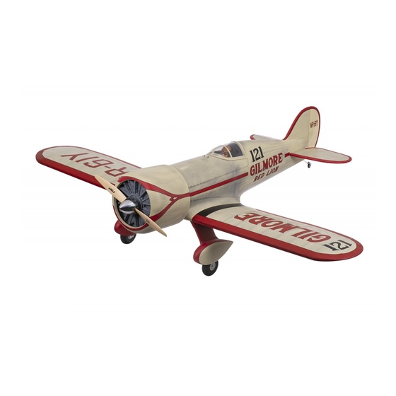
- Page 1 Instruction Manual book SPECIFICATION Wingspan : 2,150 mm 84.65 in. Length 1,640 mm 64.57 in. Weight 5.9kg 12.98 Lbs. Radio 06 channels. Servo 06 servos. Engine 45 - 50CC Gas. Made in Vietnam.
-
Page 2: Parts List
GILMORE Instruction Manual This instruction manual is designed to help you build a great flying aeroplane. Please read this manual thoroughly before starting assembly of your GILMORE. Use the parts listing below to identify all parts. WARNING Please be aware that this aeroplane is not a toy and if assembled or used incorrectly it is capable of causing injury to people or property. -
Page 3: Safety Precaution
GULMORE. INSTRUCTION MANUAL INSTALLING THE AILERON SERVOS. SAFETY PRECAUTION. + This is not a toy 1. Install the rubber grommets and brass + Be sure that no other flyers are using your eyelets onto the aileron servo. radio frequency. + Do not smoke near fuel + Store fuel in a cool, dry place, away from children and pets. - Page 4 GILMORE Instruction Manual C/A glue. Bottom side. Bottom side. Bottom side. Secure 2. Using a modeling knife, remove the cov- ering servo tray. Servo tray. 4. Using the thread as a guide and using masking tape, tape the servo lead to the end of the thread: carefully pull the thread out.
- Page 5 GULMORE. INSTRUCTION MANUAL 5. Instal servo tray with aileron servo into INSTALLING THE AILERON CONTROL HORN. the wing as same as picture below. Servo tray. Nilon control clasp. M3 lock nut. 3 x 40mm. 2 x 10 mm. Secure Control horn of Aileron Remove covering.
-
Page 6: Installing The Aileron Linkages
GILMORE Instruction Manual Repeat the procedure for the other wing half. INSTALLING THE AILERON LINKAGES. Installing the aileron linkages as pictures below. M3 lock nut... - Page 7 GULMORE. INSTRUCTION MANUAL MAIN GEAR INSTALATION. PARTS REQUIRED Mark point 3x15mm 3x15mm Remove covering Secure Mark point...
- Page 8 GILMORE Instruction Manual Secure...
- Page 9 GULMORE. INSTRUCTION MANUAL Secure Secure Secure Mart line...
- Page 10 GILMORE Instruction Manual Remove covering C/A glue Epoxy glue C/A glue Epoxy glue...
-
Page 11: Installing The Stopper Assembly
GULMORE. INSTRUCTION MANUAL Repeat the procedure for the other wing half. FUEL TANK. INSTALLING THE STOPPER ASSEMBLY 1) The stopper has been pre-assembled at the factory. 2) Using a modeling knife, cut one length of silicon fuel line (the length of silicon fuel line is calculated by how the weighted clunk should rest about 8mm away from the rear of the tank and move freely inside the tank). - Page 12 GILMORE Instruction Manual Blow through one of the lines to ensure the fuel lines have not become kinked inside the fuel tank compartment. Air should flow through easily. 9) To secure the fuel tank in place, apply a bead of silicon sealer to the forward area of...
-
Page 13: Installing The Engine
GULMORE. INSTRUCTION MANUAL Right side Secure Tie wrap. Left side INSTALLING THE ENGINE. Tie wrap. Locate the long piece of wire used for the throttle pushrod. One end of the wire has been pre-bend in to a “Z” bend at the factory. This “Z”... - Page 14 GILMORE Instruction Manual Right side. Throttle servo COWLING. INSTALLING THE THROTTLE PUSHROD. 1. Install one adjustable metal connector through the third hole out from the center of one servo arm, enlarge the hole in the servo arm using a 2mm drill bit to accommodate the servo connector.
- Page 15 GULMORE. INSTRUCTION MANUAL 4. Install the muffler and muffler extension onto the engine and make the cutout in the cowl for muffler clearance. Connect the fuel and pressure lines to the carburetor, muffler and fuel filler valve. Left side Trim and cut Right side 3 x 12mm Bottom side...
-
Page 16: Horizontal Stabilizer
GILMORE Instruction Manual Right side HORIZONTAL STABILIZER. ELEVATOR INSTALLATION. 1. Install the rubber grommets and brass collets into the elevator servo. Test fit the servo into the servo tray. 2. Mount the servo to the tray using the mounting screws provided with your radio sys- tem. - Page 17 GULMORE. INSTRUCTION MANUAL center line C/A glue C/A glue 3. Mark the shape of the vertical on the left and right sides onto the horizontal stabilizer using a felt-tip pen C/A glue Mark line 4. Remove the stabilizer. Using the lines you just drew as a guide, carefully remove the See pictures below: covering from between them using a modeling...
-
Page 18: Elevator Control Horn Installa- Tion
GILMORE Instruction Manual Top side. C/A glue Check to mark sure the wing and stabi- lizer are paralell. If they are not, lightly sand the opening in the fuselage for the stabilizer until the stabilizer is paralell to the wing. - Page 19 GULMORE. INSTRUCTION MANUAL Remove covering Bottom side. Elevator Elevator control horn control horn...
-
Page 20: Elevator Pushrod Installation
GILMORE Instruction Manual ELEVATOR PUSHROD INSTALLATION. Elevator pushrod install as same as the way of aileron pushrod. Elevator Elevator pushrod pushrod Bottom side. Remove covering Top side. Elevator servo Elevator pushrod Elevator pushrod... -
Page 21: Vertical Installation
GULMORE. INSTRUCTION MANUAL VERTICAL INSTALLATION. 1. Put the rudder into the fuselage as same as picture below. 2. Mark the shape of the vertical on the left and right side of the rudder on to the horizon- tal stabilizer using a felt-tip pen. 3. - Page 22 GILMORE Instruction Manual 4. Now, remove the rudder and using a modeling knife, carefully cut just inside the marked lines and remove the film of the rud- der. Just as you did with the horizontal stabi- lizer, make sure you only press hard enough to cut the film, not the balsa rudder.
-
Page 23: Rudder Pushrod Installation
GULMORE. INSTRUCTION MANUAL RUDDER PUSHROD INSTALLATION. 1. Rudder pushrod install as same as the way of aileron control horn. 2. Rudder push - pull system install as same as picture below. C/A glue Remove covering C/A glue RUDDER CONTROL HORN INSTALLA- TION. - Page 24 GILMORE Instruction Manual Rudder servo C/A glue Rudder control horn Elevator Elevator pushrod pushrod Rudder Rudder cable cable...
-
Page 25: Mounting The Tail Wheel Bracket
GULMORE. INSTRUCTION MANUAL Rudder servo MOUNTING THE TAIL WHEEL BRACKET. 1. Set the tail wheel assembly in place on the plywood plate. The pivot point of the tail wheel wire should be even with the rud- der hinge line and the tail wheel bracket should be centered on the plywood plate. -
Page 26: Installing The Switch
GILMORE Instruction Manual switch INSTALLING THE RECEIVER AND BATTERY. 1. Plug the servo leads and the switch lead into the receiver. You may want to plug an aileron extension into the receiver to make Secure plugging in the aileron servo lead easier when you are installing the wing . -
Page 27: Wing Attachment
GULMORE. INSTRUCTION MANUAL Drill a hole 3mm diameter Receiver 3 x 40mm Secure WING ATTACHMENT. Locate the aluminium wing dihedral brace. *** Test fit the aluminium tube dihedral brace into each wing haft. The brace should slide in easily. If not, use 220 grit sand around the edges and ends of the brace until it fits prop- erly. - Page 28 GILMORE Instruction Manual Right side Left side WING ATTACHMENT. See picture wing attach to fuselage. Wing bolt. Installing the fuselage hatch as same as pic- ture below. Wing bolt.
- Page 29 GULMORE. INSTRUCTION MANUAL Insert and secure. BALANCING. 1) It is critical that your airplane be bal- anced correctly. Improper balance will cause your plane to lose control and crash. THE CENTER OF GRAVITY IS LOCATED 130MM BACK FROM THE LEADING EDGE OF THE WING.
-
Page 30: Pre-Flight Check
6) Properly balance the propeller. 3) Check to be sure the control surfaces We wish you many safe and enjoyable move in the correct directions. flights with your GILMORE. Ailerons : 15mm up 15mm down Elevator : 15mm up 15mm down...
Need help?
Do you have a question about the GILMORE and is the answer not in the manual?
Questions and answers