Table of Contents
Advertisement
Quick Links
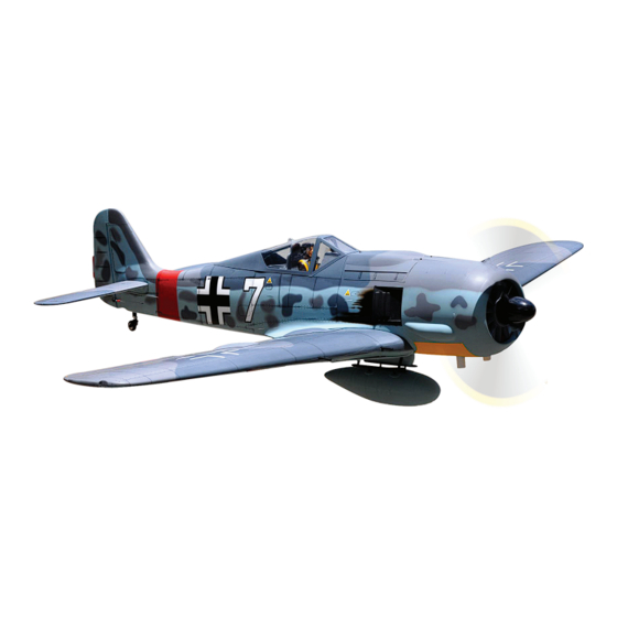
Focke Wulf 190A
INCLUDED AIR RETRACT LANDING GEAR WITH OLEO STRUTS.
ALL BALSA - PLY WOOD CONSTRUCTION.
COVERED IN A HEAT-SHRINK FILM WITH PRINTED.
95% ALMOST READY TO FLY
SPECIFICATION:
- Wingspan: 2,600mm (102.4in).
- Length: 2,230mm (87.8in).
- Weight: 15kg (33lbs).
- Wing area: 117 dm².
- Wing loading: 128.2 g/dm².
- Wing type: Naca Airfoil.
- Servo mount: 42mm x 21mm.
- Gear type: Air retract gear with oleo
struts for main gear and air retract
gear with oleo struts for tail gear
(included).
- Spinner size: Plastic 95mm
Instruction Manual Book
Parts listing required (not included):
- Radio: 07 channels.
- Servo: 9 standard high torque servos.
- Engine: 120 cc gas.
- Motor: Brushless outrunner 185 KV.
- Propeller motor: 28 x 10.
- Propeller engine: 27 x 10.
Recommended motor and battery set up (not
included):
- Electric Motor: BOOST 180.
- Battery: 12S LIPO 44,4V 6,000mAh.
- Speed control: 120A. HV.
- Receiver battery: 6.0V 2400-2600mAh(2 Packs).
Item code: BH178
Glow and EP
Made in Vietnam.
Advertisement
Table of Contents

Related Manuals for Black Horse Model Focke Wulf 190A


Summary of Contents for Black Horse Model Focke Wulf 190A
- Page 1 Instruction Manual Book Item code: BH178 Focke Wulf 190A Glow and EP INCLUDED AIR RETRACT LANDING GEAR WITH OLEO STRUTS. ALL BALSA - PLY WOOD CONSTRUCTION. COVERED IN A HEAT-SHRINK FILM WITH PRINTED. 95% ALMOST READY TO FLY SPECIFICATION: Parts listing required (not included): - Wingspan: 2,600mm (102.4in).
-
Page 2: Table Of Contents
Thank you for purchasing Black Horse Model products. With over 18 years experience in production and fly testing, Black Horse Model is committed to bring the best quality products and good service to customers. Along with a team of creative engineers and skilled workers, we will always accompany with customers by our great experiences, fully enthusiasm... -
Page 3: Warranty
In that Black Horse Model has no control over the final assembly or material used for final assembly, SUGGESTION Black Horse Model is not responsible for loss of use , or other incidental or consequential damages. To avoid scratching your new airplane, do not... -
Page 4: Covering Tools
FOCKE WULF Item code: BH178 Instruction Manual FLIGHT WARNINGS ADHESIVES AND REQUIRED TOOLS When ready to fly, first extend the transmitter aerial. Thin CA Switch on the transmitter. 30-minute epoxy Switch on the receiver. 6-minute epoxy Check that the wings are correctly fitted to the Threadlocker thread locking cement fuselage. - Page 5 FOCKE WULF Item code: BH178 Instruction Manual • Officially designated AMA Air Show Teams (AST) are authorized to use devices and practices as defined within the Team AMA Program Document. (AMA Document #718.) (j) Not operate a turbine-powered aircraft, unless in compliance with the AMA turbine regulations. (AMA Document #510-A.) 3.
-
Page 6: Parts Listing (Not Included)
FOCKE WULF Item code: BH178 Instruction Manual PARTS LISTING (NOT INCLUDED). Servo extension leads....pcs. Engine: 120cc gas ..220mm 2 pcs. Motor: BOOST 180 ..620mm 2 pcs. LiPo. 12S - 44,4V - 6,000mAh. 2 Packs Servos Size: ( 39.9 x 20.1 x 38.1)mm. Torque: 6V (11.3kg/cm), 7.4V (12.9kg/cm)..9pcs ESC: 120A..1 pcs. - Page 7 FOCKE WULF Item code: BH178 Instruction Manual : Fuselage. Door strut gear (13a, 13b). (19a: 3 way connector, : Wing panel ( 2a, 2b ). 19b: 4 way connector) Retract main gear (14a, 14b). Air line sets. : Horizontal stabilizer ( 3a, 3b ). Tail gear set.
-
Page 8: Preparations
FOCKE WULF Item code: BH178 Instruction Manual INSTALLING THE FLAP CONTROL HORNS AND LINKAGES Horn Ball link 3x15mm Tp Screw 3mm Hex Nut - - - 8 - - - - - - - - - - - 8 - - - - 2 - - - - 4 Horn 3x12mm Cap Screw... -
Page 9: Installing The Ailerons And Flaps
FOCKE WULF Item code: BH178 Instruction Manual INSTALLING THE AILERONS AND FLAPS 44mm Pinned hinge - - - - - - - - - - - - - 12 67mm Pinned hinge - - - - - - - - - - - - - 8 Bottom Side 44mm Pinned hinge 67mm Pinned hinge... -
Page 10: Installing The Ailerons And Flap Servos
FOCKE WULF Item code: BH178 Instruction Manual Right wing Bottom Side Left wing Bottom Side INSTALLING THE AILERON AND FLAP SERVO Using the thread as a guide and using masking tape, tape the servo lead to the end of the thread: carefully pull the thread out. - Page 11 FOCKE WULF Item code: BH178 Instruction Manual For Flap For Flap For Flap Screw 3mm Cap Screw 3mm Flat Washer Hex Nut For Flap For Flap Cut off shaded portion Drill holes using the stated. Assemble left and right sides the same way. carefully.
- Page 12 FOCKE WULF Item code: BH178 Instruction Manual 3mm Flat Washer Aileron Aileron Ball Link 3mm Hex Nut 3x12mm Cap Screw Aileron Aileron mm Tp Screw Aileron 2x10mm Tp Screw 1.5mm Cut off shaded portion Drill holes using the stated. carefully. (in this case 2mm The number of times Assemble left and right...
- Page 13 FOCKE WULF Item code: BH178 Instruction Manual For Aileron For Flaps 2x10mm Tp Screw Bottom Side Tie the string Pull out servo cord with string. Aileron Aileron Aileron Aileron 3x15mm Tp Screw Horn Horn 3x12mm Cap Screw Aileron Aileron C . A Bottom Side Assemble left and right sides the same way.
-
Page 14: Installing The Air Retractable Landing Gear
FOCKE WULF Item code: BH178 Instruction Manual INSTALLING THE AIR RETRACTABLE LANDING GEAR 6mm Collar 4mm Spring Washer 6x60mm Socket Head 2x10mm Tp Screw Cap Screw - - - - - - - - - - - - 2 - - - - 8 - - - - 8 - - - - 2 3x6mm Button Head... - Page 15 FOCKE WULF Item code: BH178 Instruction Manual 6mm Collar 6mm Flat Washer 6x60mm Socket Head Cap Screw 4x20mm Socket Head Cap Screw 4mm Flat Washer Bottom Side Assemble left and right sides the same way. Drill holes using the stated. (in this case 2mm...
- Page 16 FOCKE WULF Item code: BH178 Instruction Manual Bottom Side 2x10mm Tp Screw Bottom Side Bottom Side Assemble left and right sides the same way.
- Page 17 FOCKE WULF Item code: BH178 Instruction Manual 67mm 94mm 94mm Bottom Side 3x6mm Button Head Cap Screw Bottom Side Bottom Side Assemble left and right sides the same way.
-
Page 18: Horizontal Stabilizer Installation
FOCKE WULF Item code: BH178 Instruction Manual - - - - - - - - 4 Bottom Side Bottom Side Apply instant glue (C.A glue, super glue). Assemble left and right sides the same way. HORIZONTAL STABILIZER INSTALLATION When you are sure that everything is aligned 1. - Page 19 FOCKE WULF Item code: BH178 Instruction Manual Make certain plane is aligned accurately per the diagram. A mis-aligned plane can fly Warning! erraticaliy and cause accidents. Pinned Hinge Aluminium Tube 12mm - - - 1 Fuselage Top Side 374mm Assemble left and right Aluminium sides the same way.
- Page 20 FOCKE WULF Item code: BH178 Instruction Manual Fuselage Top Side...
-
Page 21: Rudder Installation
FOCKE WULF Item code: BH178 Instruction Manual 4x16mm Button Head 4x16mm Button Head 4mm Flat Washer Cap Screw Cap Screw - - - - - - - - - - - 4 4mm Flat Washer - - - - - - - - - - - 4 Fuselage Bottom Side 4mm Flat Washer 4x16mm Button Head... -
Page 22: Installing The Elevator Linkages
FOCKE WULF Item code: BH178 Instruction Manual Cut off shaded portion Apply epoxy glue INSTALLING THE ELEVATOR LINKAGES Repeat these step as installing the aileron linkages. Aluminum ball Horn - - - - - - - 2 - - - - - - - - - - 4 - - - - - - - - - - 4 3x12mm Cap Screw 2.6 x1200mm Push rod... - Page 23 FOCKE WULF Item code: BH178 Instruction Manual Fuselage Bottom Side 3x15mm Tp Screw Horn 3x12mm Cap Screw The number of times Assemble left and right Cut off shaded portion the same way Assembly sides the same way carefully. (in this case twice).
- Page 24 FOCKE WULF Item code: BH178 Instruction Manual 3x12mm Button 3x12mm Button Head Cap Screw Head Cap Screw 3mm Flat Washer 3mm Flat Washer 3mm Hex Nut 3mm Hex Nut Fuselage Top Side Elevator Servo Elevator Servo...
-
Page 25: Installing The Rudder Linkages
FOCKE WULF Item code: BH178 Instruction Manual INSTALLING THE RUDDER LINKAGES Aluminum ball Horn - - - - - 1 - - - - - - - - - - - - 2 3x12mm Cap Screw - - - - - - - - - - - - 4 3x12mm Cap Screw Horn - - - - - - 2... - Page 26 FOCKE WULF Item code: BH178 Instruction Manual 3x12mm Button Head Cap Screw 3mm Flat Washer 3mm Hex Nut 3x12mm Button Head Cap Screw 3mm Flat Washer Servo Rudder Ball Link 3mm Connector 3mm Hex Nut Cab link Hex Nut Cut off excess. Must be purchased Cut off shaded portion separately!
-
Page 27: Installing The Tail Gear
FOCKE WULF Item code: BH178 Instruction Manual Fuselage Top Side Rudder servo INSTALLING THE TAIL GEAR 1400mm Cable rod Aluminum ball 3x12mm Button Head Cap Screw - - - - - - - - - - - - 2 - - - - - 2 - - - - - 2 - - - - - - - - - - - - 4 4x12mm Socket Head... - Page 28 FOCKE WULF Item code: BH178 Instruction Manual Crimp Crimp Cable rod 4mm Spring Washer 4x12mm Socket Head Cap Screw...
- Page 29 FOCKE WULF Item code: BH178 Instruction Manual Fuselage Bottom Side Fuselage Bottom Side...
- Page 30 FOCKE WULF Item code: BH178 Instruction Manual Fuselage Bottom Side Close / Open 3x12mm Button Head Cap Screw 3mm Flat Washer Servo tail gear Ball Link 3mm Connector 3mm Hex Nut Cab link Hex Nut...
-
Page 31: Secure The Wing To The Fuselage
FOCKE WULF Item code: BH178 Instruction Manual Fuselage Top Side Tail Gear Tail Gear SECURE THE WING TO THE FUSELAGE 32mm Aluminium tube. Attach the wings to the fuselage and secure the 995mm wing panels. 32mm 665mm... - Page 32 FOCKE WULF Item code: BH178 Instruction Manual Fuselage Top Side 665mm Aluminium Tube Fuselage Top Side 995mm Aluminium Tube Fuselage Top Side...
- Page 33 FOCKE WULF Item code: BH178 Instruction Manual Fuselage Top Side Fuselage Top Side 4x15mm Screw 4x15mm Screw...
-
Page 34: Installing The Engine
FOCKE WULF Item code: BH178 Instruction Manual INSTALLING THE ENGINE M6 Blind Nut 16x50mm Aluminium 6mm Flat Washer mm Flat Washer - - - - - - - 4 - - - - - - - - 4 - - - - - - - 4 - - - - - - - 4 550mm Pushrod wire 6x80mm Socket Head... - Page 35 FOCKE WULF Item code: BH178 Instruction Manual Zip tie Fuselage Top Side 550mm Pushrod wire...
-
Page 36: Installing The Throttle
FOCKE WULF Item code: BH178 Instruction Manual INSTALLING THE THROTTLE Connector 1. Plug the throttle servo into the receiver and turn on the radio system. Check to ensure that the throttle servo output shaft is moving in the correct direction. When the throttle stick is moved forward from idle to full throttle, the throttle barrel should also open and close using this motion. -
Page 37: Installing The Stopper
FOCKE WULF Item code: BH178 Instruction Manual INSTALLING THE STOPPER Cut off shaded portion... -
Page 38: Installing The Fuel Tank
FOCKE WULF Item code: BH178 Instruction Manual INSTALLING THE FUEL TANK 5. When satisfied with the alignment of the stopper assembly tighten the 3mm x 20mm machine screw until the rubber stopper expands and 1. Using a modeling knife, cut one length of silicon seals the tank opening. -
Page 39: Installing The
FOCKE WULF Item code: BH178 Instruction Manual INSTALLING THE ..Fuselage Top Side Assemble left and right Apply instant glue sides the same way. (C.A glue, super glue). -
Page 40: Mounting The Cowl
FOCKE WULF Item code: BH178 Instruction Manual MOUNTING THE COWL 4. While holding the cowl firmly in position, drill 1. Remove the muffler and needle valve assembly four 1,6mm pilot holes through both the cowl from the engine. Slide the fiberglass cowl over the and the side edges of the firewall. - Page 41 FOCKE WULF Item code: BH178 Instruction Manual Fuselage Top Side Plastic Apply epoxy glue.
- Page 42 FOCKE WULF Item code: BH178 Instruction Manual Fuselage Top Side 3x12mm Tp Screw Fuselage Top Side...
- Page 43 FOCKE WULF Item code: BH178 Instruction Manual 3x12mm Tp Screw Fuselage Top Side C . A 3x12mm Tp Screw 3x12mm Tp Screw C . A 3x12mm Tp Screw Drill holes using the stated. (in this case 2.5mm 2.5mm Apply instant glue (C.A glue, super glue).
-
Page 44: Installing Valve Control
FOCKE WULF Item code: BH178 Instruction Manual INSTALLING VALVE CONTROL Valve control Valve one way Connector Air tank 3 way conector 4 way conector Air line sets CLEANING THE VALVE Must be purchased separately! - Page 45 FOCKE WULF Item code: BH178 Instruction Manual...
-
Page 46: Installing The Receiver And Battery
FOCKE WULF Item code: BH178 Instruction Manual Fuselage Top Side Valve control servo Zip tie Air tank Air tank Zip tie INSTALLING THE RECEIVER AND BATTERY INSTALLING THE SWITCH 1. Plug the servo leads and the switch lead into the 1. - Page 47 FOCKE WULF Item code: BH178 Instruction Manual mm Tp Screw Fuselage Top Side Plywood mm Tp Screw Switch Switch Foam Pad Tape Receiver Battery Battery Must be purchased separately!
-
Page 48: Installing Cockpit Fuselage
FOCKE WULF Item code: BH178 Instruction Manual INSTALLING COCKPIT FUSELAGE Position the canopy so the rear frame on the canopy is aligned with the rear edge of the cock- pit opening. Use canopy glue to secure the canopy to the canopy hatch. Use low-tack tape to hold the canopy in position until the glue fully cures. - Page 49 FOCKE WULF Item code: BH178 Instruction Manual Fuselage Top Side Fuselage Top Side Open / Close Apply epoxy glue.
-
Page 50: Installing The Propeller
FOCKE WULF Item code: BH178 Instruction Manual Open / Close Fuselage Top Side Adhesive tape. INSTALLING THE PROPELLER 3x12mm Socket Head Cap Screw - - - - - - - - - - - - 4 95mm Fuselage Top Side Drill holes using the stated. - Page 51 FOCKE WULF Item code: BH178 Instruction Manual Fuselage Top Side 3x12mm Socket Head Cap Screw Fuselage Top Side...
-
Page 52: Installing Keine Bombe
FOCKE WULF Item code: BH178 Instruction Manual INSTALLING KEINE BOMBE! Keine Bombe! Aluminum - - - - 4 Pinned hinge - - - - - - - - 4 4x16mm Socket Head Cap Screw Plastic - - - - - - - - 3 4x12mm Socket Head Cap Screw - - - - - - - - 4... - Page 53 FOCKE WULF Item code: BH178 Instruction Manual Apply epoxy glue.
- Page 54 FOCKE WULF Item code: BH178 Instruction Manual 4x16mm Socket Head Cap Screw 4mm Spring Washer Fuselage Bottom Side...
- Page 55 FOCKE WULF Item code: BH178 Instruction Manual 4mm Spring Washer 4x12mm Socket Head Cap Screw Fuselage Bottom Side...
-
Page 56: Balancing
FOCKE WULF Item code: BH178 Instruction Manual LATERAL BALANCE BALANCING 1. It is critical that your airplane be balanced correctly. After you have balanced a plane on the C.G. Improper balance will cause your plane to lose You should laterally balance it. Doing this will control and crash. - Page 57 FOCKE WULF Item code: BH178 Instruction Manual Cut off excess. In order to obtain the CG specified, reposition the receiver and other equipment. If not obtain the CG specified, add a weight and Do not fly before confirming the adjust. correct location of the CG.
-
Page 58: Control Throws
FOCKE WULF Item code: BH178 Instruction Manual FLIGHT PREPARATION PRE FLIGHT CHECK CONTROL THROWS 1) Completely charge your transmitter and We highly recommend setting up a plane using receiver batteries before your first day of flying. the control throws listed. 2) The control throws should be measured at the 2) Check every bolt and every glue joint in your widest point of each control surface. -
Page 59: For Your Radio Installation Basic Connection For Airplane And Adjustment Of Servos
FOCKE WULF Item code: BH178 Instruction Manual 25mm Flap Control FOR YOUR RADIO INSTALLATION BASIC CONNECTION FOR AIRPLANE AND ADJUSTMENT OF SERVOS Example of connection For more information, refer to radio system instruction manual. Follow instruction manual of Engine and Battery. Aileron Servo Aileron Aileron Servo... -
Page 60: Main Gear Dimensional Detail
FOCKE WULF Item code: BH178 Instruction Manual MAIN GEAR DIMENSIONAL DETAIL 70mm 158mm 54mm 32mm 45mm 6.1mm hole TAIL GEAR DIMENSIONAL DETAIL 314mm 23mm 47mm... -
Page 61: Decoration
FOCKE WULF Item code: BH178 Instruction Manual DECORATION Hier aufbocken Reifendruck 5 atü Hier aufbocken... -
Page 62: Exploded View
FOCKE WULF Item code: BH178 Instruction Manual... - Page 63 I/C FLYING WARNINGS Always operate in open areas, away from fly near power lines,aerials or AL WAYS adjust the engine from behind NEVER factories, hospitals, schools, buildings other dangerous areas including airports, the propeller, and do not allow any part of and houses etc.
- Page 64 I/C FLYING GUIDELINES Operate the control sticks on the ALWAYS land the model INTO When ready to fly, first extend transmitter and check that the the wind, this ensures that the the transmitter aerial. control surfaces move freely and in model lands at the slowest possible the CORRECT directions.
Need help?
Do you have a question about the Focke Wulf 190A and is the answer not in the manual?
Questions and answers