Table of Contents
Advertisement
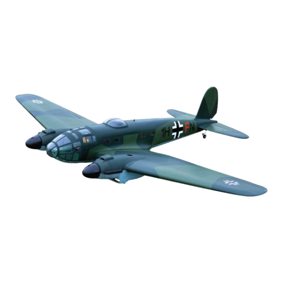
Instruction Manual Book
Glow and EP
ALL BALSA - PLY WOOD CONSTRUCTION.
COVERED IN A HEAT-SHRINK FILM WITH PRINTED.
95% ALMOST READY TO FLY
SPECIFICATION:
- Wingspan: 1,750 mm (68.90 in).
- Length: 1,280 mm (50.39 in).
- Weight: 4.2 - 4.5 kg (9.25 - 9.92 lbs).
- Wing area: 48.9dm
2
.
- Wing loading: 92.04g/dm
- Servo mount: size (29 x 13 x 30) mm.
- Wing type: Naca airfoil.
- Gear type: Electric retract gear, size:
81 x 44 x 29 mm (not included).
Oleo struts (included).
- Spinner size: Plastic 75mm.
Parts listing required (not included):
- Radio: 06 channels.
- Servo: 07 - 9 servos.
- Engine: 25 - 2 stroke (2 pcs).
- Motor: Brushless outrunner 400 - 700W, 800-1000KV (2pcs).
- Propeller: Suit with your engine.
2
.
Recommended Motor
and Battery set up (not included):
- Motor: Admiral GP2
- Lipo cell: 3 cell LIPO 11.1V 3,250 - 3,700 mAh
(2 packs).
- ESC: 65A (2 pcs).
- Receiver battery: 6V/ 800-1200mAh NiMH.
Item code: BH143
Made in Vietnam
Advertisement
Table of Contents

Subscribe to Our Youtube Channel
Related Manuals for Black Horse Model HE-111


Summary of Contents for Black Horse Model HE-111
- Page 1 Instruction Manual Book Item code: BH143 Glow and EP ALL BALSA - PLY WOOD CONSTRUCTION. COVERED IN A HEAT-SHRINK FILM WITH PRINTED. 95% ALMOST READY TO FLY SPECIFICATION: Parts listing required (not included): - Wingspan: 1,750 mm (68.90 in). - Radio: 06 channels. - Length: 1,280 mm (50.39 in).
-
Page 2: Table Of Contents
Thank you for purchasing Black Horse Model products. With over 18 years experience in production and fly testing, Black Horse Model is committed to bring the best quality products and good service to customers. Along with a team of creative engineers and skilled workers, we will always accompany with customers by our great experiences, fully enthusiasm... -
Page 3: Warranty
In that Black Horse Model has no control over the final assembly or material used for final assembly, SUGGESTION Black Horse Model is not responsible for loss of use , or other incidental or consequential damages. To avoid scratching your new airplane, do not... -
Page 4: Covering Tools
Instruction manual HE-111 Item code: BH143 ADHESIVES AND REQUIRED TOOLS FLIGHT WARNINGS When ready to fly, first extend the transmitter aerial. Thin CA Switch on the transmitter. 30-minute epoxy Switch on the receiver. 6-minute epoxy Check that the wings are correctly fitted to the Threadlocker thread locking cement fuselage. - Page 5 Instruction manual HE-111 Item code: BH143 • Officially designated AMA Air Show Teams (AST) are authorized to use devices and practices as defined within the Team AMA Program Document. (AMA Document #718.) (j) Not operate a turbine-powered aircraft, unless in compliance with the AMA turbine regulations. (AMA Document #510-A.)
-
Page 6: Parts Listing (Not Included)
Instruction manual HE-111 Item code: BH143 PARTS LISTING (NOT INCLUDED) Servo extension leads. 330mm ..2 pcs. Engine: .25 ci glow... 2pcs 330mm ..pcs. 190mm ..2 pcs. Propeller. Suit with your engine. LiPo. 3S - 3000- 4000mAh. 12AWG 200 C 450mm .. - Page 7 Instruction manual HE-111 Item code: BH143 : Fuselage : Wing panel ( 2a, 2b ). : Canopy fuselage ( 3a: front canopy, 3b: main canopy, 3c: top canopy, 3d: Bottom canopy, 3e: Pilot). : Horizontal stabilizer ( 4a, 4b ).
-
Page 8: Installing The Ailerons And Flaps
Instruction manual HE-111 Item code: BH143 INSTALLING THE AILERONS AND FLAPS Bottom view Aileron Flap 1) Test fit the aileron to the wing with the hinges. If the hinges dont’t remain centered, stick a pin through the middle of the hinge to hold it in position. - Page 9 Instruction manual HE-111 Item code: BH143 Bottom view For Aileron Servo For Flap Servo Flap Aileron and Aileron ap servos. approx.16mm 2x10mm TP Screw For Flap For Flap. 1.5mm For Aileron For Aileron. TP Screw 1.5mm 1.5mm 2x10mm TP Screw...
-
Page 10: Installing The Ailerons And Flaps Linkages
Instruction manual HE-111 Item code: BH143 Bottom view INSTALLING THE AILERONS AND FLAPS LINKAGES 1) Working with the aileron linkage for now, thread one With the aileron and aileron servo centered, carefully nylon clevis onto one of the threaded wires. - Page 11 Instruction manual HE-111 Item code: BH143 Nylon Clevis Pushrod Horn Pushrod Flaslink 1.7x8mm Mark the spot to attach Bend 90 Bottom view Left Right...
-
Page 12: Installing The Main Gear
Instruction manual HE-111 Item code: BH143 INSTALLING THE MAIN GEAR There are two options: MAIN LANDING GEAR ELECTRIC LANDING GEAR RETRACTS ELECTRIC GEAR DIMENSIONAL DETAIL (mm) XWAVE RM400-90 REACT SHOWN 3x15mm Tp Screw 3 x 10mm Wheel Collar ELECTRIC NOT INCLUDED. -
Page 13: Main Gear Struts
Instruction manual HE-111 Item code: BH143 OPTION 1: MAIN GAER STRUTS Drill holes using the stated. (in this case 1.5mm 2.5mm Apply instant glue (C.A glue, super glue). C . A Assemble left and right sides the same way. 3 x 15mm Screw C . -
Page 14: Electric Gear Retracts
Instruction manual HE-111 Item code: BH143 OPTION 2: ELECTRIC GEAR RETRACTS Screw 3 x 15mm C . A Bottom view Screw the gear in position Bottom view... -
Page 15: Horizontal Stabilizer Installation
Instruction manual HE-111 HE-111 Item code: BH143 Item code: BH143 HORIZONTAL STABILIZER INSTALLATION 1. Using a modeling knife, cut away the covering When you are sure that everything is aligned from the fuselage for the stabilizer and remove it. correctly, mix up a generous amount of 30 minute epoxy. - Page 16 Instruction manual HE-111 Item code: BH143 Top view A = A’ B = B’ B’ A’...
-
Page 17: Installing The Tail Gear And Rudder
Instruction manual HE-111 Item code: BH143 INSTALLING THE TAIL GEAR AND RUDDER 5mm Wheel Collar 4x4mm Setscrew - - - - - - - - - - - 1 - - - - - - - - 1 2mm Nylon Collar... -
Page 18: Installing The Elevator Pushrod
Instruction manual HE-111 Item code: BH143 3 x 12 mm Bottom view Take off the main wing after put a rudder. 90 Degree Apply epoxy glue. Pay close attention here. INSTALLATION THE ELEVATOR PUSHROD Locate one nylon servo arm, and using wire 1. - Page 19 Instruction manual HE-111 Item code: BH143 Apply epoxy glue. Horn Push rod The number of times 2.5mm the same way Assembly Nylon clevis (in this case twice). Cut off excess. Cut off shaded portion carefully. Horn Pay close attention here.
-
Page 20: Installing The Rudder Linkages
Instruction manual HE-111 Item code: BH143 Elevator Pushrod Elevator Servo INSTALLATION THE RUDDER LINKAGES approx.16mm... - Page 21 Instruction manual HE-111 Item code: BH143 Nylon Clevis - - - - - 1 Nylon Clevis Push rod 800mm Push rod - - - - - 1 Flaslink - - - - - 1 - - - - - 1 Horn 1.7x8mm Cap Screw...
-
Page 22: Installing The Engine Mount
Instruction manual HE-111 Item code: BH143 Top view Rudder Pushrod Rudder Servo INSTALLATION THE ENGINE MOUNT There are two options: ELECTRIC MOTOR ENGINE MOUNT OPTION 1: INSTALLING THE ELECTRIC MOTOR (EP VERSION) 4mm Flat Washer M3 Blind Nut - - - - - - - - - 8... - Page 23 Instruction manual HE-111 Item code: BH143 Top view 4 x 16mm 10 x 40mm 4 x 60mm Top view Assemble left and right sides the same way.
-
Page 24: Secure The Wing To The Fuselage
Instruction manual HE-111 Item code: BH143 Top view Assemble left and right sides the same way. SECURE THE WING TO THE FULSELAGE 512mm 19 Aluminium - - - - - 1 ●Attack the wings to the joiner tube and secure the wing panels to the fuse lage. - Page 25 Instruction manual HE-111 Item code: BH143 Top view 4x15mm Top view...
-
Page 26: Installing The Receiver And Battery
Instruction manual HE-111 Item code: BH143 INSTALLING THE RECEIVER AND BATTERY INSTALLING THE SWITCH 1. Plug the servo leads and the switch lead into the 1. The switch should be mounted on the fuselage receiver. You may want to plug an aileron... -
Page 27: Mounting The Cowl
Instruction manual HE-111 Item code: BH143 MOUNTING THE COWL 3 x 12mm TP Screw - - - - - - - - - - 8 Plastic Part - - - - - 4 Top view When rotating clock wise, change the connection of 2 wires. - Page 28 Instruction manual HE-111 Item code: BH143 3 x 12mm Tp Screw Top view C . A C . A 205mm C . A Bottom view 3 x 12mm Tp Screw C . A C . A C . A Apply instant glue (C.A glue, super glue).
-
Page 29: Installation The Stopper
Instruction manual HE-111 Item code: BH143 INSTALLATION THE STOPPER... -
Page 30: Installation The Fuel Tank
Instruction manual HE-111 Item code: BH143 INSTALLING THE FUEL TANK INSTALLATION THE FUEL TANK 6) When satisfied with the alignment of the stopper 1) Using a modeling knife, cut one length of silicon assembly tighten the 3mm x 20mm machine screw... - Page 31 Instruction manual HE-111 Item code: BH143 Clunks 3 x 12mm Tp Screw - - - - - - - - - - 1 - - - - - - 4 - - - - - - - - - - 1...
-
Page 32: Installation The Engine
Instruction manual HE-111 Item code: BH143 INSTALLATION THE ENGINE 4mm Flat Washer - - - - - - - - - - 8 4mm Spring Washer - - - - - - - - - - 8 3 x 20mm Cap Screw... - Page 33 Instruction manual HE-111 Item code: BH143 Top view 3x20mm Cap Screw Assemble left and right sides the same way. Top view...
-
Page 34: Installing The Throttle
Instruction manual HE-111 Item code: BH143 INSTALLING THE THROTTLE 1. Install one adjustable metal connector 3. Slide the adjustable metal connector / servo through the third hole out from the center of one arm assembly over the plain end of the pushrod servo arm, enlarge the hole in the servo arm wire. -
Page 35: Mounting The Cowl
Instruction manual HE-111 Item code: BH143 MOUNTING THE COWL 4. While holding the cowl firmly in position, drill 1. Remove the muffler and needle valve assembly four 1,6mm pilot holes through both the cowl from the engine. Slide the fiberglass cowl over the and the side edges of the firewall. - Page 36 Instruction manual HE-111 Item code: BH143 Top view 3 x 12mm Tp Screw C . A Top view...
- Page 37 Instruction manual HE-111 Item code: BH143 Top view 3 x 12mm Tp Screw C . A Bottom view C . A...
-
Page 38: Installing Canopy Fuselage
Instruction manual HE-111 Item code: BH143 Bottom view INSTALLING CANOPY FUSELAGE Position the canopy so the rear frame on the canopy is aligned with the rear edge of the cockpit opening. Use canopy glue to secure the canopy to the canopy hatch. Use low-tack tape to hold the canopy in position until the glue fully cures. - Page 39 Instruction manual HE-111 Item code: BH143 Top view Adhesive tape. Top view...
- Page 40 Instruction manual HE-111 Item code: BH143 Top view Open / Close Bottom view Bottom view...
-
Page 41: Installing The Spinner
Instruction manual HE-111 Item code: BH143 Bottom view Adhesive tape. Bottom view INSTALLING THE SPINNER Install the spinner back-plate, propeller and spinner cone. The propeller should not touch any part of the spinner cone. If it dose, use a sharp modeling knife and carefully trim away the spinner cone where the propeller comes in contact with it. - Page 42 Instruction manual HE-111 Item code: BH143 Top view 3 x12 mm Tp Screw Must be purchased separately!
-
Page 43: Balancing
Instruction manual HE-111 Item code: BH143 BALANCING If one side of the wing fall, that side is heavier than the opposite. Add small amounts of lead weight to the bottom side of the lighter wing half's It is critical that your airplane be balanced wing tip. -
Page 44: For Your Radio Installation Basic Connection For Airplane And Adjustment Of Servos
Instruction manual HE-111 Item code: BH143 FOR YOUR RADIO INSTALLATION BASIC CONNECTION FOR AIRPLANE AND ADJUSTMENT OF SERVOS ● For more information, refer to radio system instruction manual. Example of connection ● Follow instruction manual of Engine and Battery. Aileron Servo... -
Page 45: Main Gear Dimensional Detail
Instruction manual HE-111 Item code: BH143 MAIN GEAR DIMENSIONAL DETAIL MAIN GEAR STRUTS LANDING GEAR MOUNT 31mm 44mm TAIL GEAR DIMENSIONAL DETAIL 37mm 21mm 1.5mm hold 5.1mm hold 25mm 2mm hold 26mm... -
Page 46: Decoration
Instruction manual HE-111 Item code: BH143 DECORATION DECORATION < Top view > < Bottom view > < Side view > Left < Side view > Right... - Page 48 I/C FLYING WARNING Always operate in open areas, away from NEVER fly near power lines,aerials or ALWAYS adjust the engine from behind factories, hospitals, schools, buildings other dangerous areas including airports, the propeller, and do not allow any part and houses etc. NEVER fly your aircraft motorways etc.
- Page 49 I/C FLYING GUIDE Operate the control sticks on the ALWAYS land the model INTO When ready to fly, first extend transmitter and check that the th e wind , this en su res tha t th e the transmitter aerial. control surfaces move freely and in model lands at the slowest possible the CORRECT directions.
Need help?
Do you have a question about the HE-111 and is the answer not in the manual?
Questions and answers