Table of Contents
Advertisement
Quick Links
Advertisement
Table of Contents
Troubleshooting

Related Manuals for Piazzetta P958


Summary of Contents for Piazzetta P958
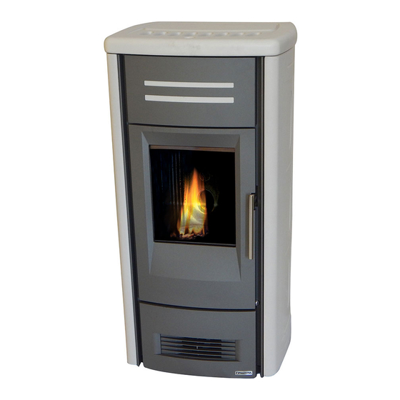
- Page 1 Pellet Stove P958 INSTRUCTIONS FOR INSTALLATION, USE AND MAINTENANCE...
-
Page 2: Important Information
In line with its policy of constant product improvement and renewal, the manufacturer may make changes without notice. This document is the property of Gruppo Piazzetta S.p.A.; no part of it may be disclosed to third parties without the written permission of Gruppo Piazzetta S.p.A. -
Page 3: Table Of Contents
1.11 Using an external flue 1.12 Prevention of domestic fires TECHNICAL CHARACTERISTICS AND SPECIFICATIONS Features Technical data Accessories and equipment Product identification data Dimensional diagram P958 Wiring diagram P958 FUEL PREPARING FOR INSTALLATION INSTALLATION Multifuoco system Electrical connections and controls... -
Page 4: General Rules
1.0 GENERAL RULES DT2010216-05 Ensure that the installation of your product conforms to all the indications given below. Fig. 1 CHIMNEY STACK SINGLE FLUEWAY OR CHIMNEY CONNECTION TO FLUE SOOT INSPECTION APERTURE FRESH AIR INTAKE END ELBOW WITH INSPECTION WINDOW MINIMUM SAFETY DISTANCES CAPACITY LOAD OF THE FLOOR DT2030321-00... -
Page 5: Single Chimney Or Flueway
Deposit of creosote If the flue pipe is an incorrect size or installed other than in compliance with the above instructions, Gruppo Piazzetta DT2030050-00 DT2030188-00 S.p.A. cannot be held liable for malfunctioning of the product, Fig. -
Page 6: Chimney Stack
DT2010025-03 1.3 ChIMNEy STACk The chimney stack is a device fitted on the top of the chimney that is designed to Fig. 7 Fig. 8 aid dispersion of the products of combustion in the atmosphere. The chimney stack must comply with the following requirements: - it must have an internal section and shape the same as the flue (A);... -
Page 7: Fresh Air Intake
DT2010539-03 1.4 FRESh AIR INTAkE To ensure trouble-free operation the stove/fireplace must have the Fig. 12 Fig. 13 necessary air available for combustion and this is provided through the fresh air intake. The fresh air intake must: - have a total free cross section at least equal to the size given in the paragraph “TECHNICAL DATA”;... -
Page 8: Capacity Load Of The Floor
Gas appliances of type B are not allowed (refer to current legislation and regulations in the place of installation). The stove or fireplace must not be used simultaneously with collective type ventilation ducts with or without extractor fan, other devices or other appliances such as: forced ventilation systems or other heating systems using ventilation to change the air. Such systems could cause a vacuum in the environment of installation even if installed in adjoining or communicating rooms. -
Page 9: Minimum Safety Distances
(wood panelling, beams or ceilings, etc) shown in figures. * = Values referred to the use of original Gruppo Piazzetta flue pipes; if other pipes are used, the safety fire regulations or fire codes of reference are applicable. - Page 10 It must also permit periodic cleaning of the flue without the need to disassemble the pipes. This type of fitting can be bought at Piazzetta retail outlets together with the pipes.
-
Page 11: Connecting To A Conventional Chimney
150 mm. It is also recommended that you insulate the chimney flue (Fig. 21-22). Pipes and bends made by Gruppo Piazzetta S.p.A. are recommended WITH DAMAGED FLUE for connection to the flueway, since they are sized to fit the flue outlet of the appliance. -
Page 12: Using An External Flue
DT2010232-02 1.11 USING AN ExTERNAL FLUE An external flue can be used provided it complies with the following Fig. 23 requirements: - use only insulated stainless steel pipes (double-lined) fixed to the outside wall of the building (Fig. 23); - there must be an inspection opening at the base of the flue to permit periodic checks and maintenance;... -
Page 13: Technical Characteristics And Specifications
(see section “MULTICOMFORT”), front hot air outlet at bottom, set-up for ducting outlet at rear (see section “MULTIFUOCO SYSTEM”) Humidifier: ......stainless steel (contains 20 cl water). DT2012006-00 2.2 TEChNICAL dATA P958 Unit (at rated power) (at minimum power) Rated / minimum thermal power 8.5 / 2.6... -
Page 14: Accessories And Equipment
DT2012008-01 2.3 ACCESSORIES ANd EqUIPMENT Description NTC 10K room sensor Provided Cable Schuco IEC L=200 Provided LCD-display remote control Provided Grate baffle plate Provided Air flap adjustment handle Provided Humidifier Provided Grey silicone paint spray Optional Pipes and elbows for connection to the flueway Optional Floor protection Optional... -
Page 15: Dimensional Diagram P958
DT2032837-00 2.5 dIMENSIONAL dIAGRAM P958 Outlet ø 8 Dimensions in cm H07026300 / DT2000786 – 00... -
Page 16: Wiring Diagram P958
DT2033413-00 2.6 wIRING dIAGRAM P958 FUN 1 SCAM. SPEED FUN 1 FUMI SCAM. COC. ACC. V2/PO AUX 2 Pos. Key to parts Pos. Key to parts N° Key to colours Emergency display Power supply with fuse (5X20 4AH250V) White Antenna... -
Page 17: Fuel
- inefficient combustion. recommend that you use high-quality pellets. Gruppo Piazzetta S.p.A has tested and programmed its stoves and Pellets should be stored in a sheltered, dry place. can ensure best performance and trouble-free operation using... -
Page 18: Installation
DT2012010-00 Pursuant to current regulations on the safety of electrical equipment, you must contact a Piazzetta After-Sales Service Centre or a qualified electrician for all and any work connected with installation, maintenance or servicing that involves access to electrical parts. - Page 19 Solution 1 - Fig. 28 - 29: Fig. 28 The stove is installed in the room which is to be heated, with the hot air directed to the front only, as when the stove arrives from the factory (Fig. 28). Alternatively the air can flow to the rear by connecting a 7.5 cm-diameter hose to the fan outlet (Fig.
- Page 20 Wall and floor ducting - Fig. 32 / 35 Fig. 32 Fig. 33 For efficient ducted heat distribution: - lag the hose with a 2 cm thick insulation (e.g. mineral fibre, ceramic fibre, rock fibre) to limit heat loss and to guarantee a sufficiently warm air temperature;...
-
Page 21: Electrical Connections And Controls
DT2011055-01 5.2 ELECTRICAL CONNECTIONS ANd CONTROLS Power cable (6) • The stove/fireplace comes with a power cable which must be Fig. 37 connected to a 230V/50Hz mains socket. Connection to the rear of the stove/fireplace is shown in fig. 39. • The power rating is indicated in the paragraph “TECHNICAL DATA”. The appliance must be connected to an efficient earthing/ grounding system. -
Page 22: Installing The Y-Element (Optional)
DT2012027-00 5.4 INSTALLING ThE y-ELEMENT (OPTIONAL) • Ducting of heat to adjoining rooms is at the user’s discretion. Fig. 43 Fig. 44 • The Y-element should be attached to the fan outlet. • Proceed as follows: - disconnect from the main power supply before opening the appliance; - remove the stove rear panel;... -
Page 23: Use
If the stove is not receiving signals from the remote try bringing the remote closer to the stove. Below are listed the various functions of the remote control’s keys. GRUPPO PIAZZETTA MENU DT2030325-00 H07026300 / DT2000786 – 00... -
Page 24: Lighting For The First Time
NUMBER KEY / DISPLAY DESCRIPTION KEY ON/OFF Allows you to start up or shut down the stove. Pressing the stand-by key and holding it down (for around 5 seconds) until KEYPAD BLOCKED appears KEY STAND-BY on the display will disable the keypad. To re-enable the keypad press the stand-by key and hold it down (for around 8 seconds) until KEYPAD UNBLOCKED appears on the display. -
Page 25: Startup And Normal Operation
DT2012018-01 6.4 STARTUP ANd NORMAL OPERATION • Before proceeding with lighting the stove: Fig. 56 ensure that the hearth door is well closed. C O N T R O L O F F • Check that the pellet hopper is full or at least contains enough pellets for the stove to run for the desired period. - Page 26 C L E A N I N G S E T T E M P S E T programmed by Gruppo Piazzetta personnel. B R A Z I E R 1 2 : 0 0 2 6 B R A Z I E R...
- Page 27 SHUTDOWN C L E A N I N G Action Description Display B R A Z I E R Hold the ON/OFF key 1 2 : 0 0 2 2 Fuel loading stops, while the cooling fan and the extractor fan continue to down for several C L E A N I N G operate until the stove has cooled.
-
Page 28: Troubleshooting
DT2012309-00 6.5 TROUbLEShOOTING A list of situations that could occur and instructions on what to do is given below. FAILED IGNITION Description Display The stove is in the startup phase, the readout “NO LIT” appears on the display and the warning buzzer sounds (if set). - Page 29 RESTARTING DURING THE SHUTDOWN PHASE Description Display SITUATION 1 The stove is in the shutdown phase and the readout CLEANING BRAZIER is on the display. W A I T The stove is restarted by the user pressing the ON/OFF key. C O O L I N G The readout “WAIT COOLING”...
-
Page 30: Control Panel
DT2010222-07 6.6 CONTROL PANEL The stove is fitted with a digital control panel to operate stove functions Fig. 57 when the LCD remote control is unavailable. The various functions of the control panel are listed below. DT2030332-00 NUMBER KEY / DISPLAY DESCRIPTION Key ON/OFF Allows you to start up or shut down the product manually. -
Page 31: Programming
DT2012020-01 6.8 PROGRAMMING The remote control can be used to select the following functions from the main MENU: • SELECT LANGUAGE LANGUAGE ITALIANO Remote control LANGUAGE PORTUGUES LANGUAGE FRANCAIS LANGUAGE ENGLISH MENU LANGUAGE ESPANOL LANGUAGE NEDERLAND LANGUAGE DEUTSCH • SET CLOCK DAY MONDAY DAY TUESDAY DAY WEDNESDAY... -
Page 32: Programming The Clock
DT2011296-00 6.9 PROGRAMMING ThE CLOCk The stove leaves the factory with the clock already set. All that needs to be done, therefore, is to check that the time is precise or if any change is needed because of summer time. Correct time setting is necessary to be able to use all the functions where time is involved. -
Page 33: Timer
DT2010242-05 6.10 TIMER The timer allows the user to programme the stove to start up and shut down automatically without any manual intervention. Daily, weekly and weekend programmes can be selected with a maximum of two operating cycles in two separate timetable bands. For example: Cycle 1: from 6am until 9am. - Page 34 C H R O N O C H R O N O C H R O N O C H R O N O P R O G R A M P R O G R A M P R O G R A M C H R O N O C H R O N O P R O G R A M...
- Page 35 WEEK PROGRAMME Function Action Display S E T S E T S E T S E T Select set chrono Press the MENU key. Using the SELECT MENU key select the SET CHRONO S E T S E T C H R O N O S E T C H R O N O menu...
- Page 36 Function Action Display S E T S E T S E T S E T S E T S E T S E T S E T Set desired power for Press SELECT MENU to set the desired power (for example you want C H R O N O C H R O N O P O W E R...
- Page 37 WEEKEND PROGRAMME Function Action Display S E T S E T Select set chrono Press the MENU key. Using the SELECT MENU key select the SET CHRONO C H R O N O C H R O N O menu menu and confirm by pressing the SET key.
- Page 38 L I T Function Action Display S E T S E T Set desired power for Press SELECT MENU to set the desired power (for example you want P O W E R first operating cycle P O W E R power setting 1).
-
Page 39: Multicomfort
DT2010251-03 6.11 MULTICOMFORT The pellet stove is fitted with the Multicomfort function. This works in conjunction with the Multifuoco ventilation system to improve heat distribution. It allows the room temperature to be read from the stove or from the remote control, so that the Multifuoco settings can be varied according to the requirements of the rooms to be heated. - Page 40 by the user, the stove automatically goes to power level 1 (readout “OK” on the display). If the room temperature continues to rise with operation at power level 1 up to the value set on the STOP function (e.g. + 2°C compared to the programmed temperature), the stove shuts down and goes into the stand-by mode.
-
Page 41: Parameter Menu
DT2011866-00 6.13 PARAMETER MENU The User can only interact with the LOADING AUGER and MEMORY COUNTERS in the parameter menu, as described in the table below: the other parameters can only be used by an authorised service centre. LOADING AUGER When the stove is new or the pellets have been completely used up, prior to startup and ignition, carry out the LOADING AUGER function. - Page 42 HOUR COUNTER MEMORY Function Action M E N U Display M E N U M E N U P A R A M E T E R M E N U P A R A M E T E R M E N U P A R A M E T E R M E N U...
-
Page 43: Enable Beep (Audio Signal)
DT2040065-03 6.14 ENAbLE bEEP (AUdIO SIGNAL) This function allows you to engage or disengage the alarm signal emitted by the stove to indicate that it has received the remote control’s commands. ENABLE BEEP (audio signal) Function Action Display E N A B L E E N A B L E Select enable beep Press the MENU key. -
Page 44: Modifying The Transmission Unit
DT2010248-04 6.16 MOdIFyING ThE TRANSMISSION UNIT Should two pellet stoves of the same model be installed close to each other and the remote control beam activates both simultaneously, it is possible to modify the transmission unit when the stove has been shut down by taking the following steps: SELECT UNIT Function Action... -
Page 45: Safety Devices
DT2012313-00 6.18 SAFETy dEvICES During operation some parts of the stove (door, handle, ceramic parts) can reach high temperatures. Remember to maintain the safety distances indicated previously. Be careful, take all due precautions and always comply with the instructions. If during operation smoke leaks from any part of the stove or the flue, shut the stove down immediately and ventilate the room. When the stove has cooled, check for the cause of the leak and if necessary call in specialist personnel. - Page 46 FLUE GAS TEMPERATURE SENSOR Description Display A sensor positioned at the flue gas outlet and connected to the PCB constantly monitors the working temperature allowing the stove to be used in all safety. S A F E T Y The readout “SAFETY STOVE” appears on the display. If the flue gas temperature exceeds the fixed safety limit, the power supply to the fuel-loading auger S T O V E is cut off thus depriving the grate of pellets and starting the stove shutdown process.
-
Page 47: Opening The Door
STOVE ROOM TEMPERATURE SENSOR Description Display A sensor is connected to the rear of the stove; it constantly monitors the temperature in the immediate vicinity of the stove to ensure that it can be operated in all safety. The symbol “00” appears on the display in place of the room temperature. L E V E L It means that the sensor has been momentarily disconnected or accidentally dislodged. -
Page 48: Maintenance
DT2010249-01 Pursuant to current regulations on the safety of electrical equipment, you must contact a Piazzetta Group After-Sales Service Centre or a qualified electrician for all and any work connected with installation, maintenance or servicing that involves access to electrical parts. -
Page 49: Cleaning The Smoke Chamber
DT2010127-03 7.4 CLEANING ThE SMOkE ChAMbER Once a year clean the smoke chamber as follows: Fig. 62 - remove the screws which secure the smoke chamber cover, then lift it slightly and take it out by pulling it towards you (Fig. 62 - 63); DT2032880-00 Fig. -
Page 50: Cleaning The Ceramic Cladding
The stove is fitted with a 4 mm thick glass panel, resistant to thermal shock up to 750°C; the glass can only be broken by heavy impact or misuse. Do not slam the door or hit the window. In case of breakage replace only with a Gruppo Piazzetta spare part. To replace, proceed as follows: - wear protective gloves;... -
Page 51: Replacing The Remote Control Batteries
It is necessary to have the fans cleaned at least once a year. Since such a procedure involves dismantling certain parts of the stove, have the cleaning carried out only by a Piazzetta DT2033447-00 Service Centre or other qualified persons. -
Page 52: When Not In Use
DT2011801-00 7.12 whEN NOT IN USE When shutting the stove down for the summer, proceed as follows: - remove all pellets from the hopper and feeding auger; - carefully clean the grate, the grate support and the ash drawer; - using a steel brush, clean the baffle plate or internal baffle plates of the firebox and coat them using the spray paint, supplied on request, to prevent them from oxidising and consequently forming rust. -
Page 53: Troubleshooting
It is therefore recommended that only “Gruppo Piazzetta S.p.A.” authorised Service Centres be contacted. Whenever authorised Service Centre personnel carry out work, they must show an identity card issued by Gruppo Piazzetta S.p.A. on which the following are printed: name of the Service Centre, stamp and signature of the company and the period of validity of the actual document. - Page 54 Replace the pressure switch (use only Faulty pressure switch “ALF 2” stove status original spares) Check the electrical connections (contact a Piazzetta After-Sales No power supply to the auger Service Centre or an authorised person) Thermal cutout “ALC” stove status...
- Page 55 Pellet-charging system blocked clean the auger and chute This instruction booklet contains all the necessary information for installation, operation and maintenance. Only call the Gruppo Piazzetta S.p.A. service centre after having scrupulously followed all the instructions. H07026300 / DT2000786 – 00...
-
Page 56: Replacing The Fuses
DT2010557-03 8.1 REPLACING ThE FUSES Electronic board fuse. Fig. 69 Unscrew the cartridge fuse or safety plug from the electronic board and replace with a similar one. Motherboard fuse type: F4AL250V. Cartridge fuse/safety plug DT2032940-00 Fuse on the IEC power socket. Fig. -
Page 57: Declaration Of Conformity
DICHIARAZIONE DI CONFORMITA’ DECLARATION OF CONFORMITY Il sottoscritto, rappresentante il seguente costruttore The undersigned, representative of the following manufacturer Gruppo Piazzetta S.p.A. Via Montello, 22 31010 Casella D’Asolo (TV) – ITALY DICHIARA che l’apparecchiatura descritta in appresso: DECLARES that the product:... -
Page 58: Declaration Of Conformity Transceiver Unit Multicomfort
DICHIARAZIONE DI CONFORMITA’ DECLARATION OF CONFORMITY Il sottoscritto, rappresentante il seguente costruttore The undersigned, representative of the following manufacturer Gruppo Piazzetta S.p.A. Via Montello, 22 31010 Casella D’Asolo (TV) – ITALY DICHIARA che l’apparecchiatura descritta in appresso: DECLARES that the product:... -
Page 59: European Regulations
EUROPEAN REGULATIONS DT2010382-05 This product “Pellet Stove P958” with Multicomfort has been designed, tested and manufactured according to the European R&TTE Directives 1999/5/EC. Following these Directives, this product can be installed in the following countries: (BE) (IRE) (PT) (DE) Belgium... - Page 60 Product serial number, to be quoted when requesting service from the Gruppo Piazzetta After-Sales Service Centre. Via Montello, 22 31011 Casella d’Asolo (TV) - ITALY Tel. +39.04235271 - Fax +39.042355178 www.piazzetta.it e-mail:infopiazzetta@piazzetta.it...
Need help?
Do you have a question about the P958 and is the answer not in the manual?
Questions and answers
What mean search field