Table of Contents
Advertisement
Quick Links
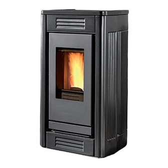
Pellet Stove
P957
INSTRUCTIONS FOR INSTALLATION,
USE AND MAINTENANCE
Please read this entire manual before installation and use of this
pellet fuel-burning room heater. Failure to follow these instructions
could result in property damage, bodily injiury or even death.
Contact local building or fire officials about restrictions and
installation inspection requirements in your area.
Save these Instructions.
Advertisement
Table of Contents
Troubleshooting

Subscribe to Our Youtube Channel
Related Manuals for Piazzetta P957


Summary of Contents for Piazzetta P957
- Page 1 Pellet Stove P957 INSTRUCTIONS FOR INSTALLATION, USE AND MAINTENANCE Please read this entire manual before installation and use of this pellet fuel-burning room heater. Failure to follow these instructions could result in property damage, bodily injiury or even death. Contact local building or fire officials about restrictions and installation inspection requirements in your area.
-
Page 2: Important Information
In line with its policy of constant product improvement and renewal, the manufacturer may make changes without notice. This document is the property of Gruppo Piazzetta S.p.A.; no part of it may be disclosed to third parties without the written permission of Gruppo Piazzetta S.p.A. -
Page 3: Table Of Contents
1.13 Prevention of domestic fires 1.14 Mobile home installation TECHNICAL CHARACTERISTICS AND SPECIFICATIONS Features Technical data Accessories and equipment Product identification data Dimensional diagram P957 Wiring diagram P957 FUEL PREPARING FOR INSTALLATION INSTALLATION Multifuoco System Electrical connections and controls Installing the external thermostat... -
Page 4: General Rules
1.0 GENERAL RULES DT2010216-05 Ensure that the installation of your product conforms to all the indications given below. Fig. 1 CHIMNEY STACK SINGLE FLUEWAY OR CHIMNEY CONNECTION TO FLUE SOOT INSPECTION APERTURE FRESH AIR INTAKE END ELBOW WITH INSPECTION WINDOW MINIMUM SAFETY DISTANCES CAPACITY LOAD OF THE FLOOR DT2030321-00... -
Page 5: Fresh Air Intake
DT2010539-03 1.2 FRESh AIR INTAkE To ensure trouble-free operation the stove must have the necessary Fig. 2 air available for combustion and this is provided through the fresh air intake. The fresh air intake must: - have a total free cross section at least equal to the size given in the paragraph “TECHNICAL DATA”;... -
Page 6: Capacity Load Of The Floor
DT2010032-00 1.5 CAPACITy LOAd OF ThE FLOOR Check the load-bearing capacity of the floor, referring to the weight of the product given in the paragraph “TECHNICAL DATA”. If the floor does not have a suitable load-bearing capacity, adequate countermeasures must be taken. DT2011553-02 1.6 MINIMUM SAFETy dISTANCES Install the product in compliance with the recommended safety distances... -
Page 7: Flueway
DT2010229-05 1.7 FLUEwAy The stove requires a UL listed pellet vent. So the venting system shall be approved for pellet stoves by a certified testing Laboratory. PL Vent must be used for venting all Freestanding stoves. Do not use to vent pellet appliance these venting materials and products: - Dryer vent - Gas appliance (Type B) vent - PVC (plastic) pipe... - Page 8 Where 4” diameter pipe must be used, connect it to the stove flue outlet Fig. 8 with a 3” union-tee then use a 3” – 4” adaptor (Fig. 8). Ø 4" Ø 3" PELLET STOVE TEE W/TEE CAP DT2033009-00 Union-tee The use of this type of fitting must allow for the collection of condensate Fig.
-
Page 9: Interior Vent Installation
DT2010230-03 1.8 INTERIOR vENT INSTALLATION This kind of installation provides the natural draft that results from Fig. 10 a vertical rise avoiding smoke being released into the house when RAIN CAP electricity to the unit is interrupted while burning or smoldering pellets remains in the burn grate. -
Page 10: Connecting To A Conventional Chimney
DT2010232-02 1.9 CONNECTING TO A CONvENTIONAL ChIMNEy The stove may be connected to an existing Class A chimney or a masonry Fig. 12 chimney which meets the minimum requirements of NFPA 211. Using this kind of installation the pellet stove is able to draft naturally without exhaust blower operation (failure), reducing the probability of burn-back and back-drafting. -
Page 11: Installing Into An Existing Fireplace Chimney
DT2010232-02 1.10 INSTALLING INTO AN ExISTING FIREPLACE ChIMNEy This kind of installation also provides natural draft in the event of a Fig. 15 power failure. When installing as a hearth mount stove into a fireplace the unit must either be relined, terminating above the chimney chase top, or positively connected to the existing chimney system using a block off plate (Fig. -
Page 12: Venting: Termination Requirements
This configuration will help prevent blockage of vent by snow drifts. Also the minimum vertical run of 5 feet (1,5 m) ensures the ventilation of the exhaust in the event of a power failure, and allow for easier cleaning through cleanout on tee. Certain local code restrictions may apply. -
Page 13: Prevention Of Domestic Fires
The clearance to a door, window or cavity must be at least: - 1.5’ (458 mm) below; - 1.5’ (458 mm) horizontally; - 9’’ (230 mm) above. The clearance to fresh air intake for combustion of the pellet stove or any other appliance, or the non-mechanical air supply inlet to the building must be at least 4’... -
Page 14: Mobile Home Installation
DT2010027-02 1.14 MObILE hOME INSTALLATION The stove has been tested and listed for mobile home installations. Unit must be installed in accordance with the: Manufactured Home and Safety Standard (HUD), CFR 3280, Part 24. In addition to all previously detailed requirements, mobile home installations must observe the following: - Permanently bolt the stove to the floor. -
Page 15: Technical Characteristics And Specifications
(see section “MULTICOMFORT”), front hot air outlet at bottom, set-up for ducting outlet at rear (see section “MULTIFUOCO SYSTEM”) Humidifier: ......stainless steel contains 17 oz (50 cl) water DT2012363-00 2.2 TEChNICAL dATA P957 Unit (at rated power) (at minimum power) Heat input BTU/H / (kW) 37523 / (11.0) -
Page 16: Accessories And Equipment
DT2011789-00 2.3 ACCESSORIES ANd EqUIPMENT Description NTC 10K room sensor In kit Flexible cable L = 5.9’ / (180 cm) In kit LCD remote control In kit Door handle tool In kit Grate baffle plate In kit Silicone paint spray can In kit Humidifier In kit... -
Page 17: Dimensional Diagram P957
DT2033373-00 2.5 dIMENSIONAL dIAGRAM P957 42,6" Ø 1,97" (1082 mm) (50 mm) Ø 2,95" (75 mm) 16,3" (414 mm) 9,41" (239 mm) 5,39" (137 mm) 0,99" (25 mm) 4,34" (110 mm) 6,89" 5,98" (175 mm) (152 mm) 20,48" (520 mm) 23,01"... -
Page 18: Wiring Diagram P957
DT2033257-00 2.6 wIRING dIAGRAM P957 Capacitor BLACK Receiver unit YELLOW GREEN Room fan WHITE (blower) WHITE BLUE BROWN FUN1 SCAMB SPEED FUN1 SPEED Ventilation FUN2 electronic board Fuel feed Flue gas fan auger motor FUN2 BLUE YELLOW GREEN N.O. Fire door... -
Page 19: Fuel
- inefficient combustion. recommend that you use high-quality pellets. Gruppo Piazzetta S.p.A has tested and programmed its stoves and Pellets should be stored in a sheltered, dry place. can ensure best performance and trouble-free operation using... -
Page 20: Installation
DT2010116-02 Pursuant to current regulations on the safety of electrical equipment, you must contact a Piazzetta After-Sales Service Centre or a qualified electrician for all and any work connected with installation, maintenance or servicing that involves access to electrical parts. - Page 21 Solution 1 - Fig. 28 - 29: Fig. 28 The stove is installed in the room which is to be heated, with the hot air directed to the front only, as when the stove arrives from the factory (Fig. 28). Alternatively the air can flow to the rear by connecting a 3” / 75 mm-diameter flexible pipe to the fan outlet (Fig.
- Page 22 Wall and floor ducting - Fig. 32 / 35 Fig. 32 Fig. 33 For efficient ducted heat distribution: - lag the flexible pipe with a 0.79” / (2 cm) thick insulation (e.g. mineral fibre, ceramic fibre, rock fibre) to limit heat loss and to guarantee a sufficiently warm air temperature;...
-
Page 23: Electrical Connections And Controls
DT2011055-01 5.2 ELECTRICAL CONNECTIONS ANd CONTROLS Power cable (6) Fig. 38 • The stove/fireplace comes with a power cable which must be connected to a 230V/50Hz mains socket. Connection to the rear of the stove/fireplace is shown in fig. 40. • The power rating is indicated in the paragraph “TECHNICAL DATA”. The appliance must be connected to an efficient earthing/ grounding system. -
Page 24: Installing The Y-Element (Optional)
DT2010123-02 5.4 INSTALLING ThE y-ELEMENT (OPTIONAL) • Ducting of heat to adjoining rooms is at the user’s discretion. Cutting the Fig. 44 Fig. 45 Loosen the hose hose clip • The Y-element should be attached to the fan outlet. • Proceed as follows: - disconnect from the main power supply before opening the appliance. -
Page 25: Use
A high torque motor that is capable of doing serious harm to fingers drives the auger and for this reason in Piazzetta pellet stoves a protective grille inside the hopper is placed. -
Page 26: Remote Control
If the stove is not receiving signals from the remote try bringing the remote closer to the stove. Below are listed the various functions of the remote control’s keys. GRUPPO PIAZZETTA MENU DT2030325-00 NUMBER... -
Page 27: Lighting For The First Time
DT2010082-05 6.3 LIGhTING FOR ThE FIRST TIME • Carefully read this “Instructions for Installation, Use and Maintenance“ in its entirety before lighting your stove for the first time. • Before lighting the stove for the first time, check that the grate is properly placed and pushed back towards the baffle plate. • There will be odours when lighting the first few times due to the evaporation of paints and oils used during the manufacturing process. - Page 28 S T A R T STARTUP P H A S E Action Description Display 1 2 : 0 0 7 3 F A cycle starts with three phases which take the stove into the normal operating mode: C O N T R O L C O N T R O L C O N T R O L 1 2 : 0 0 7 3 F...
- Page 29 V E N T - 1 C L E A N I N G C L E A N I N G programmed by Gruppo Piazzetta personnel. G R A T E G R A T E This operation removes ash deposits and other buildups, which would...
-
Page 30: Troubleshooting
EXTERNAL THERMOSTAT Action Description Display Stove operation can be regulated by any kind of external room thermostat connected to the electronic board. To connect the thermostat, see paragraph “INSTALLING THE EXTERNAL ROOM THERMOSTAT”. Operation of the external thermostat depends on the stove temperature setting. - Page 31 FAILED IGNITION: WHAT TO DO C L E A N I N G Action Description Display B R A Z I E R Shut the stove down 1 2 : 0 0 2 2 by pressing the • The warning buzzer stops. C L E A N I N G ON/OFF key down for • The readout CLEANING GRATE appears on the display and when the...
- Page 32 INTERRUPTION OF POWER SUPPLY Action Description Display If there is a blackout while the stove is in operation, there are two possibilities of procedure according to stove set-up: - blackout without timer thermostat settings. - blackout with timer thermostat settings. Blackout without timer thermostat settings.
-
Page 33: Control Panel
DT2010222-07 6.6 CONTROL PANEL The stove is fitted with a digital control panel to operate stove functions Fig. 56 when the LCD remote control is unavailable. The various functions of the control panel are listed below. DT2030332-00 NUMBER KEY / DISPLAY DESCRIPTION Key ON/OFF Allows you to start up or shut down the product manually. -
Page 34: Programming
DT2011867-01 6.8 PROGRAMMING The remote control can be used to select the following functions from the main MENU: • SELECT LANGUAGE LANGUAGE ENGLISH Remote control LANGUAGE ITALIANO LANGUAGE DEUTSCH LANGUAGE FRANCAIS MENU • UNIT OF MEASUREM • SET CLOCK DAY MONDAY DAY TUESDAY DAY WEDNESDAY DAY THURSDAY... -
Page 35: Setting Unit Of Temperature Measurement
DT2011296-00 6.9 SETTING UNIT OF TEMPERATURE MEASUREMENT This function allows the unit of temperature measurement in CELSIUS or in FAHRENHEIT to be set on the display. UNIT OF MEASUREMENT U N I T O F Function Action Display M E A S U R E M U N I T O F M E A S U R E M U N I T O F... -
Page 36: Programming The Clock
DT2011296-00 6.10 PROGRAMMING ThE CLOCk The stove leaves the factory with the clock already set. All that needs to be done, therefore, is to check that the time is precise or if any change is needed because of summer time. Correct time setting is necessary to be able to use all the functions where time is involved. -
Page 37: Timer
DT2010242-05 6.11 TIMER The timer allows the user to programme the stove to start up and shut down automatically without any manual intervention. Daily, weekly and weekend programmes can be selected with a maximum of two operating cycles in two separate timetable bands. For example: Cycle 1: from 6am until 9am. - Page 38 C H R O N O C H R O N O C H R O N O C H R O N O P R O G R A M P R O G R A M P R O G R A M C H R O N O C H R O N O P R O G R A M...
- Page 39 WEEK PROGRAMME Function Action Display S E T S E T S E T S E T Select set chrono Press the MENU key. Using the SELECT MENU key select the SET CHRONO S E T S E T C H R O N O S E T C H R O N O menu...
- Page 40 Function Action Display S E T S E T S E T S E T S E T S E T S E T S E T Set desired power for Press SELECT MENU to set the desired power (for example you want C H R O N O C H R O N O P O W E R...
- Page 41 WEEKEND PROGRAMME Function Action Display S E T S E T Select set chrono Press the MENU key. Using the SELECT MENU key select the SET CHRONO C H R O N O C H R O N O menu menu and confirm by pressing the SET key.
- Page 42 L I T Function Action Display S E T S E T Set desired power for Press SELECT MENU to set the desired power (for example you want P O W E R first operating cycle P O W E R power setting 1).
-
Page 43: Multicomfort
DT2010251-03 6.12 MULTICOMFORT The pellet stove is fitted with the Multicomfort function. This works in conjunction with the Multifuoco ventilation system to improve heat distribution. It allows the room temperature to be read from the stove or from the remote control, so that the Multifuoco settings can be varied according to the requirements of the rooms to be heated. - Page 44 the power level previously set by the user. The stove only restarts when the temperatures measured on the actual stove allow its use in all safety. If the STOP and OFF functions are enabled, upon reaching the programmed room temperature, the stove will operate in the conventional way by going to power level 1 without shutting down.
-
Page 45: Parameter Menu
DT2011866-00 6.14 PARAMETER MENU The User can only interact with the TIME METER STORAGE in the parameter menu, as described in the table below: the other parameters can only be used by an authorised service centre. HOUR COUNTER MEMORY Function Action M E N U Display... -
Page 46: Enable Beep (Audio Signal)
DT2010248-04 6.15 ENAbLE bEEP (AUdIO SIGNAL) This function allows you to engage or disengage the alarm signal emitted by the stove to indicate that it has received the remote control’s commands. ENABLE BEEP (audio signal) Function Action Display E N A B L E E N A B L E Select enable beep Press the MENU key. -
Page 47: Modifying The Transmission Unit
DT2010248-04 6.17 MOdIFyING ThE TRANSMISSION UNIT Should two pellet stoves of the same model be installed close to each other and the remote control beam activates both simultaneously, it is possible to modify the transmission unit when the stove has been shut down by taking the following steps: SELECT UNIT Function Action... -
Page 48: Safety Devices
DT2010994-00 6.19 SAFETy dEvICES During operation some parts of the stove (door, handle, ceramic parts) can reach high temperatures. Remember to maintain the safety distances indicated previously. Be careful, take all due precautions and always comply with the instructions. If during operation smoke leaks from any part of the stove or the flue, shut the stove down immediately and ventilate the room. When the stove has cooled, check for the cause of the leak and if necessary call in specialist personnel. - Page 49 PELLET HOPPER HOUSING TEMPERATURE Sensor Description Display Located on the pellet hopper, its function is to prevent excessive temperature ranges. WHEN ACTIVATED T A N K T E M P If the pellet hopper temperature reaches critical levels, the thermostat cuts off the power supply to the fuel-loading auger, thereby stopping the S A F E T Y supply of pellets to the grate and starting the stove shutdown process.
-
Page 50: Opening The Door
STOVE ROOM TEMPERATURE SENSOR Sensor Description Display Connected to the rear of the stove, it constantly monitors the temperature in the immediate vicinity of the stove to ensure that it can be operated in all safety. WHEN ACTIVATED L E V E L If the sensor is momentarily or accidentally removed from its normal position, the problem does not require the immediate shutdown of the Room sensor... -
Page 51: Humidifier For Stove
DT2010993-00 6.21 hUMIdIFIER FOR STOvE A humidifier tank is a standard part of the stove and is fitted inside the Fig. 59 stove at the top under the grille in front of the pellet hopper. Use the spray bottle provided in the kit to fill the tank with water, inserting the nozzle into the relative hole made in the grille. -
Page 52: Maintenance
DT2010249-01 Pursuant to current regulations on the safety of electrical equipment, you must contact a Piazzetta Group After-Sales Service Centre or a qualified electrician for all and any work connected with installation, maintenance or servicing that involves access to electrical parts. -
Page 53: Cleaning The Smoke Chamber
DT2010127-03 7.4 CLEANING ThE SMOkE ChAMbER Once a year clean the smoke chamber as follows: Fig. 63 - remove the screws which secure the smoke chamber cover, then lift it slightly and take it out by pulling it towards you (Fig. 63 - 64); DT2030185-01 Fig. -
Page 54: Cleaning The Ceramic Cladding
The stove is fitted with a 0.197” / (5 mm) thick glass panel, resistant to thermal shock up to 1382°F / (750°C); the glass can only be broken by heavy impact or misuse. Do not slam the door or hit the window. In case of breakage replace only with a Gruppo Piazzetta spare part. To replace, proceed as follows: - wear protective gloves;... -
Page 55: Replacing The Remote Control Batteries
Any build-up of dust or ash on the blades can unbalance them resulting in noise during operation. It is necessary to have the fans cleaned annually. Since such an operation involves dismantling certain parts of the stove, have the cleaning carried out only by a Piazzetta Service Centre or other qualified persons. DT2010096-05 7.12 whEN NOT IN USE... -
Page 56: Troubleshooting
It is therefore recommended that only “Gruppo Piazzetta S.p.A.” authorised Service Centres be contacted. Whenever authorised Service Centre personnel carry out work, they must show an identity card issued by Gruppo Piazzetta S.p.A. on which the following are printed: name of the Service Centre, stamp and signature of the company and the period of validity of the actual document. - Page 57 Replace the pressure switch (use only Faulty pressure switch “ALF 2” stove status original spares) Check the electrical connections (contact a Piazzetta After-Sales No power supply to the auger Service Centre or an authorised person) Thermal cutout “ALC” stove status...
- Page 58 Empty the pellet hopper; check and Pellet-charging system blocked clean the auger and chute This instruction booklet contains all the necessary information for installation, operation and maintenance. Only call the Gruppo Piazzetta S.p.A. service centre after having scrupulously followed all the instructions. H07025700/DT2000725 – 01...
-
Page 59: Replacing The Fuses
DT2010557-02 8.1 REPLACING ThE FUSES Electronic board fuse. Fig. 68 Unscrew the cartridge fuse or safety plug from the electronic board and replace with a similar one. Motherboard fuse type: F6.3AL250V. Bouchon porte-fusible DT2032940-00 Fuse on the IEC power socket. Fig. - Page 60 Product serial number, to be quoted when requesting service from the Gruppo Piazzetta After-Sales Service Centre. Via Montello, 22 31011 Casella d’Asolo (TV) - ITALY Tel. +39.04235271 - Fax +39.042355178 www.piazzetta.it e-mail:infopiazzetta@piazzetta.it...
Need help?
Do you have a question about the P957 and is the answer not in the manual?
Questions and answers