Piazzetta P963 THERMO Instructions For Installation, Use And Maintenance Manual
Hide thumbs
Also See for P963 THERMO:
Table of Contents
Advertisement
Quick Links
Advertisement
Table of Contents
Troubleshooting

Subscribe to Our Youtube Channel
Related Manuals for Piazzetta P963 THERMO


Summary of Contents for Piazzetta P963 THERMO
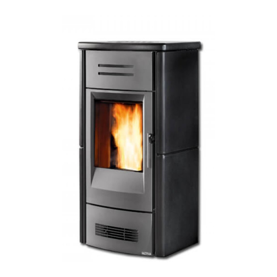
- Page 1 Pellet Stove P963 THERMO INSTRUCTIONS FOR INSTALLATION, USE AND MAINTENANCE...
- Page 2 In line with its policy of constant product improvement and renewal, the manufacturer may make changes without notice. This document is the property of Gruppo Piazzetta S.p.A.; no part of it may be disclosed to third parties without the written permission of Gruppo Piazzetta S.p.A.
-
Page 3: Table Of Contents
1.12 Prevention of domestic fires TECHNICAL CHARACTERISTICS AND SPECIFICATIONS Description of the applicance Technical data Features Accessories and equipment Product identification data Dimensional diagram P963 THERMO Wiring diagram P963 THERMO FUEL PREPARING FOR INSTALLATION INSTALLATION Water connections Water pipe connections... -
Page 4: General Rules
1.0 GENERAL RULES DT2010216-05 Ensure that the installation of your product conforms to all the indications given below. Fig. 1 CHIMNEY STACK SINGLE FLUEWAY OR CHIMNEY CONNECTION TO FLUE SOOT INSPECTION APERTURE FRESH AIR INTAKE END ELBOW WITH INSPECTION WINDOW MINIMUM SAFETY DISTANCES CAPACITY LOAD OF THE FLOOR DT2030321-00... -
Page 5: Single Chimney Or Flueway
Ø If the flue pipe is an incorrect size or installed other than in Deposit of creosote compliance with the above instructions, Gruppo Piazzetta S.p.A. cannot be held liable for malfunctioning of the product, DT2030050-00 DT2030188-00 damage to property or injury to persons or animals. -
Page 6: Chimney Stack
DT2010025-03 1.3 ChIMNEy STACk The chimney stack is a device fitted on the top of the chimney that is designed to Fig. 7 Fig. 8 aid dispersion of the products of combustion in the atmosphere. The chimney stack must comply with the following requirements: - it must have an internal section and shape the same as the flue (A);... -
Page 7: Fresh Air Intake
DT2010539-03 1.4 FRESh AIR INTAkE To ensure trouble-free operation the stove/fireplace must have the Fig. 12 Fig. 13 necessary air available for combustion and this is provided through the fresh air intake. The fresh air intake must: - have a total free cross section at least equal to the size given in the paragraph “TECHNICAL DATA”;... -
Page 8: Capacity Load Of The Floor
Gas appliances of type B are not allowed (refer to current legislation and regulations in the place of installation). The stove or fireplace must not be used simultaneously with collective type ventilation ducts with or without extractor fan, other devices or other appliances such as: forced ventilation systems or other heating systems using ventilation to change the air. Such systems could cause a vacuum in the environment of installation even if installed in adjoining or communicating rooms. -
Page 9: Minimum Safety Distances
(wood panelling, beams or ceilings, etc) shown in figures. * = Values referred to the use of original Gruppo Piazzetta flue pipes; if other pipes are used, the safety fire regulations or fire codes of reference are applicable. - Page 10 It must also permit periodic cleaning of the flue without the need to disassemble the pipes. This type of fitting can be bought at Piazzetta retail outlets together with the pipes.
-
Page 11: Connecting To A Conventional Chimney
150mm. It is also recommended that you insulate the chimney flue (Fig. 21-22). Pipes and bends made by Gruppo Piazzetta S.p.A. are recommended WITH DAMAGED FLUE for connection to the flueway, since they are sized to fit the flue outlet of the appliance. -
Page 12: Using An External Flue
DT2010232-02 1.11 USING AN ExTERNAL FLUE An external flue can be used provided it complies with the following Fig. 23 requirements: - use only insulated stainless steel pipes (double-lined) fixed to the outside wall of the building (Fig. 23); - there must be an inspection opening at the base of the flue to permit periodic checks and maintenance;... -
Page 13: Technical Characteristics And Specifications
2.0 TEChNICAL ChARACTERISTICS ANd SPECIFICATIONS DT2012289-00 DT2012290-00 2.1 dESCRIPTION OF ThE APPLICANCE Fig. 24 Fig. 26 DT2033288-00 DT2033289-00 Fig. 25 Fig. 27 DT2033290-00 DT2033291-00 N° Description N° Description Smoke chamber bottom plate 13 Top surround Ash guard 14 Expansion tank Tube-cleaning tool 15 Relief valve Allen wrench... -
Page 14: Technical Data
DT2012291-01 2.2 TEChNICAL dATA P963 THERMO Unit (at rated power) (at minimum power) Thermal power 15.5 Thermal power of fluid (water) 12.5 Hourly fuel consumption kg/h Efficiency 90.5 92.0 CO content (with 13% O 0.020 0.030 Maximum power rating Power rating at work... -
Page 15: Features
DT2012292-01 2.3 FEATURES Cladding: ......in hand-made majolica Interior: ........ in steel Baffle plate and hearth: ..in cast iron Grate: ........in cast iron Door: ........in cast iron with ceramic glass heat resistant up to 750°C Handle: ........ in steel with nickel-plated finish Control panel: ...... -
Page 16: Dimensional Diagram P963 Thermo
DT2033292-00 2.6 dIMENSIONAL dIAGRAM P963 ThERMO Key: S = temperature/pressure relief valve F 1/2" R = system return M 3/4" M = system delivery M 3/4" Dimensions in cm H07027850 / DT2000931 – 01... -
Page 17: Wiring Diagram P963 Thermo
DT2032961-01 2.7 wIRING dIAGRAM P963 ThERMO Pos. Key to parts Pos. Key to parts N° Key to colours Emergency display Smoke sensor White Antenna Yellow-green N.O. External thermostat (normaly open) Black Coclea Serial port DB9 Brown Flue gas fan Motherboard... -
Page 18: Fuel
- inefficient combustion. recommend that you use high-quality pellets. Gruppo Piazzetta S.p.A has tested and programmed its stoves and Pellets should be stored in a sheltered, dry place. can ensure best performance and trouble-free operation using... -
Page 19: Preparing For Installation
4.0 PREPARING FOR INSTALLATION DT2012244-06 To prevent accidents or damage to the product we recommend the following: - unpacking and installation must be carried out by at least two people; - every operation involving movement of the product must be carried out with the proper tools in full compliance with current safety regulations;... -
Page 20: Installation
DT2012100-00 Pursuant to current regulations on the safety of electrical equipment, you must contact a Piazzetta After-Sales Service Centre or a qualified electrician for all and any work connected with installation, maintenance or servicing that involves access to electrical parts. -
Page 21: Water Pipe Connections
Use sections of hose to connect the appliance so that it can be The expansion tank installed inside the appliance, with moved slightly (check that any kinks in the hose do not allow capacity and pre-filling pressure indicated on the rating plate, air pockets to form). -
Page 22: Electrical Connections And Controls
DT2012104-00 5.3 ELECTRICAL CONNECTIONS ANd CONTROLS Power cable (6) Connection to the DB9 serial socket (7) • The stove/fireplace comes with a power cable which must be • The appliance has a DB9 serial socket, which is used to check connected to a 230V/50Hz mains socket. Connection to the rear of appliance operation. -
Page 23: Installing The Aux Thermostat
DT2012106-01 5.5 INSTALLING ThE AUx ThERMOSTAT The AUX thermostat activates an output from the electronic control board at 230 V when a certain settable SET temperature is reached (see ”USE”). If the temperature of the water in the boiler read by the electronic sensor is higher than the AUX THERMOSTAT SET point temperature, the ends of the cable connected to the Y terminal will be powered at 230 V. -
Page 24: Use
If the stove is not receiving signals from the remote try bringing the remote closer to the stove. Below are listed the various functions of the remote control’s keys. GRUPPO PIAZZETTA MENU DT2030325-00 H07027850 / DT2000931 – 01... -
Page 25: Lighting For The First Time
NUMBER KEY / DISPLAY DESCRIPTION Key ON/OFF Allows you to start up or shut down the stove. Pressing the stand-by key and holding it down (for around 5 seconds) until KEYPAD BLOCKED Key STAND-BY appears on the display will disable the keypad. To re-enable the keypad press the stand-by key and hold it down (for around 8 seconds) until KEYPAD UNBLOCKED appears on the display. -
Page 26: Startup And Normal Operation
DT2012018-01 6.4 STARTUP ANd NORMAL OPERATION • Before proceeding with lighting the stove: Fig. 45 Ensure that the hearth door is well closed. O F F • Check that the pellet tank is full or at least contains enough pellets for the stove to run for the desired period. • When the stove is connected to the power supply but is not yet lit, the display will show the readout OFF and in the lower half the current 0 9 : 5 3... - Page 27 C L E A N I N G periodically, the frequency varying according to the settings pre- C L E A N I N G programmed by Gruppo Piazzetta personnel. B R A Z I E R B R A Z I E R...
- Page 28 USER MODE: AUTO MODE U S E R Action Description Display U S E R M O D E It is possible to set a mode of operation that is simpler to manage, in which M O D E U S E R just the water temperature needs to be set and the electronics do all the M O D E rest.
- Page 29 EXTERNAL THERMOSTAT Action Description Display Operation of the external thermostat depends on the function that the user selects through the programming menu under the item EXTERNAL THERMOSTAT (see “PROGRAMMING”). If MODULATION has been selected, when the thermostat activates the appliance promptly goes to minimum power, whereas if STAND-BY is selected the appliance carries out a temporary shutdown phase which S T A N D - B Y lasts until the thermostat condition changes.
-
Page 30: Troubleshooting
DT2012309-00 6.5 TROUbLEShOOTING A list of situations that could occur and instructions on what to do is given below. FAILED IGNITION Description Display The stove is in the startup phase, the readout “NO LIT” appears on the display and the warning buzzer sounds (if set). - Page 31 RESTARTING DURING THE SHUTDOWN PHASE Description Display SITUATION 1 The stove is in the shutdown phase and the readout CLEANING BRAZIER is on the display. W A I T The stove is restarted by the user pressing the ON/OFF key. C O O L I N G The readout “WAIT COOLING”...
-
Page 32: Control Panel
DT2010222-07 6.6 CONTROL PANEL The stove is fitted with a digital control panel to operate stove functions when the LCD remote control is unavailable. The various functions of the control panel are listed below. DT2030332-00 NUMBER KEY / DISPLAY DESCRIPTION Key ON/OFF Allows you to start up or shut down the product manually. -
Page 33: Programming
DT2033084-01 6.8 PROGRAMMING The remote control can be used to select the following functions from the main MENU (factory settings are shown in bold characters): USER MODE AUTO MODE MANUAL MODE MENU EXTERNAL THERMOST- MODULAT- STAND-BY AUX TERMOST- REMOTE CONTROL SET TEMP- TERM- AUX SELECT LANGUAGE LANGUAGE ITALIANO... -
Page 34: Programming The Clock
DT2011296-00 6.9 PROGRAMMING ThE CLOCk The stove leaves the factory with the clock already set. All that needs to be done, therefore, is to check that the time is precise or if any change is needed because of summer time. Correct time setting is necessary to be able to use all the functions where time is involved. -
Page 35: Timer
DT2010242-05 6.10 TIMER The timer allows the user to programme the stove to start up and shut down automatically without any manual intervention. Daily, weekly and weekend programmes can be selected with a maximum of two operating cycles in two separate timetable bands. For example: Cycle 1: from 6am until 9am. - Page 36 C H R O N O C H R O N O P R O G R A M P R O G R A M C H R O N O C H R O N O P R O G R A M P R O G R A M P R O G R A M D A Y...
- Page 37 S E T S E T S E T C H R O N O C H R O N O C H R O N O C H R O N O C H R O N O C H R O N O Function Action Display...
- Page 38 W E E K W A T E R C H R O N O P O W E R Function Action Display E N A B L E P R O G R A M Press SELECT MENU to set the desired water temperature (for example, S E T T E M P Set water...
-
Page 39: Energy Saving
W E E K - E N D P R O G R A M W E E K - E N D P R O G R A M W E E K - E N D P R O G R A M W E E K - E N D 0 6 : 0 0 0 6 : 0 0... - Page 40 The value set from 1 to 3, added to (STOP) or taken away from (START) the programmed room temperature, defines a new temperature at which the STOP and START function will activate. The operating principle is as follows: when the room temperature measured by the room sensor, the remote control or the external thermostat reaches the temperature value programmed by the user, the stove automatically goes to power level 1 (readout “OK”...
-
Page 41: Parameter Menu
DT2011866-00 6.12 PARAMETER MENU The User can only interact with the LOADING AUGER and MEMORY COUNTERS in the parameter menu, as described in the table below. The other parameters can only be used by an authorised service centre. LOADING AUGER When the stove is new or the pellets have been completely used up, prior to startup and ignition, carry out the LOADING AUGER function. - Page 42 HOUR COUNTER MEMORY Function Action M E N U Display M E N U M E N U P A R A M E T E R M E N U P A R A M E T E R M E N U P A R A M E T E R M E N U...
-
Page 43: Enable Beep (Audio Signal)
DT2040065-03 6.13 ENAbLE bEEP (AUdIO SIGNAL) This function allows you to engage or disengage the alarm signal emitted by the stove to indicate that it has received the remote control’s commands. ENABLE BEEP (audio signal) Function Action Display E N A B L E E N A B L E Select enable beep Press the MENU key. -
Page 44: Modifying The Transmission Unit
DT2010248-04 6.15 MOdIFyING ThE TRANSMISSION UNIT Should two pellet stoves of the same model be installed close to each other and the remote control beam activates both simultaneously, it is possible to modify the transmission unit when the stove has been shut down by taking the following steps: SELECT UNIT Function Action... - Page 45 SMOKE CHAMBER PRESSURE Description Display A pressure switch is connected to the flue gas outlet; its function is to control the vacuum inside the outlet duct so that the stove can be used in all safety. The readout “SAFETY SMOKE” appears on the display. S A F E T Y The causes could be that the correct operating conditions inside the flue gas outlet duct have been altered (poor installation, presence of obstructions or obstacles in the outlet duct, careless...
- Page 46 WATER TEMPERATURE IN THE BOILER Description Display Located in the boiler, its function is to prevent excessive temperature ranges. WHEN ACTIVATED S A F E T Y If the water temperature reaches critical levels, the thermostat cuts off the power supply to the fuel- loading auger, thereby stopping the supply of pellets to the grate and starting the stove shutdown T H E R M A L process.
-
Page 47: Frost-Protection Mode
DOOR SAFETY DEVICE Sensor Description Display WHEN ACTIVATED When, during the operating cycle, the door microswitch detects that the door S A F E T Y is not properly closed or is open, the power supply to the auger is cut off to D O O R stop the supply of pellets to the grate and the appliance shutdown process starts. -
Page 48: Maintenance
DT2012301-00 Pursuant to current regulations on the safety of electrical equipment, you must contact a Piazzetta Group After-Sales Service Centre or a qualified electrician for all and any work connected with installation, maintenance or servicing that involves access inside the cladding or the smoke chamber. -
Page 49: Cleaning The Firebox And Baffle Plate
DT2012113-01 7.3 CLEANING ThE FIREbOx ANd bAFFLE PLATE As a rough guide it is necessary to clean the top part of the firebox and Fig. 48 the baffle plate inside it once a month. This type of cleaning requires a vacuum cleaner suitable for holding ash. - Page 50 Using the Allen wrench [4] provided in the kit, remove the screws [A] Fig. 52 fastening the top plate [8], which are located at the sides of the plate. (Fig. 52) DT2033298-00 Grasp the top plate by the relative handles. (Fig. 53) Fig.
-
Page 51: Cleaning The Flue System
Using the tube-cleaning device [3] provided in the kit, thoroughly clean Fig. 56 all the flue gas ducts. Using a suitable vacuum cleaner, clean the top area of the appliance to remove deposited ash and carbon residues. (Fig. 56) Close the smoke chamber following the steps described above in the reverse order, then replace the top grille [9] and the ceramic surround [13], making sure that the slide bearings are properly inserted. -
Page 52: Cleaning The Enamelled Metal Parts
The stove is fitted with a 4 mm thick glass panel, resistant to thermal shock up to 750°C; the glass can only be broken by heavy impact or misuse. Do not slam the door or hit the window. In case of breakage replace only with a Gruppo Piazzetta spare part. To replace, proceed as follows: - wear protective gloves;... -
Page 53: When Not In Use
DT2010096-04 7.11 whEN NOT IN USE When shutting the stove down for the summer, proceed as follows: - remove all pellets from the hopper and feeding auger; - carefully clean the grate, the grate support and the ash drawer; - using a steel brush, clean the baffle plate or internal baffle plates of the firebox and coat them using the spray paint, supplied with the kit, to prevent them from oxidising and consequently forming rust. -
Page 54: Troubleshooting
It is therefore recommended that only “Gruppo Piazzetta S.p.A.” authorised Service Centres be contacted. Whenever authorised Service Centre personnel carry out work, they must show an identity card issued by Gruppo Piazzetta S.p.A. on which the following are printed: name of the Service Centre, stamp and signature of the company and the period of validity of the actual document. - Page 55 Replace the pressure switch (use only Faulty pressure switch “ALF 2” stove status original spares) Check the electrical connections (contact a Piazzetta After-Sales No power supply to the auger Service Centre or an authorised person) Thermal cutout “ALC” stove status Blocked flue Check and clean the flue.
- Page 56 Problem Cause Solution Stove safety device Blocked flue or flue gas outlet Clean the flue and the outlet. “MASS TEMP” stove status Replace the electronic board (use only Faulty electronic board original spares). Replace the control sensor (use only Faulty limit temperature control sensor original spares).
-
Page 57: Replacing The Fuses
If necessary replace the microswitch. This instruction booklet contains all the necessary information for installation, operation and maintenance. Only call the Gruppo Piazzetta S.p.A. service centre after having scrupulously followed all the instructions. DT2010557-02 8.1 REPLACING ThE FUSES Fuse on the IEC power socket. - Page 58 H07027850 / DT2000931 – 01...
-
Page 59: Declaration Of Conformity
DICHIARAZIONE DI CONFORMITA’ DECLARATION OF CONFORMITY Il sottoscritto, rappresentante il seguente costruttore The undersigned, representative of the following manufacturer Gruppo Piazzetta S.p.A. Via Montello, 22 31010 Casella D’Asolo (TV) – ITALY DICHIARA che l’apparecchiatura descritta in appresso: DECLARES that the product:... -
Page 60: European Regulations
EUROPEAN REGULATIONS DT2010382-05 This product “Stove P963 THERMO” with Multicomfort has been designed, tested and manufactured according to the European R&TTE Directives 1999/5/EC. Following these Directives, this product can be installed in the following countries: (BE) Belgium (IRE) Ireland (PT) -
Page 61: Hydraulic Diagrams
H07027850 / DT2000931 – 01... - Page 62 H07027850 / DT2000931 – 01...
- Page 63 H07027850 / DT2000931 – 01...
- Page 64 H07027850 / DT2000931 – 01...
- Page 65 H07027850 / DT2000931 – 01...
- Page 66 H07027850 / DT2000931 – 01...
- Page 68 Product serial number, to be quoted when requesting service from the Gruppo Piazzetta After-Sales Service Centre. Via Montello, 22 31011 Casella d’Asolo (TV) - ITALY Tel. +39.04235271 - Fax +39.042355178 www.piazzetta.it e-mail:infopiazzetta@piazzetta.it...
Need help?
Do you have a question about the P963 THERMO and is the answer not in the manual?
Questions and answers