Table of Contents
Advertisement
Quick Links
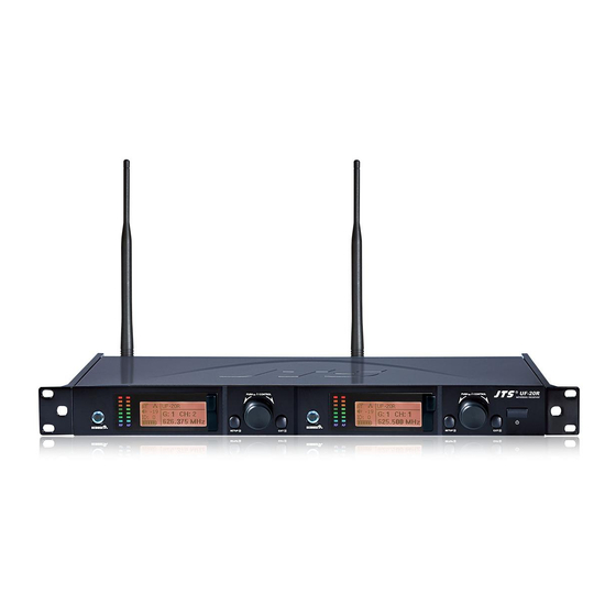
UF-20R / UF-20S / JSS-20 / UF-20TB
Professional Wideband (75MHz)
True Diversity System
59508-072-02
PROFESSIONAL CO., LTD
No.148, 9th Industry Road, Ta-Li Industrial
Park, Taichung City 41280, Taiwan (R.O.C.)
Tel: 886-4-24938803 Fax: 886-4-24914890
Email: jts@jts.com.tw
www.jts.com.tw
UF-20R / UF-20S /
JSS-20 / UF-20TB
Product manual
Advertisement
Table of Contents

Related Manuals for JTS UF-20R


Summary of Contents for JTS UF-20R
- Page 1 UF-20R / UF-20S / JSS-20 / UF-20TB UF-20R / UF-20S / JSS-20 / UF-20TB PROFESSIONAL CO., LTD Product manual No.148, 9th Industry Road, Ta-Li Industrial Park, Taichung City 41280, Taiwan (R.O.C.) Professional Wideband (75MHz) Tel: 886-4-24938803 Fax: 886-4-24914890 True Diversity System Email: jts@jts.com.tw...
-
Page 2: Warranty Description
......9 1. Be sure to put the warranty label indicating purchase date on the bottom of equipment to ensure your .............. 9 4-1 Receiver // UF-20R/UF-20S interest in maintenance and service............15 2. Product warranty, starting on the purchase date indicated on “warranty label”, will last for one year; if 4-2 Handheld Transmitter // JSS-20 the equipment does not have “warranty label”, the warranty period is 15 months from the manufac-... - Page 3 The panel Lock-On function prevents tampering and RF interruption NEWEST FEATURE: • • Together with JTS various music instrument mics, headset mics and tie clip mics this bodypack REMOSET now sends not only the frequency data but also transmitter’ s RF power, is versatile for all applications.
-
Page 4: Specification
3. Specification 3-1-1. Dual Channel Wideband True Diversity Receiver // UF-20R 3-1-2. Single Channel Wideband True Diversity Receiver // UF-20S Frequency Preparation....PLL Synthesized Control Frequency Preparation....PLL Synthesized Control Frequency Setting......JTS patented obstacles-free RF REMOSET Frequency Setting......JTS patented obstacles-free RF REMOSET Carrier Frequency Range.. - Page 5 3-2 Professional Wideband Handheld Transmitter // JSS-20 3-4 Optional Charger For JSS-20 & UF-20TB & PS-20 Frequency Preparation....PLL Synthesized Control Model No....... CH-2 ( 2-Slot Charger ) Carrier Frequency Range..UHF 470~960 MHz Input........... AC 100~240V, 0.4A max Bandwidth.......... 60~75MHz Wideband Output........
-
Page 6: Headset Microphone
Headset Microphone Ear-hook Microphone Model No....... CM-214i CM-214Ui CM-214ULi Model No....... CM-801/CM-804i CM-8015/CM-825i Connector....... 801C4 801C4 801C4 Connector......801C4 (4P Mini XLR) 801C4 (4P Mini XLR) Frequency Response..60~15,000 Hz 50~18,000 Hz (4P Mini XLR) (4P Mini XLR) (4P Mini XLR) Frequency Response.. -
Page 7: Parts Identification & Accessories
Power : Power on: Push the Power button to turn on Power off: Push and hold the Power button until “Power Off ” shows on the LCD EXIT key: Push EXIT to cancel the selection and exit the menu when the UF-20R is in the “Setting Menu. ”... - Page 8 4-1-2. Description of receiver LCD display Display color: : Panel Lock On activated on receiver. Red: (1) No RF signal is received from any transmitter, and the LCD shows: : It indicates antenna A or B is receiving signal; is shown when no signal is received from a microphone.
- Page 9 4-1-3. Back panel // UF-20R 4-1-4. Back panel // UF-20S POWER: AC power, 100 ~ 240VAC Power receptacle: connect to power supply (DC12V/1000mA) AC power outlet(for cascading): it allows power connection to next receiver with an Balanced XLR MIC output extension AC power cable.
-
Page 10: Panel Functions
4-2 Buttons and LCD Displays of UHF PLL Handheld Transmitter // JSS-20 4-2-1. Panel functions LCD display SET: set and save handheld transmitter 、 : up and down buttons to select the desired function of the handheld device. Power (1) Handheld transmitter on Power on: push the Power button. - Page 11 4-3 Buttons and LCD Displays of UHF PLL Body-Pack Transmitter // UF-20TB 4-3-2. Description of LCD display 4-3-1. Panel functions Transmission Power: Hi (High) and Lo (Low) LCD display User Name Battery level Indicate current Group and current Channel Red: battery low; replace battery Frequency: it shows the RF frequency REMOSET indicators Battery level: in 5 levels...
- Page 12 4-4 Optional 2-Slot Charger / 8-Slot Charger // CH-2/CH-8 4-5 Optional Condenser Microphone Lavaliere Microphone // CM-501 / CM-201i / CM-125i LED Indicator Full Charged / Standby:Green Charging:Flash Green Clip Fault:Flash Red 4 Pin Mini XLR *Charging Time:3 hours Windscreen CM-501 CM-201i CM-125i...
- Page 13 Headset Microphone // CM-214i / CM-214Ui / CM-214ULi / CM-235i / Ear-hook Microphone // CM-801 / CM-804i / CM-8015 / CM-825i CX-504 Boom Gooseneck Adjustable Headband Adjustable headband Adjustable ear hook Headband Detchable Cable 4 Pin Mini XLR Cable Clip CM-801 Windscreen Windscreen...
- Page 14 Compatible Instrument Microphone // CX-500 / CX-500F / CX-520 / 4-6-1. Accessories for UF-20R CX-508W / CX-516W Gooseneck AC power cable * 1 Clip BNC/BNC RF extension cable for cascading * 2 Bracket Front antenna signal cable Option Volume Control...
-
Page 15: Connection Method
AC/DC power adapter * 1: Switching power adapter Audio cable: XLR or Ø 6.3mm audio cable, one end connects to audio output of UF-20R “AF AC IN: AC100~240V/50~60Hz OUTPUT BALANCED”, while the other end connects to audio input of a mixer or an ampli- DC OUT: DC12V/1000 mA fier. - Page 16 5-1-2. Receiver connection method // UF-20S 5-2 Cascading of AC power cable and antenna (UF-20R Only) 1. UF-20S output to a mixer or an amplifier: It is allowed to cascade power and antennas for 10 units. Audio cable: XLR or Ø 6.3mm audio cable, one end connects to audio output of UF-20S “AF OUTPUT BALANCED”, while the other end connects to audio input of a mixer or an ampli-...
-
Page 17: Operation
(1)For receiver settings, please see: “6. Device ID” and “7. Microphone Setting” of 6-1 Operation settings for Wideband True Diversity Receiver. *When using the REMOSET function of UF-20R, it is recommended to carry out RE- (2)For handheld transmitter settings, please see: “5. Device ID” and “6. Remoset MOSET one by one. -
Page 18: Menu Setting
6-1-3. Menu setting Push and hold the SETUP button for 2 seconds to enter the menu. (2) Rotate the switch to select a group “G:” from 1 to 15. Setup Group (1) Turn the rotary switch clockwise or counterclockwise to select the desired function. Push the rotary switch to save the selected value. - Page 19 #2. Clear Group: delete a group defined by us er #2. Result List: view the scan result list 1. Custom Group 1. All Groups (1) Rotate the rotary switch to “2. Clear Group. ” Push the 2. Clear Group Rotate the rotary switch to “2. Result List. ” Push the rotary 2.
- Page 20 6. Device ID: define the ID code of device (3. LowCut: base attenuation 5. Squelch 1. Sensitivity (1) Rotate the rotary switch to “6. Device ID. ” Push the rotary 6. Device ID Rotate the rotary switch to “3. LowCut. ” Push the rotary 2.
- Page 21 (2) Rotate the rotary switch to select and push the switch to 9. Equalizer: equalizer settings 9. Equalizer check the selection; REMOSET only synchronizes on (1) Rotate the rotary switch to “9. Equalizer. ” Push the rotary a. Output Level b.
- Page 22 Push the rotary switch to confirm the selection, and the firmation, select SETUP to save the setting; “Lock ON”can Lock ON UF-20R screen jumps to the next character to be selected. Select lock up the keypad of the receiver panel and prevent...
-
Page 23: Menu Function Setting
6-2 Handheld transmitter system operation setting // JSS-20 6-2-1 Power button 6-2-2 Menu function setting: (1) Turn on the power press SET and it will enter into menu function Power On: press POWER setting after two seconds. (1) Press ▲、▼ Select the desired item. Press SET to enter into the pre-set option. - Page 24 3.Sensitivity 6. Remoset 1. Frequency 5. Device ID 2. Group/Channel 6. Remoset (1) Press ▲、▼ to “3. Sensitivity. ” Press SET to enter into the Press ▲、▼ to select “6.Remoset” function. Press SET to enter 3. Sensitivity 7. RF Power setting screen.
- Page 25 8. Contrast b. Reset 5. Device ID 9. Light Time 6. Remoset a. User Name (1) Press ▲、▼ to select“8. Contrast. ” Press SET to enter into the Press ▲、▼ to “b. Reset” and select SET to enter the screen setting. 7.
-
Page 26: Function Setting Menu
6-3 Body-pack transmitter system operation setting // UF-20TB 2. Group / Channel Frequency Group/Chan (1) Press ▲、▼ to select “2. Group / Channel. ” Press SET to enter into the 6-3-1 To turn on UF-20TB body-pack transmitter (diagram 5) Sensitivity setting screen. - Page 27 5. Low Cut 6. Remoset: to turn on/off the REMOSET Frequency Device ID Group/Chan Remoset (1) Press ▲、▼ to select“Low Cut. ” Press SET to enter into the “Low Cut” (1) Press ▲、▼ to select REMOSET function. Press SET to enter into Sensitivity RF Power setting screen.
- Page 28 9. Light Time: the setting of the backlight time 12. Key Lock: setting of the keypad lock Device ID User Name Remoset Reset (1) Press ▲、▼ to the keypad lock. Press SET to enter into “key Lock” RF Power KeyLock (1) Press ▲、▼...
-
Page 29: Installation Of Condenser Microphones
Attach the detachable cable to a suitable place by a cable clip. UHF PLL Transmitter (3) Instrument Microphones The system is compatible with JTS various instrument microphones. For detail please refer to user’ s manuals of these microphones. Professional Wideband True Diversity System (75MHz) -
Page 30: Product Notes
(1) To get the best signal performance, please keep at least 3 meters between a receiver and a (1) JTS offers wireless systems in a selection of bands that conform to the different government regulations of specific nations or geographic regions. These regulations help limit radio transmitter.
Need help?
Do you have a question about the UF-20R and is the answer not in the manual?
Questions and answers