
Related Manuals for Messoa NCR875E(H)


Summary of Contents for Messoa NCR875E(H)
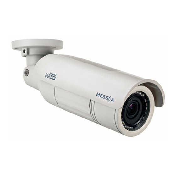
- Page 1 Bullet Network Camera NCR875E(H)/NCR875PRO(H) User Manual 2012-10 A2...
-
Page 2: Safety Notice
Safety Notice „ Make sure the supplied voltage meets the power consumption requirements of the camera before powering the camera on. Incorrect voltage may cause damage to the camera. „ The camera should be protected from water and moisture, excessive heat, direct sunlight and cold. „... -
Page 3: Ce Compliance Statement
CE Compliance Statement This equipment complies with the following requirements of the EMC Directive 2004/108/EC for CE Marking: EN 55022: 2006 + A1: 2007, EN 61000 and EN 55024 FCC Compliance Statement If the declaration of conformity markings are present on the equipment, the following statements apply: Tested to comply with FCC standards for HOME OR OFFICE USE. -
Page 4: Table Of Contents
Table of Contents Table of Contents Safety Notice ....................... 2 Operating Notice ....................2 CE Compliance Statement ..................3 FCC Compliance Statement ..................3 WEEE ........................3 1. Overview ....................6 1.1 Package Contents .................... 6 1.2 Hardware Overview ..................6 1.2.1 Part Names ...................... - Page 5 Table of Contents 4.2.7 Privacy Zone ......................29 4.2.8 ePTZ .........................30 4.3 Network ....................... 31 4.3.1 Basic .........................31 4.3.2 FTP ........................32 4.3.3 SMTP ........................32 4.3.4 NTP ........................34 4.3.5 RTSP .........................34 4.3.6 ONVIF .......................35 4.4 System ......................36 4.4.1 Date and Time ....................36 4.4.2 Time Stamp .......................36 4.4.3 Firmware ......................37 4.4.4 User Management ....................39...
-
Page 6: Overview
1. Overview 1. Overview 1.1 Package Contents The package includes these items: „ Bullet Network Camera „ CD-ROM (User manual and IP Finder utility) „ Quick Start Guide „ Guide Pattern „ Insulation caps „ Self-tapping Screw (TP4 x 31mm) „... -
Page 7: Connectors
1. Overview Front Cap Rear Cap 5. microSD/SDHC Card Slot: Insert a microSD/SDHC card to the slot for recording and storage. 6. Far/Near Control: Loosen the control to adjust the picture sharpness. 7. Tele/Wide Control: Loosen the control to adjust the image view. 8. -
Page 8: Dimensions
1. Overview 7. RS-485+/-: Reserved. 8. GND: Grounding. 9. Alarm IN 1/2: Connects to device that triggers alarm signals which range between DC +3.3 and 6 Volts for High level activation, and under +1 Volt for Low level activation. 1.2.3 Dimensions 289mm (11.36”) 174mm (6.86”) 281mm (11.05”) -
Page 9: Specifications
1. Overview 1.3 Specifications Ethernet 10Base-T/100Base-TX IPv4, TCP/IP, UDP, HTTP, SMTP, DNS, DHCP, NTP, Protocol FTP, RTP,RTSP, ICMP, UPnP IEEE 802.3af, Class 3 Image System Browser IE browser 6.0 or above 1/2.7" image sensor optimized for low-light Image Sensor ONVIF performance Compression Triple Streaming: H.264 / MPEG4 / Motion JPEG... -
Page 10: Installation
2. Installation 2. Installation Warning Caution Note The front and rear cap should NOT be removed over 30 minutes during installation. Otherwise, the desiccant will absorb too much moisture and thus cause vapor. 2.1 Inserting Memory Card 1. Loosen the two sunshield fixing screws and remove the sunshield. 2. -
Page 11: Adjusting The View And Focus
2. Installation Insulation Cap Rubber Pad 2.3 Adjusting the View and Focus Refer to the figure below, loosen the screws as needed to adjust the camera to desired angel. 1. Loosen the screw to rotate the pipe segment. 2. - Page 12 2. Installation TELE/WIDE Control NEAR/FAR Control NCR875E(H)/NCR875PRO(H) User Manual...
-
Page 13: Network Connection And Configuration
3. Network Connection and Configuration 3. Network Connection and Configuration 3.1 Network Connection Types There are many different ways that you can connect the camera to your network, depending on your applications requirements. You should always set the camera’s network settings according to your network configurations. - Page 14 3. Network Connection and Configuration Caution Note The LAN port of the camera supports auto MDI/MDIX (Medium dependent interface crossover) so there is no need for an uplink port or the use of a cross-over cable. Assign an IP address to your camera following your network IP allocation policy. You can manually specify the IP address or allocate the IP address automatically using a DHCP server, if available on your network.
-
Page 15: Accessing The Camera For The First Time
3. Network Connection and Configuration If your camera is configured to use a non-standard HTTP port, then you have to forward that port accordingly. 3.2 Accessing the Camera for the First Time The camera comes with a web-based setup utility, allowing you to view the video of the camera and configure the camera for optimal use in your environment. - Page 16 3. Network Connection and Configuration If the message of “Reply from…” appears, it means the connection is established. Step 4: Accessing the Camera via IE Browser Open the IE browser and enter the IP address of the camera in the URL field. The default is 192.168.1.30. When prompted for login, enter the user name and the password.
-
Page 17: Using "Ip Finder" To Manage Cameras
3. Network Connection and Configuration Upon successful login, you will see the live view screen shown below, which is taken from NCR875PRO(H) for series introduction. 3.3 Using “IP Finder” to Manage Cameras IP Finder is a management tool included on the product CD. It is designed to manage your network cameras on the LAN. - Page 18 3. Network Connection and Configuration The Tool menu of the IP Finder allows you to perform these tasks: „ Search Network: This option allows you to search the cameras on the network. „ Set Master ID and Password: Allows you to set a master ID and password for managing the cameras with IP Finder.
- Page 19 3. Network Connection and Configuration „ Network Information: Allows you to configure the camera’s network settings. NCR875E(H)/NCR875PRO(H) User Manual...
-
Page 20: Web-Based Interface
4. Web-based Interface 4. Web-based Interface 4.1 Overview 4.1.1 Main Screen After you log in to the camera’s web-based control utility, you will first see the live view screen of the camera. The screen below is taken from NCR875PRO(H) for series introduction. Live view video Camera name Snapshot button... -
Page 21: Setup Menu
4. Web-based Interface 4.1.2 Setup Menu The Setup options are categorized into five groups: Image, Network, System, Event and Recording. Clicking the name will expand its sub-menu. See the ensuing sections for more information. 4.1.3 Applying Settings Each configuration page provides a Save button. Settings are applied right after you press the Save button. And the browser will refresh to load the latest setting or otherwise pop up the “Save OK”... - Page 22 4. Web-based Interface Camera Name Settings „ Enter a descriptive name of the camera. Note that if you want to make the camera ONVIF compliant (see Network > ONVIF ), no space is allowed in the camera name. H.264 Codec Settings „...
- Page 23 4. Web-based Interface Refer to the tables below for selectable codec types for each streaming: NCR875PRO/NCR875PROH Streaming Combination Primary Secondary Third Codec Resolution Codec Resolution Codec Resolution 1080P H264 MPEG4 2CIF MJPEG SXVGA MJPEG 720P SVGA H264 MPEG4 2CIF MJPEG 1080P MJPEG H264...
-
Page 24: Exposure
4. Web-based Interface „ VERTICAL: Flips the images vertically. „ BOTH: Flips the images vertically and horizontally. Rate Control Choose a bit rate control to manage your bandwidth usage. „ Variable Bit Rate (VBR): VBR keeps the video stream quality as constant as possible by varying bit rate. This mode ensures high quality image for motion scene and is often selected when image quality demands priority. - Page 25 4. Web-based Interface • Object Targeted: This option meters the exposure based on the targets you specify. When this option is selected, define your target by clicking squares displayed on the image and then press Save Spot Window to save the setting. „...
- Page 26 4. Web-based Interface Shutter Settings: „ Slow Shutter: Set the exposure time from a set of fixed shutter speeds. „ Manual Exposure Time: Manually input a desired exposure time. Gain Settings: „ Max. Gain: Specify the maximum amount of amplification applied to the image. A high level of gain allows images to be viewable in very low light, but will increase the image noise.
-
Page 27: White Balance
4. Web-based Interface 4.2.3 White Balance Select a white balance mode according to external light condition for the best color temperature. „ Auto White Balance: Use this option when there is no special lighting in the environment. The camera will automatically adjust the color temperature according to the light conditions and the sensitivity you specify. -
Page 28: Basic Setting
4. Web-based Interface 4.2.4 Basic Setting The Basic Setting allows you to specify a frequency and adjust the basic image settings to optimize your video image. „ Frequency: Select an appropriate frequency to reduce the flicker on the image. “50 Hz” and “60 Hz” are provided Frequencies settings will affect the Max. -
Page 29: Smart Encoding
4. Web-based Interface 4.2.5 Smart Encoding On the Smart Encoding page you can specify a specific region of the video as more important, i.e., a region of interest (ROI). When a ROI is specified, the camera will assign a higher number of bits to the ROI area to deliver better video quality than non-ROI areas. -
Page 30: Smart Focus
4. Web-based Interface 4.2.6 Smart Focus In addition to observing the live view image to see if focus is achieved, you can also enable Smart Focus to help you verify if focus is locked. If this function is enabled, whenever focus is achieved, the focus window turns green. -
Page 31: Eptz
4. Web-based Interface 4.2.8 ePTZ Using the ePTZ function, you can use the pan, tilt and zoom controls to steer the camera to a desired position and focus on desired close-up areas, without moving the camera physically. On the main screen, a PTZ button appears. After you click the ePTZ button, an ePTZ control panel will shows up where you can click the corresponding indicators to perform desired operations: •... -
Page 32: Network
4. Web-based Interface 4.3 Network 4.3.1 Basic „ DHCP: If there is a DHCP server on the network and you enable this option, the server will automatically assign an IP address and related information to the camera. Caution Note If there is no DHCP server on your network or you prefer to manually assign an IP address to the camera, leave the DHCP checkbox blank. -
Page 33: Ftp
4. Web-based Interface „ IP Address & Subnet Mask: If the DHCP function is not enabled, you have to assign an IP address with the subnet mask to the camera. „ Default Gateway: Enter the IP address of the gateway if required. Please contact your network administrator whether you need to set up the gateway. - Page 34 4. Web-based Interface „ My Server Requires Authorization: If your SMTP server requires authorization to send emails, enable this option. „ SMTP Server IP: Enter the IP address of the SMTP server. „ User Name: Enter the user name to log on to the SMTP server. „...
-
Page 35: Ntp
4. Web-based Interface 4.3.4 NTP If you want the camera to synchronize its time clock with an NTP (Network Time Protocol) sever, configure the NTP server settings here. „ NTP Server: Enter the IP address or the domain name of the NTP server to synchronize with. „... -
Page 36: Onvif
4. Web-based Interface Stream MJPEG Primary rtsp://192.168.1.30:8555/mjpeg MJPEG Third rtsp://192.168.1.30:8558/mjpeg H.264 Primary rtsp://192.168.1.30:8557/h264 H.264 Secondary rtsp://192.168.1.30:8556/h264 MPEG4 Primary rtsp://192.168.1.30:554/mpeg4 MPEG4 Secondary rtsp://192.168.1.30:8554/mpeg4 *Replace the IP address and the port number with the camera’s settings if otherwise configured. 4.3.6 ONVIF ONVIF is a standard that ensures interoperability between IP-based physical security products regardless of the manufacturers. -
Page 37: System
4. Web-based Interface 4.4 System 4.4.1 Date and Time Current Time Displays the current date and time of the camera. Date and time will be updated after you configure new settings in the New Time section and click Save to apply the settings. New Time You can set the camera time by one of the following methods: „... -
Page 38: Firmware
4. Web-based Interface „ Enable Date and Time Stamp: Check this box to enable the date and time stamp on images/video clips; to disable this function, uncheck the box. „ Date Format: Select the desired date format for the time stamp. 4.4.3 Firmware Current Version Description: Displays the current version of the firmware. - Page 39 4. Web-based Interface 4. Wait about 20~60 seconds until the file is successfully updated. Once the update is completed, the browser will show a message reads “Firmware update successful”. Then it will take 60 seconds to restart the camera. 5. The utility will automatically go back to live view screen after firmware has been updated successfully. You can also perform these tasks on the Firmware page: „...
-
Page 40: User Management
4. Web-based Interface 4.4.4 User Management The User Management page allows you to manage user accounts and access privileges. User List Displays the list of current user accounts of the camera. To delete a user account, select the unwanted user account from the list and then click Delete User. -
Page 41: Log
4. Web-based Interface 4.4.6 Log This page displays detailed information about the camera’s operations and activities, including all the login and alarm records. „ Clear Log File: Click the button to clear the log cache. „ Download Log File: Click the button to save the current log into a text file. When a dialog window shows up, click the Save button to locate the directory where the logfile.txt is to be stored. -
Page 42: Audio
4. Web-based Interface 4.4.7 Audio „ Audio Receiving: If a microphone is connected to the camera, you can select ON to allow the camera to record the audio and transmit to your PC. This enables the camera to pick up sounds in the background. „... -
Page 43: Motion Detection
4. Web-based Interface When an event occurs, it triggers an alarm and the camera will take a pre-defined action, e.g., sending a recorded video clip or JPEG files to a designated server. With this camera, an event can be triggered by external alarm devices or the camera’s detection mechanism, including motion, blur, audio and Ethernet detection. -
Page 44: External Alarms
4. Web-based Interface Select OFF to disable the motion detection Motion Area Setting „ Motion area setting: Click target squares displayed on the screen to define detection areas; once configured, click Save Motion Area to save settings . Action Specify the action to be taken when an alarm is triggered upon motion detection: „... -
Page 45: Face Detection
4. Web-based Interface Caution Note To perform a video recording, you must select MJPEG codec for one of the streams. 4.5.3 Face Detection With the Face Detection enabled, one or multiple square frames will cover the faces detected in the scene. You can specify a particular area by clicking and dragging your mouse, and then click the Save Window button. -
Page 46: Blur Detection
4. Web-based Interface Action Select the radio buttons for actions in response to the pictures saved to FTP server, SMTP server or SD card if a face detection alarm is triggered. OFF is set by default. „ OFF: No action will be taken (but an alarm is logged). „... -
Page 47: Audio Detection
4. Web-based Interface 4.5.5 Audio Detection With the Audio Detection enabled, when the camera detects any sound, the camera will generate an alarm and then take a specified action. Configuration „ Audio Sensitivity: Specify the camera’s sensitivity level to the audio signal. The higher the sensitivity, the lower the volume is required to set off an alarm. -
Page 48: Event Management
4. Web-based Interface Configuration „ Trigger an Alarm When Ethernet is Disconnected: Select whether to disable/enable this function. Action Specify the action to be taken when an alarm is triggered upon audio detection: „ OFF: No action will be taken, but an alarm will be logged. „... -
Page 49: Settings - Video File
4. Web-based Interface 4.6.1 Settings – Video File Configure the duration and format of video to be recorded when an alarm is triggered. Basic Settings „ AVI Duration for FTP Server: Select recorded video duration in seconds for the FTP server. „... -
Page 50: Settings - Smtp
4. Web-based Interface • AVI files: The camera will record AVI files and upload to the FTP sever. For the duration and AVI format, see Recording > Setting > Video File. 4.6.3 Settings – SMTP SMTP Networking Displays the current SMTP settings, which are specified via Network > SMTP. Storage Setting „... -
Page 51: Sd Card Storage Format Selection
4. Web-based Interface 4.6.4 SD Card Storage Format Selection Storage Setting „ File Format: Specify the format of the video/picture to be saved to the SD card when an event is triggered. „ Capacity/Usage: Shows the card capacity and the space usage percentage. „... -
Page 52: Period Setting
4. Web-based Interface Besides, users can also just launch the Windows Explorer to access SD card. The same, users are supposed to enter the FTP address (ftp://192.168.1.30 by default) in the address field and finish login process. Then you can directly get into the directory. 4.6.5 Period Setting The Period Setting allows you to schedule video recordings at specified times. - Page 53 Corporate Headquarters No.8, Wuquan Road, New Taipei Industrial Park, Wugu District, New Taipei City 24886, Taiwan, R.O.C. Tel: +886-2-2298-3908 Fax: +886-2-2298-3909 E-mail: info@messoa.com USA Office 13611 12th St, Unit B Chino, CA 91710, USA Tel: +1-909-590-5955 Fax: +1-909-590-2374 E-mail: info@messoa.com Greater China Office Room 301, Yuanzhong Office Building, No.2007...
Need help?
Do you have a question about the NCR875E(H) and is the answer not in the manual?
Questions and answers