Dell 5000 Series Installation And Operation Manual
Hide thumbs
Also See for 5000 Series:
- Service manual (40 pages) ,
- Setup and specifications (29 pages) ,
- Quick start manual (2 pages)
Table of Contents
Advertisement
Quick Links
See also:
Service Manual
Advertisement
Table of Contents

Related Manuals for Dell 5000 Series


Summary of Contents for Dell 5000 Series
-
Page 1: Installation And Operation Manual
Dell Edge Gateway 5000 Series Installation and Operation Manual Regulatory Model: N01G\N02G Regulatory Type: N01G001\N02G001... - Page 2 © 2016 Dell Inc. All rights reserved. This product is protected by U.S. and international copyright and intellectual property laws. Dell and the Dell logo are trademarks of Dell Inc. in the United States and/or other jurisdictions. All other marks and names mentioned herein may be trademarks of their respective companies.
-
Page 3: Table Of Contents
Industry Canada Statement............13 Powering on the Dell Edge Gateway ........16 Mounting the Dell Edge Gateway on the wall....16 Mounting the Dell Edge Gateway on a DIN rail....19 Inserting a micro-SIM card and activating your mobile broadband..............22 Removing the micro-SIM card............24... - Page 4 Setting up the Power Module............. 43 Power module — Connecting a battery......47 Specifications - Power Module..........49 8 Enclosure Overview..............52 Features....................53 Setting up the Enclosure.............. 54 Specifications - Enclosure............61 9 Setting up the ZigBee Dongle ............ 63 10 Contacting Dell................65 5000 Series...
-
Page 5: Overview
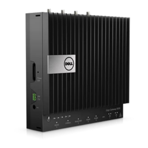
The Dell Edge Gateway 5000/5100 series allows you to connect (wired or wireless) to network enabled devices and manage them remotely in your existing network ecosystem. The system can be either mounted on the wall using the Dell approved wall mount kit or mounted into your existing rack infrastructure using the DIN-rail mounting bracket. -
Page 6: System Features
System Features Feature USB 2.0 port For USB 2.0 devices USB 2.0 port For USB 2.0 devices HDMI port Connect a Monitor or another HDMI‑in enabled device. Provides video and audio output. Wi-Fi antenna port (port four) Connect an antenna to increase the range and strength of the Wi-Fi signals. - Page 7 Feature Mobile broadband antenna port Connect an antenna to increase the range (port two) and strength of the mobile broadband signals. Micro-SIM card slot Insert a micro-SIM card to connect to a mobile broadband network. Mobile broadband antenna port Connect an antenna to increase the range (port one) and strength of the mobile broadband signals.
-
Page 8: System Leds
Feature 23. I/O expansion port Connect an external expansion module for additional I/O ports. Topics: • System LEDs • DIP switches System LEDs Feature Serial port status LED Provide the status of the serial port connection. CANbus port status LED Provide the status of the CANbus port connection. -
Page 9: Dip Switches
Feature 10. Wireless status LED Indicates the wireless connectivity status and network activity. Bluetooth status LED Indicates the bluetooth status and activity. 12. Cloud connection status LED Indicates the cloud connection status. DIP switches Feature RS422/RS485 port toggle switch Toggle between RS422 or RS485 standard RS422/RS485 port resistor Enable/disable the differential termination switch... -
Page 10: Setting Up Your Dell Edge Gateway
WARNING: When installing the Gateway, the responsible party or integrator shall use the AC Adapter provided with the Dell Edge Gateway, or connect to a 24Vac or 24Vdc power source already present as part of the clients installation. -
Page 11: Professional Installation Instructions
Use only the antenna(s) which have been approved by the applicant. Non-approved antenna(s) may produce unwanted spurious or excessive RF transmitting power which may lead to a violation of FCC/IC limits and is prohibited. Installation procedure Please refer to user’s manual for the detail. Setting up your Dell Edge Gateway... -
Page 12: Instructions D'installation Professionnelles
This device complies with Part 15 of the FCC Rules. Operation is subject to the following two conditions: (1) This device may not cause harmful interference, and (2) this device must accept any interference received, including interference that may cause undesired operation. Setting up your Dell Edge Gateway... -
Page 13: Industry Canada Statement
US model. Per FCC regulation, all WiFi product marketed in US must fixed to US operation channels only. Industry Canada Statement This device complies with Industry Canada license-exempt RSS standard(s). Operation is subject to the following two conditions: this device may not cause interference, and Setting up your Dell Edge Gateway... - Page 14 20cm between the radiator & your body. Déclaration d'exposition aux radiations: Cet équipement est conforme aux limites d'exposition aux rayonnements IC établies pour un environnement non contrôlé. Setting up your Dell Edge Gateway...
- Page 15 (c.-à-d., qu’ils ont la priorité) pour les bandes 5250-5350 MHz et 5650-5850 MHz et que ces radars pourraient causer du brouillage et/ou des dommages aux dispositifs LAN-EL. Topics: • Powering on the Dell Edge Gateway Setting up your Dell Edge Gateway...
-
Page 16: Powering On The Dell Edge Gateway
RS422/R485 ports. Mounting the Dell Edge Gateway on the wall You can mount the Dell Edge Gateway on a wall by using mounting brackets. The brackets secure the Dell Edge Gateway to the wall. Secure the two mounting brackets to the rear of the Dell Edge Gateway by using four screws. - Page 17 Drill four holes in the wall that correspond to the holes in the mounting bracket, then place the Dell Edge Gateway against the wall and align the holes in the mounting brackets with the holes in the wall. Setting up your Dell Edge Gateway...
- Page 18 Tighten the screws to secure the Dell Edge Gateway to the wall. Setting up your Dell Edge Gateway...
-
Page 19: Mounting The Dell Edge Gateway On A Din Rail
Mounting the Dell Edge Gateway on a DIN rail The Dell Edge Gateway can be mounted on a DIN rail. The DIN rail bracket mounts to the back of the Dell Edge Gateway. Align the screw holes on the DIN rail mount to the back of the Dell Edge... - Page 20 Pull down on the tab to release the latch on the DIN rail mount. Mount the Dell Edge Gateway on a DIN rail. Setting up your Dell Edge Gateway...
- Page 21 Secure the Dell Edge Gateway by pressing the latch. Setting up your Dell Edge Gateway...
-
Page 22: Inserting A Micro-Sim Card And Activating Your Mobile Broadband
Using a paper clip or SIM eject tool eject the micro-SIM card tray. Place the micro-SIM card on the tray. CAUTION: Ensure that the micro-SIM card is aligned as shown in the image. Close the micro-SIM card tray. Setting up your Dell Edge Gateway... - Page 23 #nmcli con add type gsm ifname ttyACM3 con-name <connection name> apn <apn> user <user name> password <password> Connect to the mobile network: #nmcli con up <connection name> To disconnect from the mobile network: #nmcli con down <connection name>. Wind River OS Setting up your Dell Edge Gateway...
-
Page 24: Removing The Micro-Sim Card
Using a paper clip or SIM eject tool eject the micro-SIM card tray. Remove the micro-SIM card out of the micro-SIM card tray. Replace the micro-SIM card tray into the Gateway. Setting up your Dell Edge Gateway... -
Page 25: Setting Up Your Operating System
For more information on setting up your Wind River operating system, see http://www.windriver.com/support. Power on the Gateway. The Wind River splash screen is displayed after the Dell Edge Gateway boots completes POST. The operating system will take around twenty seconds to complete the loading process. - Page 26 The Wind River operating system is setup. Setting up your operating system...
-
Page 27: Specifications - Gateway
• 64 GB SSD Dimensions Height 228.4 mm (8.99 inches) Width 216 mm (8.50 inches) Depth • Dell Edge Gateway 5000: 64.20 mm (2.52 inches) • Dell Edge Gateway 5100: 74.50 mm (2.93 inches) Memory Type LPDDR3 Speed 1600 MHz... - Page 28 Power adapter input voltage/current 19.5 VDC / 3.33A Environmental requirements Ingress Protection Rating IP50 Temperature range: Dell Edge Gateway 5000 Operating (with a maximum temperature gradation of 15°C • 0°C to 50°C (32°F to 122°F) when (59°F) per hour) connected to a 24V AC/DC power source.
- Page 29 Environmental requirements Dell Edge Gateway 5100 • 0°C to 70°C (32°F to 158°F) when connected to a 24V AC/DC power source. • 0°C to 40°C (32°F to 104°F) when connected to a power adapter. NOTE: The maximum operating temperature is derated 1°C/305m...
-
Page 30: O Module Overview
The I/O module allows you to install a PCIe x1 card and adds additional ports to your Dell Edge Gateway. NOTE: The power module is required to be installed with the Dell Edge Gateway to enable and use the I/O expansion module. Topics: •... -
Page 31: Features
Features I/O Module Overview... -
Page 32: Setting Up The I/O Module
Push both the top and bottom release- latch to disconnect the power module from the Dell Edge Gateway. I/O module expansion Connect the I/O module to the Dell Edge connector and guide pin Gateway. Power status light Indicates the power state of the I/O module and the Dell Edge Gateway. - Page 33 Install the PCIe card on the PCIe expansion card slot on the I/O Expansion Module. Replace the cover on the I/O Expansion Module. NOTE: Replace the dust-caps on any unused ports and connectors. I/O Module Overview...
- Page 34 Tighten the screw that secures the cover to the I/O Expansion Module. Remove the dust-cap covering the I/O Module expansion port on the Dell Gateway connector. Align the I/O Module guide pin to port on the Dell Edge Gateway. I/O Module Overview...
- Page 35 Slide the I/O Module until it is fully seated into the Dell Edge Gateway. 10 Lock the top and bottom latches to secure the module to the Dell Edge Gateway. I/O Module Overview...
- Page 36 Install the Dell Edge Gateway and the I/O Module along with the Power Module at a desired location using wall-mount bracket or the DIN rail mount. Wall Mount Bracket DIN Rail Mount 12 Connect to a power source and press the power button.
-
Page 37: Specifications - I/O Module
Power Module. NOTE: The power adapter and sealed lead-acid battery is sold separately. NOTE: The power module is required to be installed with the Dell Edge Gateway to enable and use the I/O expansion module. Specifications - I/O Module Dimensions Height 207.60 mm (8.17 inches) - Page 38 Power requirements Phoenix connector input voltage/ 24 VAC (50 Hz–60 Hz) or 24 VDC / 15A current Power adapter input voltage/current 19.5 VDC / 6.67A Battery connector port 12 VDC / 15A Environmental requirements Ingress Protection Rating IP50 NOTE: Enclosure meets IP50 with the pre-installed PCIe blank bracket.
- Page 39 Environmental requirements Relative humidity (maximum): Operating (with maximum 10% to 90% (non-condensing) humidity gradation of 10% per hour) Non-operating ((with maximum 5% to 95% (non-condensing) humidity gradation of 10% per hour) Altitude (maximum, unpressurized): Operating -15.2m to 5000m (-50ft to 16,404ft) NOTE: The maximum operating temperature is derated 1°C/305m...
- Page 40 System ambient Maximum Maximum Maximum after altitude supported power supported power supported power derating (°C) dissipation (W) for dissipation (W) for dissipation (W) for 85° C or above still 70° C still air rated 55°C still air rated air rated PCIe PCIe cards PCIe cards cards...
-
Page 41: Power Module Overview
Power Module Overview The power module allows you to connect additional power sources to your Dell Edge Gateway. The power module allows you to connect to all three power sources, that is, the 24V AC/DC, 19.5 VDC, and a battery. -
Page 42: Features
Features Feature Top release-latch Push both the top and bottom release- latch to disconnect the power module from the Dell Edge Gateway. Power status LED Indicates the power‑state of the power module and the Dell Edge Gateway. Power Module Overview... -
Page 43: Setting Up The Power Module
Gateway and disconnect the power cable. NOTE: The power module is required to be connected with the Dell Edge Gateway to enable and use the I/O expansion module. Remove the dust-cap covering the Power Module expansion port on the Dell Gateway connector. - Page 44 Align the Power Module guide pins to the power module port on the Dell Edge Gateway and slide the Power Module until it is fully seated in the Dell Edge Gateway Ensure the top and bottom latches are locked to secure the module to the...
- Page 45 Install the Dell Edge Gateway and the Power Module at a desired location using wall-mount bracket or the DIN rail mount. Wall-mount bracket Power Module Overview...
- Page 46 DIN rail Connect the power sources and press the power button on the Dell Edge Gateway. Power Module Overview...
-
Page 47: Power Module - Connecting A Battery
Installing the battery is optional. It is recommended to connect a sealed 12V lead-acid battery to the power module. NOTE: The 12V lead-acid battery is not sold by Dell. Power module — Connecting a battery For uninterrupted operation of the system, an additional redundancy option is to connect an external battery. - Page 48 WARNING: Make sure the battery is installed in a secure location and follows all local fire codes and regulation. Read the safety instructions that is shipped with the battery. WARNING: Only a trained technician should setup/replace the battery. WARNING: Only install the battery inside an enclosure that meets fire safety requirements.
-
Page 49: Specifications - Power Module
• Calculate the total length of wire from the battery to the system. • Determine current-carrying capacity in the wire. • Determine correct wire gauge in the intersection of amps and feet. Specifications - Power Module Dimensions Height 117.80 mm (4.64 inches) Width 216 mm (8.50 inches) Depth... - Page 50 Power requirements Terminal block connector input voltage/ 24 VAC (50 Hz–60 Hz) or 24 VDC / 15A current Power adapter input voltage/current 19.5 VDC / 6.67A Battery connector port 12VDC / 15A Environmental requirements Ingress Protection Rating IP50 Temperature range: Operating (with a maximum •...
- Page 51 Environmental requirements Storage -15.20 m to 10,668 m (-50 ft to 35,000 Power Module Overview...
-
Page 52: Enclosure Overview
Enclosure Overview The rugged enclosure allows you to install the Dell Edge Gateway in harsh environment’s, like locations that are subjected to high temperature variation, dust particle, and humidity. Topics: • Features • Setting up the Enclosure • Specifications - Enclosure... -
Page 53: Features
Features Feature Rugged Enclosure install the Dell Edge Gateway in the rugged enclosure when using in harsh environments condition. intrusion detection switch detects unauthorized system access door securing latch (3) secure the enclosure thermal ribs dissipates the heat generated by the... -
Page 54: Setting Up The Enclosure
Feature cable tie-off (17) to prevent accidental cable disconnection, tie all cables to the cable tie-off guides. cable conduit openings (8) route the cables through the conduits (1 inch and .75 inch diameter) primary ground (internal) connect the grounding cable to the system primary ground (external) connect the grounding cable to the... - Page 55 Open the Enclosure. Enclosure Overview...
- Page 56 Place the Enclosure on the wall mount bracket and align the tab on the Enclosure to fit into the notch on the wall bracket. Enclosure Overview...
- Page 57 Align the screw holes on the wall mount brackets with the screw holes on the Dell Edge Gateway, place and tighten the screws to secure the wall mount brackets to the Gateway. Align the screw holes on the Dell Edge Gateway’s wall mount brackets with the screw holes on the Enclosure by positioning the Gateway onto the Enclosure’s two locator pins, place and tighten the screws to secure the...
- Page 58 Connect the intrusion switch to the Gateway. Remove the desired conduits opening plugs on the bottom or the left side of the enclosure and install the wiring conduits. Enclosure Overview...
- Page 59 NOTE: To ensure that dust and water does not enter the enclosure install a conduit rated as IP65. Route your cables through the cable conduits on the bottom or the left side of the enclosure. Enclosure Overview...
- Page 60 NOTE: To reduce the risk of accidental cable disconnection, tie all cables to the cable tie-off guides. 10 Close and securely latch the Enclosure door. Enclosure Overview...
-
Page 61: Specifications - Enclosure
Specifications - Enclosure Dimensions Height 397 mm (15.62 inches) Width 443.40 mm (17.46 inches) Depth 79.80 mm (3.14 inches) NOTE: The dimensions do not include the latches and wall bracket on back of enclosure; the wall bracket adds 5 mm to the depth. Environmental requirements IP65 Ingress Protection Rating... - Page 62 Environmental requirements Operating (with a maximum • Dell Edge Gateway 5000: 0°C to temperature gradation of 15°C 45°C (32°F to 113°F) (59°F) per hour) • Dell Edge Gateway 5100: -30°C to 70°C (-22°F to 158°F) NOTE: The maximum operating temperature is derated 1°C/305m (1000ft) above sea level altitude.
-
Page 63: Setting Up The Zigbee Dongle
Do not connect the ZigBee dongle to the internal USB port of the I/O expansion module. Shut down your Dell Edge Gateway. Connect the ZigBee dongle to any external USB port on your Dell Edge Gateway. Connect the ZigBee dongle to any external USB port on the I/O module. - Page 64 Turn on the Dell Edge Gateway and complete setup. NOTE: For ZigBee development information go to SiLabs developer website at www.silabs.com/ or contact the system’s application provider. Setting up the ZigBee Dongle...
-
Page 65: Contacting Dell
Contacting Dell To contact Dell for sales, technical assistance, or customer service issues: Go to www.dell.com/contactdell. Verify your country or region in the drop-down list at the bottom of the page. Select the appropriate service or support link based on your requirement or choose the method of contacting Dell that is convenient for you.
Need help?
Do you have a question about the 5000 Series and is the answer not in the manual?
Questions and answers