
Related Manuals for CleaverBrooks FLX


Summary of Contents for CleaverBrooks FLX
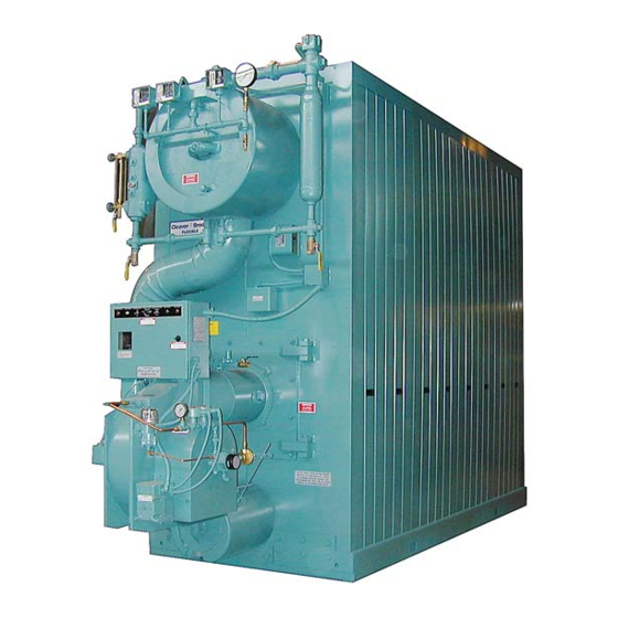
- Page 1 MODEL FLX PACKAGED BOILER 1,500,000 to 12,000,000 Btu/hr Hot Water and Steam Fuel: Light Oil, Gas or Combination Manual Part No. 750-177 R5 10/2009...
- Page 2 MODEL FLX PACKAGED BOILER Operation, Service, and Parts Manual 1,500,000 to 12,000,000 Btu/hr Fuel: Light Oil, Gas or Combination © Cleaver-Brooks 2009 Please direct purchase orders for replacement manuals to your local Cleaver-Brooks authorized representative Manual Part No. 750-177 R5 Revised 10/2009 Printed in U.S.A.
- Page 3 WARNING ! DANGER DO NOT OPERATE, SERVICE, OR REPAIR THIS EQUIPMENT UNLESS YOU FULLY UNDERSTAND ALL APPLICABLE SECTIONS OF THIS MANUAL. DO NOT ALLOW OTHERS TO OPERATE, SERVICE, OR REPAIR THIS EQUIPMENT UNLESS THEY FULLY UNDERSTAND ALL APPLICABLE SECTIONS OF THIS MANUAL. FAILURE TO FOLLOW ALL APPLICABLE WARNINGS AND INSTRUCTIONS MAY RESULT IN SEVERE PERSONAL INJURY OR DEATH.
-
Page 4: Table Of Contents
TABLE OF CONTENTS Chapter 1 Basics of Flexible Watertube Operation A. General ............... . 1-1 B. - Page 5 TABLE OF CONTENTS(continued) Chapter 5 Adjustment Procedures A. General ............... . 5-1 B.
- Page 6 TABLE OF CONTENTS(continued) Chapter 7 Inspection And Maintenance A. General ............... . 7-1 B.
-
Page 7: General
CAUTION ! DANGER The information in this manual applies directly to Cleaver- Brooks FLX Model boilers in sizes ranging from 1,500,000 The care taken in placing the boiler into initial to 12,000,000 Btu/hr input. service is vital to continuous, reliable operation. -
Page 8: The Boiler
A method of boiling out the vessel to The Model FLX boiler is a packaged watertube boiler of remove accumulations is described in Chapter 3. welded steel construction and consists of a pressure vessel,... - Page 9 GENERAL DESCRIPTION Chapter 1 Modulating Limit Pressure Control (Figure 1-2 and 1-3): Water Column Assembly (Figure 1-2): Houses the low- Senses changing boiler pressures and transmits the water cutoff and pump control and includes the water information to the modulating motor to change the gauge glass, gauge glass shutoff cocks.
-
Page 10: Hot Water Controls (All Fuels)
Chapter 1 GENERAL DESCRIPTION avoid overtightening, which can distort the seats. Use only flat-jawed wrenches on the flats provided. When installing a flange-connected valve, use a new gasket and draw the mounting bolts down evenly. Do not install or remove side outlet valves by using a pipe or wrench in the outlet. - Page 11 GENERAL DESCRIPTION Chapter 1 stop or start the burner at a preselected operating level in the boiler drops below the master low-water temperature. cutoff point. High Limit Temperature Control (Figure 1-7): Breaks a Safety Valve(s) (Figure 1-6 and 1-8): Prevent buildup circuit to stop burner operation on a rise of temperature over the design pressure of the pressure vessel.
- Page 12 Chapter 1 GENERAL DESCRIPTION remove side outlet valves by using a pipe or wrench in S UP PO RT F R O M B U I L D I N G C O NS TR U C T I O N the outlet.
-
Page 13: Profire V Burner
CHAPTER 2 Profire V Burner A. Introduction .......2-1 The burners are available in the following configurations: B. - Page 14 Chapter 2 Profire V Burner transformer is powered, and pilot valve is energized air flow with the fuel flow provides efficient combustion at all firing rates. (open). c. MAIN FUEL (green) - Illuminates when the main fuel valve or valves are energized (open). OIL SYSTEM d.
- Page 15 Profire V Burner Chapter 2 meet load demands. The low fire positions bypass oil back to A pressure actuated switch that remains closed when gas the storage tank. At high fire, the metering valve is in the pressure is above a selected setting. Should the pressure drop closed position.
- Page 16 Chapter 2 Profire V Burner Figure 2-1: Profire Burner Figure 2-2: Interior Burner Components Figure 2-2: Burner-Cutaway View 750-177...
-
Page 17: Installation
Profire V Burner Chapter 2 4X Ø3/4 K DIA. L B.C. 656-00037 STANDARD CONFIGURATION - REAR MOUNTED PANEL, GAS PILOT LINE PANEL MOUNTED BURNER MODEL 32 7/8 12 3/8 8 1/4 3 3/4 9 3/4 9 3/4 7 3/8 12 7/8 11 1/4 6 1/2 14 3/8... - Page 18 Chapter 2 Profire V Burner While these dimensions are typical for good practice, Suggested Minimum Combustion Chamber Dimensions satisfactory results may be achieved with modifications to suit some conditions. Factors such as fuel properties, total combustion volume, length of flame trave often make fixed requirements impractical.
-
Page 19: Gas Piping
Profire V Burner Chapter 2 a. Quantity of oil pumped (gph). GAS PIPING b. Length of suction line (feet). Gas service and house piping must supply the quantity of gas c. Diameter of the suction line. demanded by the unit at the pressure required at the burner d. - Page 20 Chapter 2 Profire V Burner Figure 2-11: Typical UL Gas Train, Full Modulation System, Size 1 V13 to V34 Figure 2-12: Typical UL Gas Train, Low-High-Off/Low-High-Low, Size 2 V35 to V63, Full Mod System, Size 2-3-4 V35 to V168 750-177...
- Page 21 Profire V Burner Chapter 2 Figure 2-13: Oil System Configurations 750-177...
- Page 22 Chapter 2 Profire V Burner Figure 2-14: Multiple Burners Configurations Figure 2-15: Day Tank 2-10 750-177...
- Page 23 Profire V Burner Chapter 2 Figure 2-7: Typical Flooded Loop System INSTALLATION CHECKLIST All burners are carefully assembled and tested at the factory, but before being placed in service all connectors ! DANGER CAUTION should again be checked for looseness caused during shipment.
- Page 24 Chapter 2 Profire V Burner FIRING MODES Different modulation modes are available with the Profire V burner. The Model FLX will utilize one of the following: Low - High -Low (60% damper purge). Low - High -Low (open damper purge).
-
Page 25: Combustion Air
Profire V Burner Chapter 2 LOW-HIGH-LOW MOD - LOW or 60% DAMPER PURGE Combustion Air Pressure Atomization: Two solenoid type blade damper safety shut off oil valves initiate the flow of oil controlled by a two position, Safety shut off valve(s) are from the high pressure pump to the nozzle. - Page 26 Chapter 2 Profire V Burner LOW-HIGH-LOW MOD - OPEN DAMPER PURGE Combustion Air Pressure Atomization: Two solenoid type safety blade damper shut off oil valves initiate the flow of oil from the high controlled by a two position, Safety shut off valve(s) are pressure pump to the nozzle.
- Page 27 Profire V Burner Chapter 2 FULL MODULATION - OPEN DAMPER PURGE Combustion Air Pressure Atomization: Two solenoid type safety shut A two blade damper is controlled by a off oil valves initiate the flow of oil from the high pressure pump to a return flow nozzle. In the return proportional modulating actuator (or line from the nozzle an adjustable oil metering valve motor) with mechanical linkage.
- Page 28 Chapter 2 Profire V Burner PARALLEL POSITIONING Combustion Air NOTE: Pressure Atomization: Two solenoid type safety Parallel Positioning systems incorporate independent actuators to shut off oil valves initiate the flow of oil from the high control each of the fuel and air metering pressure pump to a return flow nozzle.
-
Page 29: Startup And Operation
Profire V Burner Chapter 2 C. Startup and Operation GAS BURNERS A representative of the gas utility should turn on the gas. When the installation is complete and all electrical, fuel, Determine by a test gauge upstream of the burner regulator water, and vent stack connections are made, make certain the that sufficient pressure exists at the entrance to the gas train. - Page 30 Chapter 2 Profire V Burner Stack Thermometer and Thermocouples. OIL PRESSURE AND VACUUM If the vacuum gauge reads higher than calculated, look for restriction in the suction line, a closed valved, kinked copper WARNING tubing, plugged filter, sticking check valve, frozen oil line, ! DANGER CAUTION ! DANGER...
-
Page 31: Gas Burners
Profire V Burner Chapter 2 OIL FIRED Disconnect the electrical power to the burner. Disconnect the WARNING ! DANGER ! DANGER CAUTION electric oil safety shutoff valve. Reconnect electric power. Close the pilot line manual gas valve, if used. FAILURE TO FOLLOW THIS PROCEDURE MAY Start burner and at the time of pilot trial, with just the RESULT IN EXPLOSION, FIRE, PROPERTY DAM- electrical ignition system energized. - Page 32 Chapter 2 Profire V Burner Return the setpoint to its original position before pro- 14. When low-fire is adjusted, shut down the burner. Restart ceeding. several times to be sure the low-fire setting is suitable. Readjust if necessary. Never start the burner with fuel Shut off the combustion air blower.
-
Page 33: Normal Operation
Profire V Burner Chapter 2 perature. In automatic operation, the operating cycle always proceeds sequentially through pre-purge, pilot ignition, main flame After the boiler has reached operating temperature or ignition, run and post-purge. The length of purge and ignition pressure, turn the potentiometer switch in small incre- trial vary according to the type of programmer used. -
Page 34: Adjustments
Chapter 2 Profire V Burner D. Adjustments • improper fuel oil temperature While each burner is tested at the factory for correct operation TEST EQUIPMENT before shipment, variable conditions such as burning The following test equipment should be used to set up and characteristics of the fuel used and operating load conditions adjust the burner correctly: may require further adjustment after installation to assure... -
Page 35: Burner Settings
Profire V Burner Chapter 2 are capable of operating at low excess air and less than 50 Lockout and tag the electrical power supply to the ppm CO levels at all firing rates. burner to prevent inadvertent operation during checkout or maintenance activities. - Page 36 Chapter 2 Profire V Burner Re-connect the oil line and high voltage power cable to the assembly. Measure the position of the diffuser to the air baffle and compare to the following drawer assembly drawings. To adjust: Measure the distance between the leading edge of the diffuser and the front face of the inner ring on the air baffle assembly.
- Page 37 Profire V Burner Chapter 2 Figure 2-22: Assembly Drawing 5 Figure 2-20: Assembly Drawing 3 PILOT TURN DOWN TEST For burners equipped with a gas pilot, conduct the following test: Turn the burner switch on. This will start the blower motor and initiate the pre-purge sequence.
- Page 38 Chapter 2 Profire V Burner diaphragm and open the valve. ON-OFF BURNER ADJUSTMENTS Adjust the high-fire gas input to match maximum rating. Refer to the burner data plate located inside the control panel Adjust the gas regulator so the manifold pressure door.
-
Page 39: Burner Adjustments
Profire V Burner Chapter 2 flame is obtained and a satisfactory low-fire oil flame is L O W- H I G H - O F F & L O W- H I G H - L O W established. Turn burner off and restart to ensure smooth BURNER ADJUSTMENTS ignition is obtained at the set low-fire pressure. - Page 40 Chapter 2 Profire V Burner position. Adjust the gas regulator so the manifold pres- pressure regulating valve, remove lockscrew and adjust sure matches the rating on the burner data plate. Verify pressure by turning the allen screw clockwise to and record the readings and pressures. High-fire is typi- increase pressure, and counterclockwise to reduce pres- cally 3% to 4% O with less than 50 ppm CO.
- Page 41 Profire V Burner Chapter 2 Allow the boiler to fully warm up before making adjustments target value. for most efficient combustion. Refer to the boiler instruction 11. Modulate the burner to low-fire. Verify the readings. manual for the boiler controls settings. The burner should be adjusted to provide correct fuel flow at a constant rate, at the low-fire and high-fire position as GAS BURNERS...
- Page 42 Chapter 2 Profire V Burner COMBUSTION AND HIGH CO EMISSIONS WILL is at the OPEN position). RESULT. Monitor O and CO levels during this process. Adjust the high-fire fuel input to match maximum oil The introduction of FGR into the combustion chamber pressure.
-
Page 43: Maintenance
Profire V Burner Chapter 2 ! DANGER CAUTION ANY COVER PLATES, ENCLOSURES, OR GUARDS ANCHORED TO THE BURNER, OR ANY BURNER RELATED EQUIPMENT, MUST REMAIN IN POSITION AT ALL TIMES. ONLY DURING MAINTENANCE AND SERVICE SHUTDOWN CAN THESE COVER PLATES, ENCLOSURES, OR GUARDS BE ALLOWED TO BE REMOVED. -
Page 44: Gas System
Chapter 2 Profire V Burner Maintenance checks on the flexible coupling between the fuel MOTORS unit and motor for alignment, tightness and wear and oil Supply voltage to the motor must not vary more than 10% piping connection tightness should also be made at regular from data plate ratings. -
Page 45: Extended Shutdown
Profire V Burner Chapter 2 The pilot should be checked monthly for loosening of components and carbon buildup. Before removing the pilot, ensure that the fuel supply is shut off. On direct spark oil units, once you have removed the drawer assembly, check the electrode to nozzle gap and adjust if necessary. - Page 46 Chapter 2 Profire V Burner RECOMMENDED MAINTENANCE SCHEDULE ITEM SERVICE BY REMARKS DAILY Gauges, Monitors, and Indicators Operator Make visual inspection and record readings in log. Instrument and Equipment Settings Operator Make visual check against recommended specifications. Low Water, Fuel Cutoff, and Alarms Operator Refer to instructions.
-
Page 47: Troubleshooting
Profire V Burner Chapter 2 F. Troubleshooting PROBLEM SOLUTION Burner Does Not Start No voltage at program relay pwoer input terminals. a. Main disconnect switch open. b. Blown control circuit fuse. c. Loose or broken electrical connection. Program relay safety switch requires resetting. Limit circuit not completed - no voltage at end of limit circuit program relay termi- nal. - Page 48 Chapter 2 Profire V Burner PROBLEM SOLUTION No Ignition Lack of spark. a. Electrode grounded or porcelain cracked. b. Improper electrode setting. c. Loose terminal on ignition cable, cable shorted. d. Inoperative ignition transformer. e. Insufficient or no voltage at pilot ignition circuit terminal. Spark but no flame.
- Page 49 Profire V Burner Chapter 2 PROBLEM SOLUTION Burner Stays in Low-Fire Pressure or temperature above modulating control setting. Manual-automatic switch in wrong position. Inoperative modulating motor. Defective modulating control. Binding or loose linkages, cams, setscrews, etc. PROBLEM SOLUTION Shutdown Occurs During Firing Loss or stoppage of fuel supply.
- Page 50 Chapter 2 Profire V Burner PROBLEM SOLUTION Modulating Motor Does Not Manual-automatic switch in wrong position. Operate Linkage loose or jammed. Motor does not drive to open or close during pre-purge or close on burner shut- down. a. Motor defective. b.
-
Page 51: Burner Specs
Profire V Burner Chapter 2 G. Burner Specs Model FLX Burner Characteristics Burner Maximum Fan Motor (3450 RPM) Model No. Burner Model Input MBH Voltage FLX-150 1500 PFVLG-15 115/230/1/60 FLX-200 2000 PFVLG-20 115/230/1/60 FLX-250 2500 PFVLG-25 115/230/1/60 FLX-300 3000 PFVLG-30... - Page 52 Chapter 2 Profire V Burner Model FLX Minimum Required Gas Pressure Std. Gas Train Size Min. Gas Pressure Min. Gas Pressure Model No. Burner Model (In.) Note 3 (in WC) Note 4 (in WC) Note 5 FLX-150 11.2 12.5 PFVG-15 FLX-200 19.4...
- Page 53 Profire V Burner Chapter 2 START-UP / SERVICE REPORT The following information should be filled in by the service technician at start-up or after any adjustment to the burner. A copy of the start-up report MUST be returned to CB in order to validate the warranty of the burner. Burner Model Serial Number Start-up Date...
- Page 54 Chapter 2 Profire V Burner 2-42 750-177...
-
Page 55: Pressure Vessel Care
CHAPTER 3 Pressure Vessel Care A. General........3-1 B. -
Page 56: System Pressure
DT = 20°F DT = 40°F DT = 60°F DT = 80°F DT = 100°F MODEL DP (PSIG) DP (PSIG) DP (PSIG) DP (PSIG) (PSIG) FLX-150 1.14 122.0 0.30 61.1 0.13 41.1 0.08 30.8 0.05 24.4 FLX-200 1.14 162.3 0.30 81.1... -
Page 57: Water Requirements (Steam Boilers)
Note: In order to maintain a minimum outlet water temperature of 150°F the low limit of The internal dynamics of the Model FLX steam boilers the Operating Temperature Control should require the capability to deliver large quantities of feed water be set at least 10°... -
Page 58: Water Treatment
Chapter 3 Pressure Vessel Care BOILER MODEL 1000 1100 1200 Minimum Feed Rate (gpm) 11.6 13.2 14.9 16.5 18.2 19.8 23.1 26.4 29.7 33.0 36.3 39.6 Note: Feedwater to the boiler must be at least 60 °F for minimum performance; 212 °F is preferred. Table 3-2: Minimum Boiler Feed Water Flow Rates (Steam Boiler) Because of the variables involved, no one boiler compound can be considered a cure-all;... - Page 59 Pressure Vessel Care Chapter 3 control system, in order to lower the concentration of solids CAUTION in the water. ! DANGER Solids are introduced to the boiler with the feedwater, even When initially opening the blowdown valve, though this water may be treated prior to use. These solids open the valve slowly to heat the discharge become less soluble when the water is heated and evaporated, piping.
-
Page 60: Cleaning
The water capacity of Cleaver- Cleaning of the waterside of the pressure vessel should be Brooks FLX Boilers is listed in Table 3-4. done during the course of initial installation. The waterside of the pressure vessel must be cleansed of grease, sludge, and foreign material. - Page 61 Pressure Vessel Care Chapter 3 handhole cover. (Use standard service gaskets during the amount being equally divided among the various manual boilout procedure.) blowdown points and continuous blowdown system. Blow the surface and/or continuous blow-down points The relief valve(s) must be removed before adding the first, followed by the other blowdown points lower on boilout solution so that neither the solution nor the the boiler.
-
Page 62: Washing Out
Chapter 3 Pressure Vessel Care H. WASHING OUT available. Be prepared to perform any testing required by the inspector, including a hydrostatic test. Depending on system integrity, feedwater quality, or When shutting down a boiler, the load should be reduced operating conditions, the water side of the boiler may need to gradually and the pressure vessel should be cooled at a rate be washed out on occasion. -
Page 63: Preparation For Extended Lay-Up
Pressure Vessel Care Chapter 3 Waterside Inspection Preparing The Boiler For Layup Check all water piping and valves for leaks, wear, corrosion, To prepare a boiler for layup, thoroughly clean the fireside by and other damage. Replace or repair the piping and valves as removing any soot or other products of combustion from the necessary. - Page 64 Chapter 3 Pressure Vessel Care possibility of freezing temperatures must be considered. WARNING Again, take care to protect metal surfaces. Because of the ! DANGER number of variables, it is difficult to offer definite recommendations. However, it is suggested that the pressure Materials described in this section may be vessel be drained, thoroughly cleaned internally, and refilled considered hazardous under the U.S.
-
Page 65: Sequence Of Operation
CHAPTER 4 Sequence Of Operation A. General ........4-1 B. -
Page 66: Sequence Of Operation - Oil Or Gas
Chapter 4 Sequence Of Operation C. SEQUENCE OF OPERATION - OIL Blower Motor Starter Circuit OR GAS • Blower motor starter (BMS) On a combination fuel unit, the gas/oil switch must be set for Running lnterlock Circuit the proper fuel. •... -
Page 67: Flame Loss Sequence
Sequence Of Operation Chapter 4 The pilot flame must be established and proven by the flame the pressure vessel metal and refractory to detector (FD) within a 10 second period in order for the undesirable conditions. ignition cycle to continue. If for any reason this does not The burner starting cycle is now complete. - Page 68 Chapter 4 Sequence Of Operation The blower motor will continue to operate. The flame failure Preventive maintenance and scheduled inspection of all light and the alarm bell (optional) are energized 10 seconds components should be followed. Periodic checking of the later.
- Page 69 Sequence Of Operation Chapter 4 MNEMONIC DESCRIPTION MNEMONIC DESCRIPTION Burner Switch Amber (Color Of Pilot Light) Boiler Selector Switch AAFL Atomizing Air Failure Light BWPM Booster Water Pump Motor AAFR Atomizing Air Failure Relay Booster Water Thermostat AAPL Atomizing Air Proven Light AAPS Atomizing Air Proving Switch CAFL...
- Page 70 Chapter 4 Sequence Of Operation MNEMONIC DESCRIPTION MNEMONIC DESCRIPTION FDJB Flame Detector Junction Box H/LWA High Low Water Alarm FDPS Flow Differential Pressure Switch High Limit Control Flame Failure Alarm HLFC High-Low Fire Control Flame Failure Light HLPC High Limit Pressure Control Flame Failure Relay HLTC High Limit Temperature Control...
- Page 71 Sequence Of Operation Chapter 4 MNEMONIC DESCRIPTION MNEMONIC DESCRIPTION LLPR Low Limit Pressure Relay No Flow Relay Lead Lag Relay NGHPV Natural Gas Housing Purge Valve LLTC Low Limit Temperature Control LLTR Low Limit Temperature Relay Outlet Damper Actuator LOPL Low Oil Pressure Light Outlet Damper Motor LOPR...
- Page 72 Chapter 4 Sequence Of Operation MNEMONIC DESCRIPTION MNEMONIC DESCRIPTION Power On Light STLWR Surge Tank Low Water Relay Pilot Oil Valve Pre-Purging Light (T.C.) Timed Closed Post Purge Relay (T.O.) Timed Open PPTD Post Purge Time Delay Terminal Block Program Relay Thermocouple Purge Ready Light Time Clock...
-
Page 73: A. General
CHAPTER 5 Adjustment Procedures A. General........5-1 L. -
Page 74: Adjustment Procedures
Chapter 5 Adjustment Procedures E. BURNER OPERATING CONTROLS Initial adjustment should be made with the motor in full closed position, that is with the shaft on the power end of - GENERAL the motor in its most counterclockwise position. Note: Adjustments to the boiler operating The closer the linkage rod connector is to the drive shaft, controls should be made by an authorized the less the arm will travel;... - Page 75 Adjustment Procedures Chapter 5 Separate and independent controls affect modulated firing and burner on-off cycling. Figure 5-3 depicts a typical setting relationship of the operating limit control, modulating control and the high limit control. The burner will be “on” whenever the pressure or temperature is less than point B and “off”...
- Page 76 Chapter 5 Adjustment Procedures 100% Modulation Control Response Firing Rate Operating Limit Control Response High Limit Control Safety Shutdown Minimum Input (Low Fire) Falling Temp. or Pressure Modulated Firing “ON - OFF” Range Differential Rising Temp. or Pressure Burner Off (Burner OFF) (Burner OFF) (Burner ON)
-
Page 77: Modulating Pressure Control (Steam)
Adjustment Procedures Chapter 5 on a pressure increase. To reset, allow pressure to return to settings and should not exceed 90% of the valve setting. The normal and then press the reset button. control requires manual resetting after it shuts off the burner. In the setting of the controls, consideration must be given to I. -
Page 78: Low Water Cutoff Devices
Chapter 5 Adjustment Procedures N. GAS PILOT FLAME ADJUSTMENT The size of the gas pilot flame is regulated by adjusting the gas flow through the pilot gas regulator. The flame must be sufficient to ignite the main flame and to be seen by the flame detector. -
Page 79: Gas Fuel Combustion Adjustment
Adjustment Procedures Chapter 5 Pressure Correction Note: The information given in this section is for all practical purposes sufficient to set The flow rate outlined in Section P is based on a “base” and adjust controls for gas input. Your gas pressure, which is usually atmospheric or 14.7 psia. -
Page 80: Low Gas Pressure Switch
Chapter 5 Adjustment Procedures maximum CO level standardly allowed is less than 400 ppm. If the air damper needs to be adjusted in order to provide the However, this may change subject to local regulations. correct low fire air/fuel ratio, combustion must be rechecked at higher firing rates and adjusted as required. -
Page 81: Fuel Oil Combustion Adjustment
STD GAS PRESSURE PRESSURE BURNER MODEL NO. TRAIN SIZE REGULATOR INLET (IN.W.C.) (IN.W.C.) MODEL (IN.) Note 3 PRESSURE FACTOR Note 4 Note 5 PRESSURE (PSIG) FLX-150 11.2 12.5 PFVG-15 1.05 FLX-200 19.4 21.7 PFVG-20 1.11 FLX-250 12.4 15.7 PFVG-25 FLX-300 15.9... -
Page 82: Low Oil Pressure Switch
Chapter 5 Adjustment Procedures FIRST VISIBLE TRACE OF STACK HAZE PER CENT O IN FLUE GAS PER CENT CO 1/10 of 1% CO = 1,000 PPM PER CENT EXCESS AIR Figure 5-5: Flue Gas Analysis Chart for Natural Gas Final adjustment to fuel input must be made to produce a minimum of smoke. -
Page 83: Troubleshooting
CHAPTER 6 Troubleshooting possibly eliminate overlooking an obvious condition, often WARNING one that is relatively simple to correct. ! DANGER If an obvious condition is not apparent, check the continuity Troubleshooting should be performed only of the circuits with a voltmeter or test lamp. Each circuit can by personnel who are familiar with the be checked and the fault isolated and corrected. - Page 84 Chapter 6 Troubleshooting Problem Solution BURNER DOES NOT START No voltage at program relay power input terminals. A. Main disconnect switch open. B. Blown control circuit fuse. C. Loose or broken electrical connection. Program relay safety switch requires resetting. Limit circuit not completed—no voltage at end of limit circuit program relay terminal.
- Page 85 Troubleshooting Chapter 6 Problem Solution PILOT FLAME, BUT NO Insufficient pilot flame. MAIN FLAME Gas Fired Unit. A. Manual gas cock closed. B. Main gas valve inoperative. C. Gas pressure regulator inoperative. Oil fired unit. A. Oil supply cut off by obstruction, closed valve, or loss of suction. B.
- Page 86 Chapter 6 Troubleshooting Problem Solution SHUTDOWN OCCURS Improper air/fuel ratio (lean fire). DURING FIRING A. Slipping linkage. B. Damper stuck open. C. Fluctuating fuel supply. 1). Temporary obstruction in fuel line. 2). Temporary drop in gas pressure. Interlock device inoperative or defective. MODULATING MOTOR Manual-automatic switch in wrong position.
- Page 87 Troubleshooting Chapter 6 Problem Solution 2. Cold system startup. A. Any time a boiler is started with a cold system, it will produce condensate until internal surface temperatures exceed 130 F. Internal condensation will not be produced ° once a boiler has warmed up. Condensate will dry up after a short time. Limit number of cold starts.
- Page 88 Chapter 6 Troubleshooting 750-177...
-
Page 89: General
CHAPTER 7 Inspection and Maintenance A. General ........7-1 B. -
Page 90: Fireside Cleaning
Chapter 7 Inspection and Maintenance operator with an excellent opportunity to perform a detailed Tubes should be brushed with a wire brush to remove any check of all components of the boiler, including piping, soot or other accumulations. Refractory surfaces should be valves, pumps, gaskets, refractory, etc. - Page 91 Inspection and Maintenance Chapter 7 The flue outlet and stack should also be inspected annually Install gasket on side casing panels so it extends past the top and cleaned as necessary. Commercial firms are available to and bottom by 1/4" or more and 1/16" to 1/8" out the back at perform this work.
-
Page 92: Controls
Chapter 7 Inspection and Maintenance E. CONTROLS accordance with Section IV of the ASME Boiler and Pressure Vessel Code. Relief Valves Low Water Controls (Hot Water) The relief valve is a very important safety device and Most instances of major boiler damage result from operating deserves attention accordingly. - Page 93 Inspection and Maintenance Chapter 7 when the blow down valve is open allowing water to drain CAUTION from the control. The test-n-check valves permit testing of the ! DANGER control without draining the entire system therefore allowing regularly scheduled verification of float style low water If a control does not break the circuit to stop cutoff.
-
Page 94: Oil Burner Maintenance
Chapter 7 Inspection and Maintenance Electrical Controls Refer to the burner manual for information regarding tests of the flame safeguard system. Contact your local Cleaver- The operating controls should be inspected monthly. Brooks authorized representative for assistance, if required. Examine the tightness of electrical connections and keep the controls clean. -
Page 95: Gas Burner Maintenance
Inspection and Maintenance Chapter 7 G. GAS BURNER MAINTENANCE the condition of the refractory and insulation and will guard against unexpected downtime for repairs. Refer to the burner sections for specific information regarding operation and maintenance of the burner. The I. - Page 96 Chapter 7 Inspection and Maintenance Sight Port gasket. Start tightening at the top and proceed around the door, alternately tightening opposite fasteners until all are Inspect the area around the sight port for paint discoloration. snug. After the boiler is back in operation, check for gas leaks A hot spot around the rear sight port is caused by either a poor around the door opening, and retighten the fasteners as seal between the sight port insulator and the wall, a cracked...
- Page 97 CHAPTER 8 PARTS Flextube Casing, Hot Water ........... 8-2,3 Flextube Casing, Low Pressure Steam .
- Page 98 Figure: 8-1 Typical Hot Water Flextube Casing...
- Page 99 Part List, Hot Water 1100 ITEM DESCRIPTION PART # PART # PART # PART # PART # Base 315-1124 315-1169 315-1180 315-1194 315-1203 Roof 315-1127 315-1167 315-1178 315-1192 315-1202 Front wall, w/o Hinge 315-1262 315-1265 Front wall w Hinge 315-1128 315-1166 315-1177 315-1191...
- Page 100 Figure: 8-2 Typical Low Pressure Steam Flextube Casing...
- Page 101 Part List, LP Steam 1100 ITEM DESCRIPTION PART # PART # PART # PART NO. PART # Base 315-1124 315-1169 315-1180 315-1194 315-1203 Roof 315-1215 315-1230 315-1239 315-1250 315-1260 Front wall, w/o Hinge 315-1263 315-1264 Front wall w Hinge 315-1216 315-1229 315-1138 315-1249...
- Page 102 Figure: 8-3 Typical High Pressure Steam Flextube Casing...
- Page 103 Parts List, HP Steam 1100 ITEM DESCRIPTION PART # PART # PART # PART # PART # Base 315-1124 315-1169 315-1180 315-1194 315-1203 Roof 315-1215 315-1230 315-1239 315-1250 315-1260 Front wall w/o Hinge 315-1263 315-1264 Front wall w Hinge 315-1216 315-1229 315-1238 315-1249...
-
Page 104: Steam Pressure Controls
Parts Chapter 8 Steam Pressure Controls 750-177... -
Page 105: Water Level Controls
Chapter 8 Parts Water Level Controls 750-177... - Page 106 Parts Chapter 8 Water Level Controls continued 8-10 750-177...
-
Page 107: Water Column, Main And Aux. - 15# Steam
Chapter 8 Parts Water Column, Main and Aux. - 15# Steam 750-177 8-11... -
Page 108: Water Column, Main And Aux. - 150# Steam
Parts Chapter 8 Water Column, Main and Aux. - 150# Steam 8-12 750-177... - Page 110 Web Address: http://www.cleaverbrooks.com...
Need help?
Do you have a question about the FLX and is the answer not in the manual?
Questions and answers